2007 SUZUKI GRAND VITARA ignition
[x] Cancel search: ignitionPage 69 of 211

Downloaded from www.Manualslib.com manuals search engine 4-7 INSTRUMENT PANEL
66J21-03E
systems (other than ABS) will turn on
automatically and the light will go out.
For details of the ESP
® systems, refer to
“Electronic Stability Program (ESP
®)” in
the “OPERATING YOUR VEHICLE” sec-
tion.
Oil Pressure Light
50G051
This light comes on when the ignition
switch is turned to the “ON” position, and
goes out when the engine is started. The
light will come on and remain on if there is
insufficient oil pressure. If the light comes
on when driving, pull off the road as soon
as you can and stop the engine. Check the
oil level and add oil if necessary. If there is
enough oil, the lubrication system should
be inspected by your SUZUKI dealer
before you drive the vehicle again.
Charging Light
50G052
This light comes on when the ignition
switch is turned to the “ON” position, and
goes out when the engine is started. The
light will come on and remain on if there is
something wrong with the battery charging
system. If the light comes on when the
engine is running, the charging system
should be inspected immediately by your
SUZUKI dealer.
Driver’s Seat Belt Reminder Light
60G049
If the driver’s seat belt is unbuckled when
the ignition switch is turned to the “ON”
position, this light will come on and then
blink. When the light comes on, a buzzer
will also sound intermittently for about 6
seconds. The reminder will repeat several
times under certain conditions until the
driver’s seat belt is buckled. After repeat-
ing several times, the reminder will be can-
celed even if the driver’s seat belt remains
unbuckled.
For details about the seat belt reminder,
refer to “Seat Belts and Child Restraint
Systems” in the “BEFORE DRIVING” sec-
tion.
CAUTION
If you operate the engine with this
light on, severe engine damage can
result.
Do not rely on the Oil Pressure
Light to indicate the need to add
oil. Be sure to periodically check
the engine oil level.
WARNING
It is absolutely essential that the
driver and passengers wear their
seat belts at all times. Persons who
are not wearing seat belts have a
much greater risk of injury if an acci-
dent occurs. Make a regular habit of
buckling your seat belt before putting
the key in the ignition.
Warning and Indicator Lights: 8
Page 70 of 211

Downloaded from www.Manualslib.com manuals search engine 4-8 INSTRUMENT PANEL
66J21-03E
“AIR BAG” Light
63J030
This light monitors inflators, crash sensors,
seat belt pretensioners, the front passen-
ger sensing system, and corresponding
electrical circuits.
This light blinks for several seconds when
the ignition switch is turned to the “ON”
position so you can check if the light is
working. The light will come on and stay on
if there is a problem in the air bag system
or the seat belt pretensioner system.
Malfunction Indicator Light
65D530
Your vehicle has a computer-controlled
emission control system. A malfunction
indicator light is provided on the instrument
panel to indicate when it is necessary to
have the emission control system serviced.
The malfunction indicator light comes on
when the ignition switch is turned to the
“ON” position to let you know the light is
working and goes out when the engine is
started.
If the malfunction indicator light comes on
or blinks when the engine is running, ser-
vice to the emission control system is nec-
essary. Bring the vehicle to your SUZUKI
dealer to have the emission control system
serviced right away and avoid hard accel-
eration until the service is performed.NOTE:
If the fuel filler cap is not installed fully, the
electrical system gets wet (such as by driv-
ing through a deep puddle of water) or the
fuel tank gets nearly empty, the malfunc-
tion indicator lamp may come on. If so, the
lamp will go off after driving a few times
after the fuel filler cap is installed fully, the
electrical system dries out or the fuel tank
is filled.
WARNING
If the “AIR BAG” light does not blink
when the ignition switch is turned to
the “ON” position or stays on or
comes on when driving, the air bag
system or the seat belt pretensioner
system (if equipped) may not work
properly. Have both systems
inspected by an authorized SUZUKI
dealer.
CAUTION
Continuing to drive the vehicle when
the malfunction indicator light is on
or blinking can cause permanent
damage to the vehicle’s emission
control system, and can affect fuel
economy and driveability.
Warning and Indicator Lights: 8
Page 71 of 211

Downloaded from www.Manualslib.com manuals search engine 4-9 INSTRUMENT PANEL
66J21-03E
Low Fuel Warning Light
54G343
If this light comes on, fill the fuel tank
immediately.
NOTE:
The activation point of this light varies
depending on road conditions (for exam-
ple, slope or curve) and driving conditions
because of fuel moving in the tank.Open Door Warning Light
54G391
This light remains on until all doors are
completely closed.
“CRUISE” Indicator Light
(if equipped)
52D113
When the cruise control system is on, this
light will be on.“SET” Indicator Light (if equipped)
65D474
When the vehicle’s speed is controlled by
the cruise control system, this light will be
on.
Keyless Start System Indicator
Light (if equipped)
62J041
When you push the ignition switch for vehi-
cle with the keyless start system, this light
will come on in blue or red. If this light
comes on in blue, you can turn the ignition
switch without using an ignition key. If this
light comes on in red, you can not turn the
ignition switch without using an ignition
key. For details, refer to “Ignition Switch” in
the “STEERING COLUMN CONTROLS”
section.
If this light blinks in red, it reminds you that
the remote controller is not in the vehicle.
For details, refer to “Keyless Start System”
in the “BEFORE DRIVING” section.
Warning and Indicator Lights: 8
Page 73 of 211

Downloaded from www.Manualslib.com manuals search engine 4-11 INSTRUMENT PANEL
66J21-03E
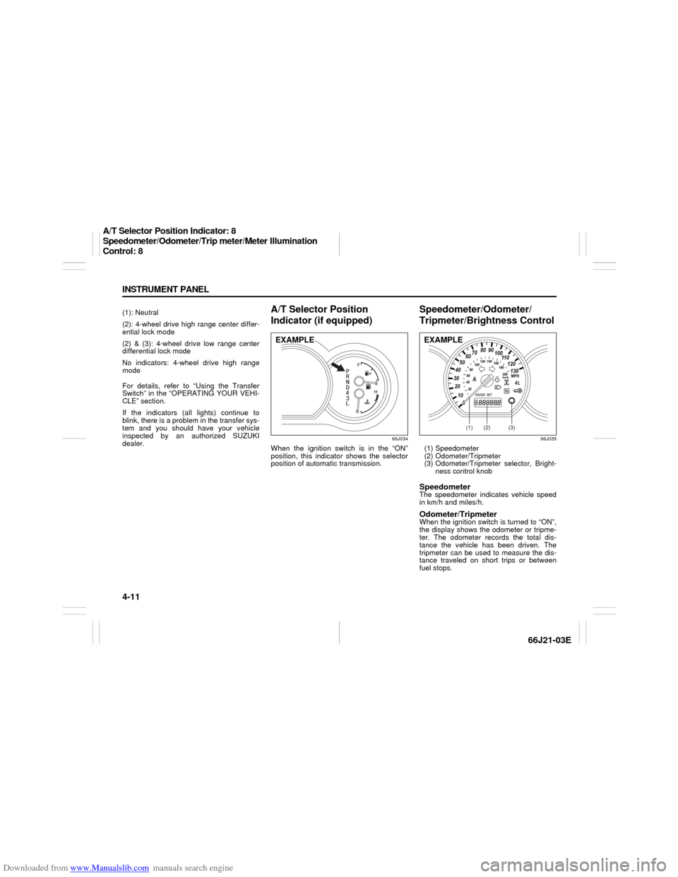
(1): Neutral
(2): 4-wheel drive high range center differ-
ential lock mode
(2) & (3): 4-wheel drive low range center
differential lock mode
No indicators: 4-wheel drive high range
mode
For details, refer to “Using the Transfer
Switch” in the “OPERATING YOUR VEHI-
CLE” section.
If the indicators (all lights) continue to
blink, there is a problem in the transfer sys-
tem and you should have your vehicle
inspected by an authorized SUZUKI
dealer.
A/T Selector Position
Indicator (if equipped)
66J034
When the ignition switch is in the “ON”
position, this indicator shows the selector
position of automatic transmission.
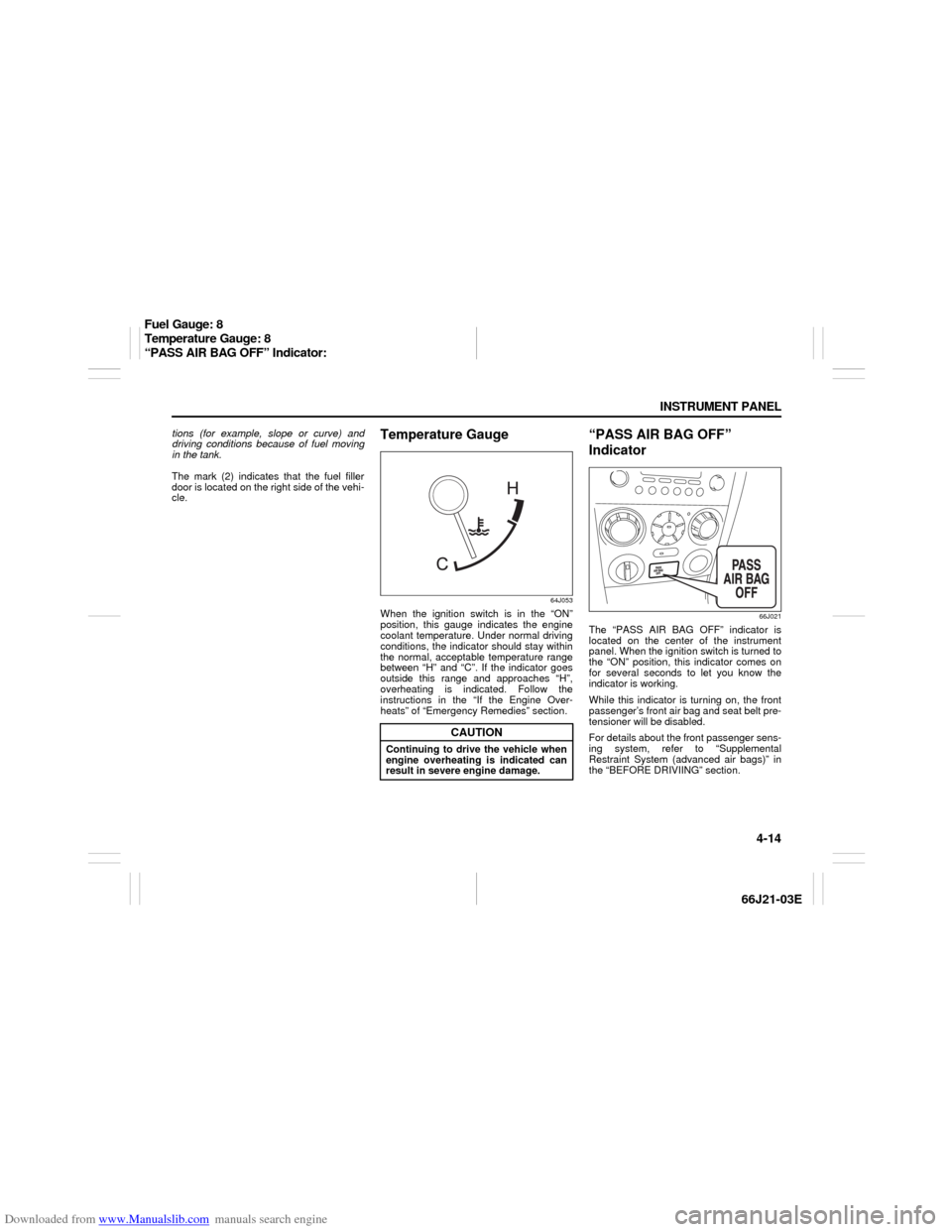
Speedometer/Odometer/
Tripmeter/Brightness Control
66J035
(1) Speedometer
(2) Odometer/Tripmeter
(3) Odometer/Tripmeter selector, Bright-
ness control knobSpeedometerThe speedometer indicates vehicle speed
in km/h and miles/h.Odometer/TripmeterWhen the ignition switch is turned to “ON”,
the display shows the odometer or tripme-
ter. The odometer records the total dis-
tance the vehicle has been driven. The
tripmeter can be used to measure the dis-
tance traveled on short trips or between
fuel stops.
EXAMPLE
(1)
(2)
(3)
EXAMPLE
A/T Selector Position Indicator: 8
Speedometer/Odometer/Trip meter/Meter Illumination
Control: 8
Page 74 of 211

Downloaded from www.Manualslib.com manuals search engine 4-12 INSTRUMENT PANEL
66J21-03E
64J049
When the ignition switch is turned to the
“ON” position, the display shows the
odometer or trip meter.
The display shows three types of indica-
tion; odometer, trip meter A and trip meter
B. Push the selector knob (3) quickly to
switch the indication among the three.
You can use the two trip meters (A and B)
independently.
64J205
Hold in the selector knob for about 2 sec-
onds to reset the trip meter to zero.
Brightness Control
66J213
(3) Brightness control knob
(4) In this position, the meter lights are
the dimmest and the other instrument
panel lights are turned off.
(5) In this position, the instrument panel
lights are the brightest.
Your vehicle has a system to automatically
dim the instrument panel lights when the
ignition switch is in the “ON” position and
the lighting switch is either (a) turned to the
second or third position, or (b) turned to
the “AUTO” position and it is dark around
the light sensor. The level of brightness
depends on the position of the brightness
control knob (3).
To reduce the brightness and activate the
automatic dimming feature, turn the knob
(3) counterclockwise. When the knob (3) is
turned counterclockwise to position (4), the
CAUTION
Keep track of your odometer reading
and check the maintenance sched-
ule regularly for required services.
Increased wear or damage to certain
parts can result from failure to per-
form required services at the proper
mileage intervals.
(3) (A) (B)
(C)
About 2 seconds
(3)
(3)
(5) (4)
EXAMPLE
Speedometer/Odometer/Trip meter/Meter Illumination
Control: 8
Page 76 of 211

Downloaded from www.Manualslib.com manuals search engine 4-14 INSTRUMENT PANEL
66J21-03E
tions (for example, slope or curve) and
driving conditions because of fuel moving
in the tank.
The mark (2) indicates that the fuel filler
door is located on the right side of the vehi-
cle.
Temperature Gauge
64J053
When the ignition switch is in the “ON”
position, this gauge indicates the engine
coolant temperature. Under normal driving
conditions, the indicator should stay within
the normal, acceptable temperature range
between “H” and “C”. If the indicator goes
outside this range and approaches “H”,
overheating is indicated. Follow the
instructions in the “If the Engine Over-
heats” of “Emergency Remedies” section.
“PASS AIR BAG OFF”
Indicator
66J021
The “PASS AIR BAG OFF” indicator is
located on the center of the instrument
panel. When the ignition switch is turned to
the “ON” position, this indicator comes on
for several seconds to let you know the
indicator is working.
While this indicator is turning on, the front
passenger’s front air bag and seat belt pre-
tensioner will be disabled.
For details about the front passenger sens-
ing system, refer to “Supplemental
Restraint System (advanced air bags)” in
the “BEFORE DRIVIING” section.
CAUTION
Continuing to drive the vehicle when
engine overheating is indicated can
result in severe engine damage.
Fuel Gauge: 8
Temperature Gauge: 8
“PASS AIR BAG OFF” Indicator:
Page 79 of 211

Downloaded from www.Manualslib.com manuals search engine 4-17 INSTRUMENT PANEL
66J21-03E
Transfer Switch (if equipped)
66J168
The transfer switch is located on the center
of the instrument panel.
For details on how to use this switch, refer
to “Using the Transfer Switch” in the
“OPERATING YOUR VEHICLE” section.
Glove Box
64J065
To open the glove box, pull the latch lever.
To close it, push the lid until it latches
securely. If a lock is equipped on the latch
lever, lock the glove box by inserting the
key and turning it clockwise and unlock the
glove box by turning the key counterclock-
wise.
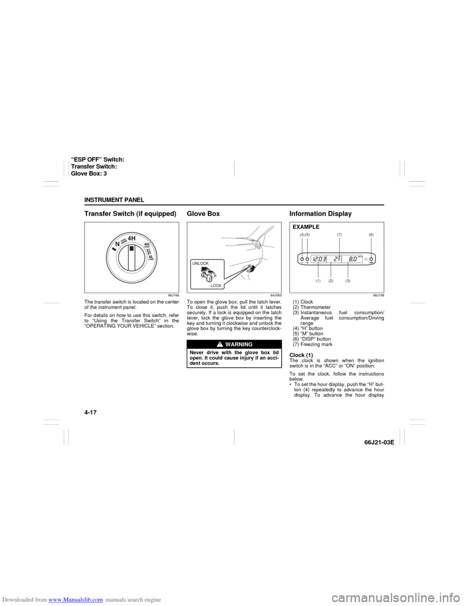
Information Display
66J198
(1) Clock
(2) Thermometer
(3) Instantaneous fuel consumption/
Average fuel consumption/Driving
range
(4) “H” button
(5) “M” button
(6) “DISP” button
(7) Freezing markClock (1)The clock is shown when the ignition
switch is in the “ACC” or “ON” position.
To set the clock, follow the instructions
below.
To set the hour display, push the “H” but-
ton (4) repeatedly to advance the hour
display. To advance the hour display
WARNING
Never drive with the glove box lid
open. It could cause injury if an acci-
dent occurs.UNLOCK
LOCK
(4)
(2)
(1)
(3)
(5)
(6)
(7)
EXAMPLE
“ESP OFF” Switch:
Transfer Switch:
Glove Box: 3
Page 80 of 211

Downloaded from www.Manualslib.com manuals search engine 4-18 INSTRUMENT PANEL
66J21-03E
quickly, hold in the “H” button (4) for
about 1 second and continue holding.
To set the minute display, push the “M”
button (5) repeatedly to advance the
minute display. To advance the minute
display quickly, hold in the “M” button (5)
for about 1 second and continue holding.Thermometer (2)The thermometer shows the outside tem-
perature when the ignition switch is in the
“ON” position.
If the outside temperature nears freezing,
the mark (7) will come on when the display
shows the outside temperature.
NOTE:
The thermometer will not indicate the
actual outside temperature when driving at
low speed, or when stopped.
You can change the unit indication of the
thermometer between °F and °C.
To change the indication, follow the
instructions below.
1) Turn the ignition switch to the “ACC” or
“ON” position while holding in the
“DISP” button (6).
The unit display of the thermometer will
blink.
66J199
2) Push the “DISP” button (6) quickly to
change the indication between °F and
°C as shown in the illustration.
3) Hold in the “DISP” button (6) for more
than 2 seconds, and the unit indication
will stop blinking.
If you don’t push the “DISP” button (6)
within about 8 seconds after the unit
display starts blinking, the unit display
will automatically stop blinking.Fuel Consumption and Driving
Range (3)This display can be changed to show
instantaneous fuel consumption, average
fuel consumption, driving range. Also, the
display of fuel consumption can be turned
off if you desire.
66J200
Every time you push the “DISP” button (6),
the display will be changed among the fol-
lowing four displays.
(a) Instantaneous fuel consumption
(b) Average fuel consumption
(c) Driving range
(d) No display
(a)
(b)
(c)(d)
Information Display: