2007 SUZUKI GRAND VITARA air condition
[x] Cancel search: air conditionPage 66 of 211

Downloaded from www.Manualslib.com manuals search engine 4-4 INSTRUMENT PANEL
66J21-03E
inflation pressure as specified in the vehi-
cle placard and owner’s manual.
The low tire pressure warning light is also
used to inform you of a TPMS malfunction.
When the system detects a malfunction,
this light will flash for approximately one
minute and then remain continuously illu-
minated. This sequence will be repeated
approximately ten minutes after subse-
quent vehicle start-ups as long as the mal-
function exists.
NOTE:
The low tire pressure warning light may not
come on immediately if you have a sudden
loss of air pressure.
Refer to “Tire Pressure Monitoring System”
in the “OPERATING YOUR VEHICLE”
section for additional details on the tire
pressure monitoring system. Refer to
“Tires” in the “INSPECTION AND MAIN-
TENANCE” section for information on
maintaining proper tire pressure.
WARNING
If the low tire pressure warning light
does not come on when the ignition
is turned to the “ON” position, or
comes on and blinks while driving
there may be a problem with the tire
pressure monitoring system. Have
your vehicle inspected by an autho-
rized SUZUKI dealer. Even if the light
turns off after blinking, indicating
that the monitoring system has
recovered, make sure to have an
authorized SUZUKI dealer check the
system.
WARNING
The load rating of your tires is
reduced at lower inflation pressures.
If your tires become even moderately
under-inflated, the vehicle load may
exceed the load rating of the tires,
which can lead to tire failure. The low
tire pressure warning light will not
alert you of this condition. The warn-
ing light will only come on when one
or more of your tires become signifi-
cantly under-inflated. Check and
adjust your tire inflation pressure at
least once a month. Refer to “Tires”
in the “INSPECTION AND MAINTE-
NANCE” section.
WARNING
If the low tire pressure warning light
comes on and stays on, reduce your
speed and avoid abrupt steering and
braking. Stop in a safe place as soon
as possible and check your tires.
If you have a flat tire, replace it with
the spare tire. Refer to “Jacking
Instructions” in the “EMERGENCY
SERVICE” section. Refer to
“Replacing Tires and/or Wheels”
for instructions on how to restore
normal operation of the tire pres-
sure monitoring system after you
have had a flat tire.
(Continued)
WARNING
(Continued)
If one or more of your tires is
under-inflated, adjust the inflation
pressure in all of your tires to the
recommended inflation pressure as
soon as possible.
Be aware that driving on a signifi-
cantly under-inflated tire can cause
the tire to overheat and can lead to
tire failure, and may affect steering
control and brake effectiveness. This
could lead to an accident, resulting in
severe injury or death.
Warning and Indicator Lights: 8
Page 67 of 211

Downloaded from www.Manualslib.com manuals search engine 4-5 INSTRUMENT PANEL
66J21-03E
Brake System Warning Light
65D477
This light comes on briefly when the igni-
tion switch is turned to the “ON” position.
The light also comes on under the follow-
ing conditions: 1) when the parking brake
is engaged, and 2) when the fluid in the
brake fluid reservoir falls below the speci-
fied level. The light should go out after fully
releasing the parking brake, if the fluid
level in the brake fluid reservoir is ade-
quate.
If the brake system warning light comes on
while you are driving the vehicle, it may
mean that there is something wrong with
the vehicle’s brake system. If this happens,
you should:
1) Pull off the road and stop carefully.2) Test the brakes by carefully starting
and stopping on the shoulder of the
road.
3) If you determine that it is safe, drive
cautiously at low speed to the nearest
dealer for repairs,
or
4) Have the vehicle towed to the nearest
dealer for repairs.
NOTE:
Because the disc brake system is self-
adjusting, the fluid level will drop as the
brake pads become worn.
Replenishing the brake fluid reservoir is
considered normal periodic maintenance.
Anti-Lock Brake System (ABS)
Warning Light
65D529
When the ignition switch is turned to the
“ON” position, the light comes on briefly so
you can check that the light is working. If
the light stays on, or comes on when driv-
ing, there may be something wrong with
the ABS.
If the ABS light and the brake system
warning light stay on, or come on simulta-
neously when driving, then there may be
something wrong with both the rear brake
proportioning valve function and anti-lock
function of the ABS system.
If one of these happens, have the system
inspected by your SUZUKI dealer. If the
ABS becomes inoperative, the brake sys-
tem will function as an ordinary brake sys-
tem that has no ABS.
For details of the ABS, refer to “Anti-Lock
Brake system (ABS)” in the “OPERATING
YOUR VEHICLE” section.
WARNING
Remember that stopping distance
may be longer, you may have to push
harder on the pedal, and the pedal
may go down farther than normal.
WARNING
If any of the following conditions
occur, you should immediately ask
your SUZUKI dealer to inspect the
brake system.
If the brake system warning light
does not go out after the parking
brake has been fully released.
If the brake system warning light
does not come on when the igni-
tion switch is turned to the “ON”
position.
If the brake system warning light
comes on at any time during vehi-
cle operation.
Warning and Indicator Lights: 8
Page 76 of 211
Downloaded from www.Manualslib.com manuals search engine 4-14 INSTRUMENT PANEL
66J21-03E
tions (for example, slope or curve) and
driving conditions because of fuel moving
in the tank.
The mark (2) indicates that the fuel filler
door is located on the right side of the vehi-
cle.
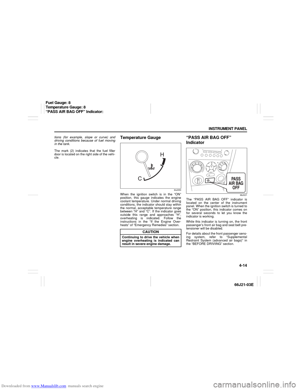
Temperature Gauge
64J053
When the ignition switch is in the “ON”
position, this gauge indicates the engine
coolant temperature. Under normal driving
conditions, the indicator should stay within
the normal, acceptable temperature range
between “H” and “C”. If the indicator goes
outside this range and approaches “H”,
overheating is indicated. Follow the
instructions in the “If the Engine Over-
heats” of “Emergency Remedies” section.
“PASS AIR BAG OFF”
Indicator
66J021
The “PASS AIR BAG OFF” indicator is
located on the center of the instrument
panel. When the ignition switch is turned to
the “ON” position, this indicator comes on
for several seconds to let you know the
indicator is working.
While this indicator is turning on, the front
passenger’s front air bag and seat belt pre-
tensioner will be disabled.
For details about the front passenger sens-
ing system, refer to “Supplemental
Restraint System (advanced air bags)” in
the “BEFORE DRIVIING” section.
CAUTION
Continuing to drive the vehicle when
engine overheating is indicated can
result in severe engine damage.
Fuel Gauge: 8
Temperature Gauge: 8
“PASS AIR BAG OFF” Indicator:
Page 82 of 211
Downloaded from www.Manualslib.com manuals search engine 4-20 INSTRUMENT PANEL
66J21-03E
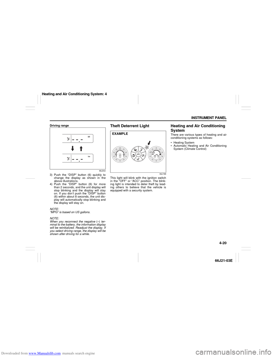
Driving range
66J202
3) Push the “DISP” button (6) quickly to
change the display as shown in the
above illustrations.
4) Push the “DISP” button (6) for more
than 2 seconds, and the unit display will
stop blinking and the display will stay
on. If you don’t push the “DISP” button
(6) within about 8 seconds, the unit dis-
play will automatically stop blinking and
the display will stay on.
NOTE:
“MPG” is based on US gallons.
NOTE:
When you reconnect the negative (–) ter-
minal to the battery, the information display
will be reinitialized. Readjust the display. If
you select driving range, the display will be
shown after driving for a while.
Theft Deterrent Light
66J188
This light will blink with the ignition switch
in the “OFF” or “ACC” position. The blink-
ing light is intended to deter theft by lead-
ing others to believe that the vehicle is
equipped with a security system.
Heating and Air Conditioning
SystemThere are various types of heating and air
conditioning systems as follows:
Heating System
Automatic Heating and Air Conditioning
System (Climate Control)
EXAMPLE
Heating and Air Conditioning System: 4
Page 83 of 211
Downloaded from www.Manualslib.com manuals search engine 4-21 INSTRUMENT PANEL
66J21-03E
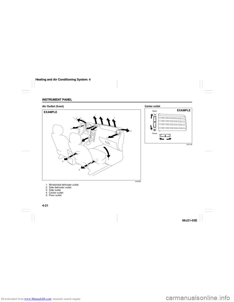
Air Outlet (front)
64J066
1. Windshield defroster outlet
2. Side defroster outlet
3. Side outlet
4. Center outlet
5. Floor outlet
1
1
2
2
3 3
5 5
5 54
EXAMPLE
Center outlet
64J199
CloseOpen
EXAMPLE
Heating and Air Conditioning System: 4
Page 84 of 211

Downloaded from www.Manualslib.com manuals search engine 4-22 INSTRUMENT PANEL
66J21-03E
Side outlet
63J045
When “Open”, air comes out from the side
outlets regardless of the air flow selector
position.
Heating SystemDescription of Controls
64J067
Temperature selector (1)
This is used to select the temperature by
turning the selector.
Blower speed selector/Air intake selec-
tor (2)
This is used to turn on the blower and to
select blower speed by turning the selec-
tor.
Also, this is used to select the following
modes by pushing the selector.
64J134
RECIRCULATED AIR
When this mode is selected, the indicator
light (a) will come on, outside air is shut out
and inside air is recirculated. This mode is
suitable when driving through dusty or pol-
luted air such as in a tunnel, or when
attempting to quickly cool down the inte-
rior.
FRESH AIR
When this mode is selected, the indicator
light (b) will come on and outside air is
used.
“FRESH AIR” and “RECIRCULATED AIR”
are switched alternately each time the air
intake selector is pushed.
NOTE:
If the recirculation indicator light (a) blinks,
there is a problem in the heating system.
You should have the system inspected by
an authorized SUZUKI dealer.
NOTE:
If you select “RECIRCULATED AIR” for an
extended period of time, the air in the vehi-
cle can become contaminated. Therefore,
(2)
(1)
(3)
(a) (b)
Heating and Air Conditioning System: 4
Page 85 of 211
Downloaded from www.Manualslib.com manuals search engine 4-23 INSTRUMENT PANEL
66J21-03E
you should occasionally select “FRESH
AIR”.
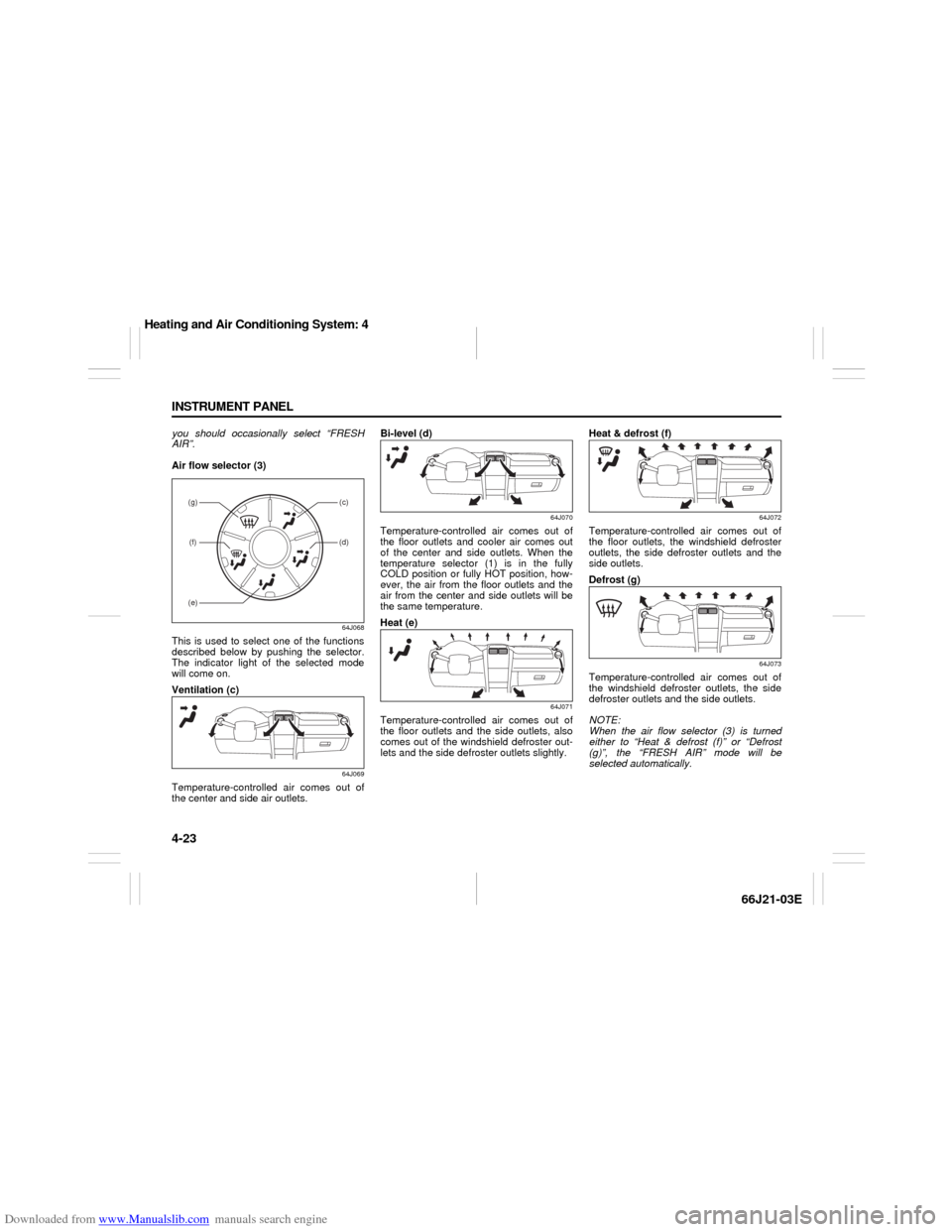
Air flow selector (3)
64J068
This is used to select one of the functions
described below by pushing the selector.
The indicator light of the selected mode
will come on.
Ventilation (c)
64J069
Temperature-controlled air comes out of
the center and side air outlets.Bi-level (d)
64J070
Temperature-controlled air comes out of
the floor outlets and cooler air comes out
of the center and side outlets. When the
temperature selector (1) is in the fully
COLD position or fully HOT position, how-
ever, the air from the floor outlets and the
air from the center and side outlets will be
the same temperature.
Heat (e)
64J071
Temperature-controlled air comes out of
the floor outlets and the side outlets, also
comes out of the windshield defroster out-
lets and the side defroster outlets slightly.Heat & defrost (f)
64J072
Temperature-controlled air comes out of
the floor outlets, the windshield defroster
outlets, the side defroster outlets and the
side outlets.
Defrost (g)
64J073
Temperature-controlled air comes out of
the windshield defroster outlets, the side
defroster outlets and the side outlets.
NOTE:
When the air flow selector (3) is turned
either to “Heat & defrost (f)” or “Defrost
(g)”, the “FRESH AIR” mode will be
selected automatically.
(g)(f)
(c)(d)
(e)
Heating and Air Conditioning System: 4
Page 86 of 211
Downloaded from www.Manualslib.com manuals search engine 4-24 INSTRUMENT PANEL
66J21-03E
System Operating InstructionsNatural ventilation
Select “VENTILATION” and “FRESH AIR”,
the temperature selector to the desired
temperature position, and the blower
speed selector to “OFF”. Fresh air will flow
through the vehicle during driving.
Forced ventilation
The control settings are the same as for
natural ventilation except you set the
blower speed selector to a position other
than “OFF”.
Normal heating (using outside air)
Select “HEAT” and “FRESH AIR”, the tem-
perature selector to the desired tempera-
ture position and the blower speed selector
to the desired blower speed position. Set-
ting the blower speed selector to a higher
blower speed position increases heating
efficiency.
Quick heating (using recirculated air)
The control settings are the same as for
normal heating except you select “RECIR-
CULATED AIR”. If you use this heating
method for an extended period of time, the
air in the vehicle can become contami-
nated and the windows can become misty.
Therefore, use this method only for quick
heating and change to the normal heating
method as soon as possible.
Head cooled/Feet warmed heating
Select “BI-LEVEL” and “FRESH AIR”, the
temperature selector to the desired tem-perature position, and the blower speed
selector to the desired blower speed posi-
tion. Unless the temperature selector is in
the fully COLD position or fully HOT posi-
tion, the air that comes out of the center
and side outlets will be cooler than the air
that comes out of the floor outlets.
Defrosting/Feet warmed heating
Select “HEAT & DEFROST” and “FRESH
AIR”, the temperature selector to the
desired temperature position, and the
blower speed selector to HIGH. When the
windshield has become clear, set the
blower speed selector to the desired
blower speed position.
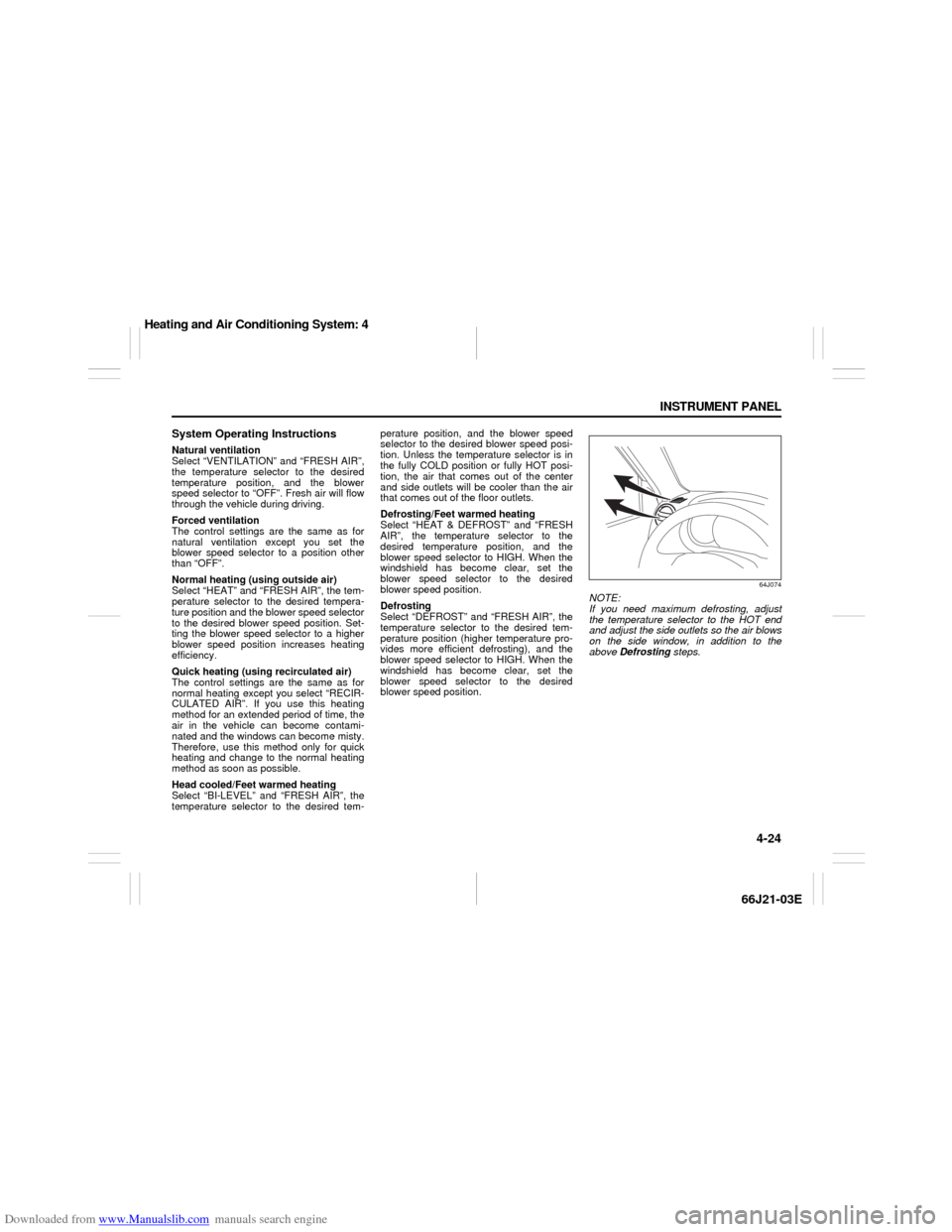
Defrosting
Select “DEFROST” and “FRESH AIR”, the
temperature selector to the desired tem-
perature position (higher temperature pro-
vides more efficient defrosting), and the
blower speed selector to HIGH. When the
windshield has become clear, set the
blower speed selector to the desired
blower speed position.
64J074
NOTE:
If you need maximum defrosting, adjust
the temperature selector to the HOT end
and adjust the side outlets so the air blows
on the side window, in addition to the
above Defrosting steps.
Heating and Air Conditioning System: 4