2007 SUZUKI FORENZA battery
[x] Cancel search: batteryPage 167 of 225

5-23 SERVICE AND APPEARANCE CARE
85Z03-03E
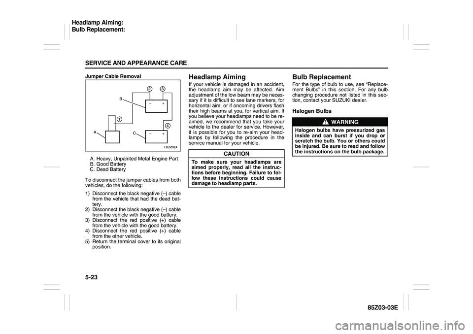
Jumper Cable Removal
A. Heavy, Unpainted Metal Engine Part
B. Good Battery
C. Dead Battery
To disconnect the jumper cables from both
vehicles, do the following:
1) Disconnect the black negative (–) cable
from the vehicle that had the dead bat-
tery.
2) Disconnect the black negative (–) cable
from the vehicle with the good battery.
3) Disconnect the red positive (+) cable
from the vehicle with the good battery.
4) Disconnect the red positive (+) cable
from the other vehicle.
5) Return the terminal cover to its original
position.
Headlamp AimingIf your vehicle is damaged in an accident,
the headlamp aim may be affected. Aim
adjustment of the low beam may be neces-
sary if it is difficult to see lane markers, for
horizontal aim, or if oncoming drivers flash
their high beams at you, for vertical aim. If
you believe your headlamps need to be re-
aimed, we recommend that you take your
vehicle to the dealer for service. However,
it is possible for you to re-aim your head-
lamps by following the procedure in the
service manual for your vehicle.
Bulb ReplacementFor the type of bulb to use, see “Replace-
ment Bulbs” in this section. For any bulb
changing procedure not listed in this sec-
tion, contact your SUZUKI dealer.Halogen Bulbs
CAUTION
To make sure your headlamps are
aimed properly, read all the instruc-
tions before beginning. Failure to fol-
low these instructions could cause
damage to headlamp parts.
WARNING
Halogen bulbs have pressurized gas
inside and can burst if you drop or
scratch the bulb. You or others could
be injured. Be sure to read and follow
the instructions on the bulb package.
Headlamp Aiming:
Bulb Replacement:
Page 176 of 225

5-32 SERVICE AND APPEARANCE CARE
85Z03-03E
mounted on a vehicle. The side of the tire
that contains a whitewall, bears white let-
tering or bears manufacturer, brand and or
model name molding that is higher or
deeper than the same moldings on the
other sidewall of the tire.
Passenger (P-Metric) Tire:
A tire used on passenger cars and some
light duty trucks and multipurpose vehicles.
Production Options Weight:
The combined weight of those installed
regular production options weighing over
2.3 kilograms in excess of those standard
items which they replace, not previously
considered in curb weight or accessory
weight, including heavy duty brakes, ride
levelers, roof rack, heavy duty battery, and
special trim.
Recommended Inflation Pressure:
Vehicle manufacturer’s recommended tire
inflation pressure shown on the tire plac-
ard.
Radial Ply Tire:
A pneumatic tire in which the ply cords that
extend to the beads are laid at 90 degrees
to the centerline of the tread.
Rim:
A metal support for a tire and upon which
the tire beads are seated.
Sidewall:
The portion of a tire between the tread and
the bead.Speed Rating:
An alphanumeric code assigned to a tire
indicating the maximum speed at which a
tire can operate.
Traction:
The friction between the tire and the road
surface. The amount of grip provided.
Tread:
The portion of a tire that comes into con-
tact with the road.
Tread wear Indicators:
Narrow bands, sometimes called “wear
bars,” that show across the tread of a tire
when only 2/32 inch of tread remains.
UTQGS:
Uniform Tire Quality Grading Standards, a
tire information system that provides con-
sumers with ratings for a tire’s traction,
temperature and tread wear. Ratings are
determined by tire manufacturers using
government testing procedures. The rat-
ings are molded into the sidewall of the
tire.
Vehicle Capacity Weight:
The number of designated seating posi-
tions multiplied by 150 lbs (68 kg) plus the
rated cargo load.
Vehicle Maximum Load on the Tire:
The load on an individual tire that is deter-
mined by distributing to each axle its share
of the maximum loaded vehicle weight and
dividing by two.Vehicle Normal Load on the Tire:
The load on an individual tire that is deter-
mined by distributing to each axle its share
of the curb weight, accessory weight, and
normal occupant weight (distributed in
accordance with Table 1 shown below) and
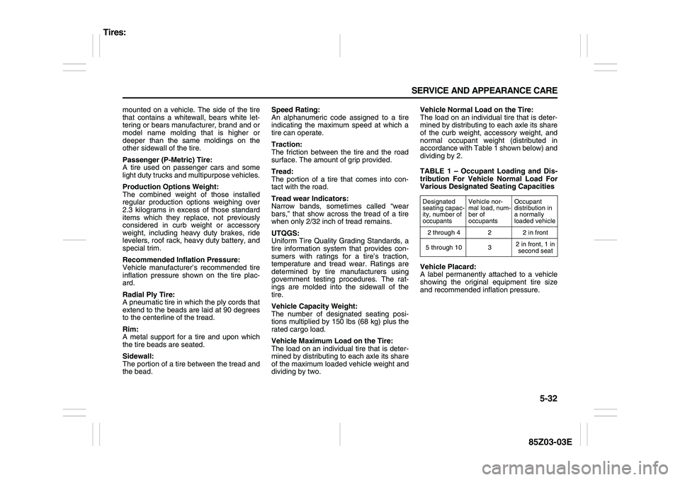
dividing by 2.
TABLE 1 – Occupant Loading and Dis-
tribution For Vehicle Normal Load For
Various Designated Seating Capacities
Vehicle Placard:
A label permanently attached to a vehicle
showing the original equipment tire size
and recommended inflation pressure.
Designated
seating capac-
ity, number of
occupantsVehicle nor-
mal load, num-
ber of
occupantsOccupant
distribution in
a normally
loaded vehicle
2 through 4 2 2 in front
5 through 10 32 in front, 1 in
second seat
Tires:
Page 195 of 225

5-51 SERVICE AND APPEARANCE CARE
85Z03-03E
Engine Compartment Fuse Block
The engine compartment fuse block is
located on the driver’s side of the vehicle,
near the battery. See “Engine Compart-
ment Overview” in this section for more
information on location.
To access the fuses, press in the side flaps
to release the cover.
To reinstall the cover, push until it is
secure. Fuses Usages
AIRBAG Air Bag
WPR Wiper
RADIO/CLK Radio/Clock
ECMEngine Control
Module
AIRBAGOccupation Classifi-
cation Sensor
AUX LTR Extra Jack
TRN SIG LAMPS Turn Signal Lamps
ABSAntilock Brake
System
LTR Cigar Lighter
CLSTR, BTSICluster, BTSI
Solenoid
RKERemote keyless
Entry
BCK/UP Back-up
BLANK Not Used
TCMTransmission
Control Module
Fuses Usages
ENG FUSE BOX,
DRLEngine Fuse box,
Daytime Running
Light
HAZRD LAMPS Hazard Lamps
A/C, CLK A/C Switch, Clock
HVACHeating, Ventilation
and Air Conditioning
RKERemote Keyless
Entry
RADIO Radio
S/ROOF Sunroof
DLC Data link Connector
SPARE Spare
Electrical System:
Page 197 of 225

5-53 SERVICE AND APPEARANCE CARE
85Z03-03E
Fuses Usages
HEAD LAMPS Head Lamp
ECMEngine Control
Module
I/P FUSEInstrument Panel
Fuse
FUEL PUMP Fuel Pump
A/C Air Conditioning
HORN Horn
HI BEAMHead Lamp
High-Beam
DRIVER’S PWR
WNDWDriver’s Power
Window
STOP LAMPS Stop Lamps
DR/LCK Door Lock
MIR HTD Heated Mirror
FRT FOG Front Fog
ILLUM LTLicense Plate Lamp,
Parking Lamp Left
INJ Injector
Fuses Usages
ENG SNSREVAP Canister Purge
Solenoid, HO2S,
Cooling Fan Relay,
CMP Sensor
LOW BEAM LTHead Lamp
Low-Beam Left
ILLUM RTIllumination
Circuit, Parking Lamp
Right
LOW BEAM RTHead Lamp
Low-Beam Right
SPARE Spare
SPARE Spare
SPARE Spare
BATT PWR Battery Power
ABSAntilock Brake
System
HVAC BLWR HVAC Blower
IGN 2 Ignition 2
IGN 1 Ignition 1
FUSE PLR Fuse Puller
COOL FAN LOW Cooling Fan Low
Fuses Usages
DEFOG Defog
COOL FAN HI Cooling Fan High
PWR WNDW Power Window
Relays Usages
COOL FAN LOW Cooling Fan Low
FRT FOG Front Fog
ILLUM Illumination Relay
A/C CMPRSRAir Conditioning
Compressor
HORN Horn
DEFOG Defog
FUEL PUMP Fuel Pump
MAIN Main Relay
COOL FAN HI Cooling Fan High
PWR WNDW Power Window
HEAD LAMPS Headlamp Relay
Capacities and Specifications:
Page 198 of 225

5-54 SERVICE AND APPEARANCE CARE
85Z03-03E
Capacities and SpecificationsThe following approximate capacities are
given in English and metric conversions. CapacitiesSpecifications
EngineChassis
ApplicationCapacities
English Metric
Air Conditioning
Refrigerant R-134a1.41 lbs 0.64 kg
Brake/Clutch Fluid 0.53
quarts0.5 L
Engine Coolant 7.9
quarts7.4 L
Engine Oil with Filter 4.2
quarts4.0 L
Fuel Tank 14.5
gallons55.0 L
Power Steering Fluid 1.2
quarts1.1 L
Automatic Transmis-
sion Fluid
(Complete Overhaul)7.3 ± 0.2
quarts6.9 ±
0.2 L
Manual Transmission
Fluid (Complete Drain
and Refill)1.9
quarts1.8 L
Wheel Nut Torque 81 lb-ft 110 N.m
All capacities are approximate. When
adding, be sure to fill to the approximately
level, as recommended in this manual. Engine 2.0 L DOHC (L6)
VIN Code Z
Type 4-Cylinder / In-Line
Valve Train DOHC 16 Valve
Displacement 121.9 in
3 (1,998 cc)
Bore x stroke 3.39 in x 3.39 in
(86 mm x 86 mm)
Compression Ratio 9.6 : 1
Octane Rating 87 (Ron 91) or
higher
Spark
plugType FLR8LDCU
Gap 0.039 in (1.0 mm)
Battery Rating 12V – 55AH
Cold
Cranking
Ampere610 CCA
Front Suspension Type McPherson
Strut Type
Rear Suspension Type Dual Link
Type
Alignment
(Curb
Weight)Front Camber –0°33’ ± 45’
Rear Camber –1°00’ ± 45’
Caster 4°00’ ± 45’
Front Toe-in 0°00’ ± 10’
Rear Toe-in 0°12’ ± 10’
Page 220 of 225

8-1 INDEX
88
85Z03-03E
INDEXAAccessory Power Outlet
.....................................................3-11
Adding Equipment to the Outside of Your Vehicle
..........5-1
Adding Equipment to Your Air Bag-Equipped Vehicle
....1-32
Additives
..............................................................................5-2
Add-On Electrical Equipment
.............................................5-49
Air Bag Readiness Light
.....................................................3-20
Antenna
................................................................................2-25
Anti-Lock Brake System (ABS)
..........................................4-3
Anti-Lock Brake System Warning Light
............................3-21
Appearance Care
.................................................................5-45
Ashtrays and Cigarette Lighter
..........................................3-11
Audio System
.......................................................................3-28
Automatic Transmission Fluid
...........................................5-10
Automatic Transmission Operation
...................................2-13
BBattery
..................................................................................5-20
Before Driving
......................................................................2-11
Before Leaving on a Long Trip
...........................................4-11
Brake System Warning Light
..............................................3-21
Brakes
...................................................................................5-18
Braking .................................................................................4-3
Bulb Replacement
...............................................................5-23
Buying New Tires ................................................................5-37
CCalifornia Fuel
......................................................................5-1
Capacities
.............................................................................5-54
Capacities and Specifications
............................................5-54CD CHANGER OPERATION (Optional)
............................. 3-44
Center High-Mounted Stop Lamp (Sedan) ........................ 5-25
Center High-Mounted Stop Lamp (Wagon) ...................... 5-25
Central Door Locking System
............................................ 2-5
Changing a Flat Tire
........................................................... 5-39
Charging System Light ....................................................... 3-20
Checking Things Under the Hood
..................................... 5-4
Checking Your Restraint Systems .................................... 1-34
Chemical Paint Spotting
..................................................... 5-48
Child Restraint Systems ..................................................... 1-19
Child Restraints
.................................................................. 1-16
City Driving
.......................................................................... 4-10
Cleaning the Inside of Your Vehicle
.................................. 5-45
Cleaning the Outside of Your Vehicle ............................... 5-46
Climate Control System
..................................................... 3-13
Climate Controls
................................................................. 3-13
Clock
.................................................................................... 3-12
Control of a Vehicle
............................................................ 4-2
Coolant Surge Tank Pressure Cap
.................................... 5-14
Cooling System
................................................................... 5-15
Correcting the Tire Pressure
............................................. 5-34
Cruise Control
..................................................................... 3-7
Cruise Control Light
........................................................... 3-25
Cupholder(s)
........................................................................ 2-22
DDaily Inspection Checklist
................................................. 2-11
Daytime Running Lamps Indicator Light
.......................... 3-26
Defensive Driving
................................................................ 4-1