2007 SUBARU IMPREZA clock
[x] Cancel search: clockPage 67 of 364

1-42Seat, seatbelt and SRS airbags
. Do not apply any strong impact to the
front passenger ’s seat such as by kicking.
. Do not spill liquid on the front passen-
ger ’s seat. If liquid is spilled, wipe it off
immediately. . Do not remove or disassemble the front
passenger ’s seat.
. Do not install any accessory (such as
an audio amplifier) other than a genuine
SUBARU accessory under the front pas-senger ’s seat.
. Do not place anything (shoes, umbrel-
la, etc.) under the front passenger ’s seat.
. The front passenger ’s seat must not be
used with the head restraint removed. . Do not leave any article including a
child restraint system on the front passen- ger ’s seat or the seatbelt tongue and
buckle engaged when you leave yourvehicle. . Do not place a magnet near the
seatbelt buckle and the seatbelt retractor.. Do not use front seats with their back-
ward-forward position and seatback not
being locked into place securely. If any of
them are not locked securely, adjust them
again. For adjusting procedure, refer tothe “Front seats ”section in this chapter.
. If you use an optional seatbelt exten-
der, remove it after each use. (Refer to the“ Seatbelt extender ”section in this chap- ter.)
If the seatbelt buckle switch and/or front passenger
’s occupant detection system
have failed, the SRS airbag system
warning light will illuminate. Have the
system inspected by your SUBARU deal-
er immediately if the SRS airbag system
warning light comes on.
If your vehicle has sustained impact, this
may affect the proper function of the
Subaru advanced frontal airbag system.
Have your vehicle inspected at your
SUBARU dealer.
NOTE
The front passenger ’s SRS side airbag
and seatbelt pretensioner are not con-
trolled by the Subaru advanced frontal
airbag system. !
Passenger ’s frontal airbag ON and
OFF indicators
ON or: Front passenger ’s frontal airbag
ON indicator
or: Front passenger ’s frontal airbag
OFF indicator
The front passenger ’s frontal airbag ON
and OFF indicators show you the status of
the front passenger ’s SRS frontal airbag.
The indicators are located next to the
clock in the center portion of the dash-board.
When the ignition switch is turned to the “ ON ”position, both the ON and OFF
indicators illuminate for 6 seconds during
which time the system is checked. Follow-
ing the system check, both indicators
extinguish for 2 seconds. After that, one
of the indicators illuminates depending on
Page 104 of 364

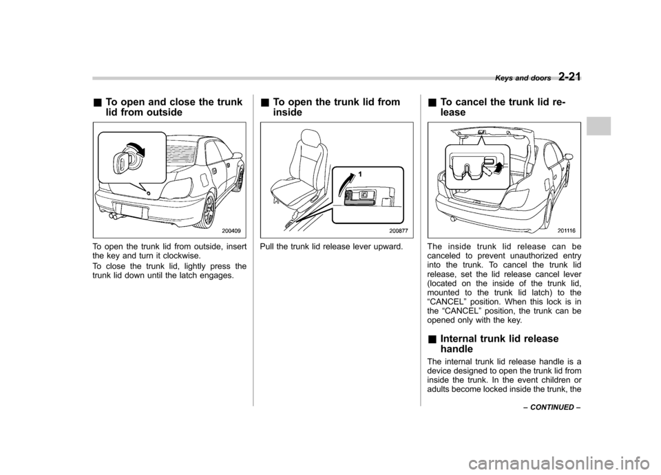
&To open and close the trunk
lid from outside
To open the trunk lid from outside, insert
the key and turn it clockwise.
To close the trunk lid, lightly press the
trunk lid down until the latch engages. &
To open the trunk lid from insidePull the trunk lid release lever upward. &
To cancel the trunk lid re- leaseTheinsidetrunklidreleasecanbe
canceled to prevent unauthorized entry
into the trunk. To cancel the trunk lid
release, set the lid release cancel lever
(located on the inside of the trunk lid,
mounted to the trunk lid latch) to the“CANCEL ”position. When this lock is in
the “CANCEL ”position, the trunk can be
opened only with the key. & Internal trunk lid release handle
The internal trunk lid release handle is a
device designed to open the trunk lid from
inside the trunk. In the event children or
adults become locked inside the trunk, the Keys and doors
2-21
– CONTINUED –
Page 110 of 364

Ignition switch..................................................... 3-3
LOCK .................................................................. 3-3
Acc..................................................................... 3-4
ON...................................................................... 3-4
START ................................................................ 3-4
Key reminder chime ............................................ 3-5
Ignition switch light ............................................. 3-5
Key interlock release (AT vehicles only) ... ............ 3-5
Hazard warning flasher ....................................... 3-6
Meters and gauges (WRX-STI) ........................... 3-6
Combination meter illumination ........................... 3-6
Canceling sequential illumination of the combination meter ............................................ 3-6
Speedometer ....................................................... 3-7
Odometer/Trip meter ............................................ 3-7
Tachometer ......................................................... 3-7
Fuel gauge .......................................................... 3-8
Temperature gauge ............................................. 3-8
Outside temperature indicator ............................. 3-9
REV indicator light and buzzer (WRX-STI) ........ 3-9
Setting the alarm-level engine speed ................... 3-10
Deactivating the REV alarm system ..................... 3-11
Meters and gauges (Except WRX-STI) .............. 3-11
Speedometer ...................................................... 3-11
Odometer/Trip meter ........................................... 3-11
Tachometer ........................................................ 3-12
Fuel gauge ......................................................... 3-12
Temperature gauge ............................................ 3-13
Outside temperature indicator ............................ 3-13
Warning and indicator lights ............................. 3-14
Seatbelt warning light and chime ........................ 3-14SRS airbag system warning light
........................ 3-14
Front passenger ’s frontal airbag ON and OFF
indicators ........................................................ 3-15
CHECK ENGINE warning light/Malfunction indicator lamp ................................................. 3-16
Charge warning light .......................................... 3-16
Oil pressure warning light .................................. 3-16
AT OIL TEMPerature warning light (AT vehicles) .................................................... 3-17
Rear differential oil temperature warning light (WRX-STI) ........................................................ 3-17
ABS warning light .............................................. 3-17
Brake system warning light ................................ 3-18
Door open warning light .................................... 3-19
All-Wheel Drive warning light (AWD AT vehicles –
if equipped) ..................................................... 3-19
Intercooler water spray warning light (WRX-STI) ........................................................ 3-19
Selector lever position indicator (AT vehicles) .................................................... 3-20
Turn signal indicator lights ................................. 3-20
High beam indicator light ................................... 3-20
Cruise control indicator light .............................. 3-20
Cruise control set indicator light ........................ 3-20
Driver ’s control center differential auto indicator
light (WRX-STI) ................................................ 3-20
Driver ’s control center differential indicator and
warning lights (WRX-STI) ................................. 3-21
Lights indicator light (WRX-STI) ......................... 3-21
REV indicator light (WRX-STI) .. .......................... 3-21
Clock .................................................................. 3-22Instruments and controls
3
Page 115 of 364

3-6Instruments and controls
Hazard warning flasher
The hazard warning flasher is used to
warn other drivers when you have to park
your vehicle under emergency conditions.
The hazard warning flasher works with the
ignition switch in any position.
To turn on the hazard warning flasher,
push the hazard warning button on the
instrument panel. To turn off the flasher,
push the button again. NOTE
When the hazard warning flasher is on,
the turn signals do not work. Meters and gauges (WRX- STI) NOTE
Liquid-crystal displays are used in
some of the meters and gauges in the
combination meter. You will find their
indications hard to see if you wear
polarized glasses. &
Combination meter illumina- tion
When the ignition switch is turned to the “ ON ”position, the various parts of the
combination meter are illuminated in the
following sequence:
1. Meter needles and gauge needles
light up.
2. Meter needles and gauge needles
each show MAX position.
3. Meter needles and gauge needles
each show MIN position, and REV indi-
cator flashes.
4. Dials and indicators in meters and
gauges light up. 5. “STI ”mark lights up.
6. Regular illumination (for driving) be- gins. &
Canceling sequential illumi-
nation of the combination meter
With the ignition switch in the “ON ”
position, it is possible to cancel sequential
illumination of the combination meter.
Press the trip knob while turning the REV
setting knob clockwise or counterclock-
wise. The buzzer will sound briefly, and
the outside temperature indicator willshow “ON ”or “– –” .
ON : sequential illumination –– : sequential illumination canceled
The setting toggles between “ON ”and “–
–” each time the trip knob is pressed.
Return the REV setting knob to its original
position to complete the setting process.
The buzzer will sound briefly. A few
seconds later, the outside temperature
indicator will return to showing the outsidetemperature. NOTE
It is not possible to cancel sequential
illumination of the combination meter
while sequential illumination is actually
taking place. Cancel sequential illumi-
nation when regular illumination (for
driving) has begun.
Page 119 of 364

3-10Instruments and controls
NOTE
Even if the REV alarm system is not set,
the REV indicator light will come on
whenever the engine speed enters thetachometer ’s red zone.
& Setting the alarm-level en-
gine speed
1. Turn the REV setting knob clockwise
or counterclockwise, then release it and
let it return to its initial position. The buzzer
will sound. The REV alarm system is now
ready to be set.
2. Turn the REV setting knob to select
the desired alarm-level engine speed.
At this time, the outside temperature
indicator will show the engine-speed setting. .
Counterclockwise ( �): Speed setting
changes downward by 100 rpm. . Clockwise (+): Speed setting
changes upward by 100 rpm.
The speed setting will stop changing if
it reaches 0 rpm or the maximum
engine speed.
The alarm-level engine speed can be set
(in 100 rpm steps) within the range from
2,000 rpm to 7,000 rpm.
The indicator shows the setting as follows:
Speed (rpm) Indication 00 0
2,000 20
2,100 21 ––
7,000 70
Approximately 3 seconds after you stop
turning the knob, the REV alarm system
will automatically enter its next setting
mode (step 3 below), in which you can
activate or deactivate the buzzer.
3. Activate or deactivate the buzzer as
desired using the REV setting knob. .Turn the knob clockwise (+) to
activate the buzzer. The indicator willshow “ON ”, and the buzzer will sound three times. With the buzzer activated,
engine-speed warnings are given by
both the REV indicator light and the
buzzer. .
Turn the knob counterclockwise ( �)
to deactivate the buzzer. The indicator
will show “– –”, and the buzzer will not
sound. With the buzzer deactivated,
engine-speed warnings are given only
by the REV indicator light.
Approximately 3 seconds after you stop
turning the knob, the buzzer will sound
once to indicate the end of the setting
procedure. The indicator will return to
showing the outside temperature.
Also, the tachometer needle will return to approximately “0 ”.
NOTE . The REV alarm system does not
operate while settings are being en- tered.. The speed-setting mode terminates
if 0 rpm is selected.. The speed-setting mode is canceled
if the ignition switch is turned to OFF or
the vehicle starts moving before the
setting procedure is finished.. Speed setting is impossible when
the vehicle is moving.. The set engine speed may differ
Page 124 of 364

“ON ”position, the SRS airbag system
warning light will come on for approxi-
mately 6 seconds and go out. This shows
the SRS airbag and SRS side airbag (if
equipped) and seatbelt pretensioners are
in normal operation.
WARNING
If the warning light exhibits any of
the following conditions, there may
be a malfunction in the seatbelt
pretensioners and/or SRS airbag
system. Immediately take your vehi-
cle to your nearest SUBARU dealer
to have the system checked. Unless
checked and properly repaired, the
seatbelt pretensioners and/or SRS
airbag will not operate properly in
the event of a collision, which may
increase the risk of injury. . Flashing or flickering of the warn-
ing light
. No illumination of the warning
light when the ignition switch is
first turned to the “ON ”position
. Continuous illumination of the
warning light
. Illumination of the warning light
while driving &
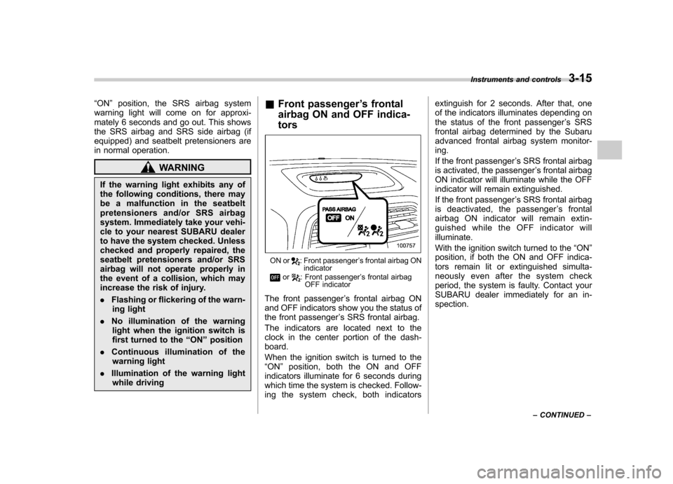
Front passenger ’s frontal
airbag ON and OFF indica- tors
ON or: Front passenger ’s frontal airbag ON
indicator
or: Front passenger ’s frontal airbag
OFF indicator
The front passenger ’s frontal airbag ON
and OFF indicators show you the status of
the front passenger ’s SRS frontal airbag.
The indicators are located next to the
clock in the center portion of the dash-board.
When the ignition switch is turned to the “ ON ”position, both the ON and OFF
indicators illuminate for 6 seconds during
which time the system is checked. Follow-
ing the system check, both indicators extinguish for 2 seconds. After that, one
of the indicators illuminates depending on
the status of the front passenger
’s SRS
frontal airbag determined by the Subaru
advanced frontal airbag system monitor-ing.
If the front passenger ’s SRS frontal airbag
is activated, the passenger ’s frontal airbag
ON indicator will illuminate while the OFF
indicator will remain extinguished.
If the front passenger ’s SRS frontal airbag
is deactivated, the passenger ’s frontal
airbag ON indicator will remain extin-
guished while the OFF indicator willilluminate.
With the ignition switch turned to the “ON ”
position, if both the ON and OFF indica-
tors remain lit or extinguished simulta-
neously even after the system check
period, the system is faulty. Contact your
SUBARU dealer immediately for an in-spection. Instruments and controls
3-15
– CONTINUED –
Page 131 of 364

3-22Instruments and controls
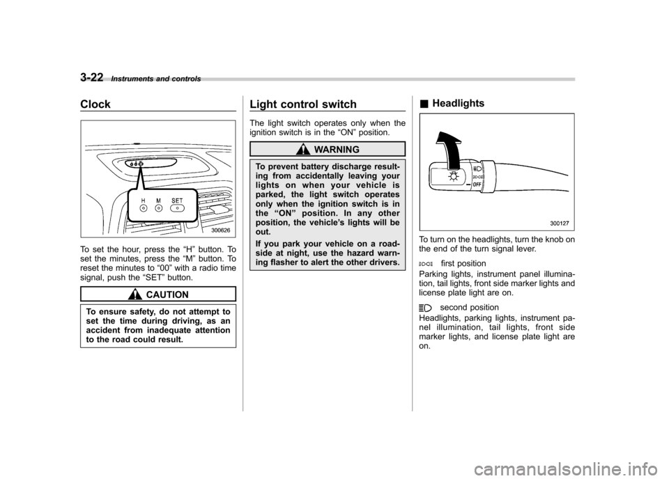
Clock
To set the hour, press the “H ” button. To
set the minutes, press the “M ”button. To
reset the minutes to “00 ”with a radio time
signal, push the “SET ”button.
CAUTION
To ensure safety, do not attempt to
set the time during driving, as an
accident from inadequate attention
to the road could result. Light control switch
The light switch operates only when the
ignition switch is in the
“ON ”position.
WARNING
To prevent battery discharge result-
ing from accidentally leaving your
lights on when your vehicle is
parked, the light switch operates
only when the ignition switch is inthe “ON ”position. In any other
position, the vehicle ’s lights will be
out.
If you park your vehicle on a road-
side at night, use the hazard warn-
ing flasher to alert the other drivers. &
Headlights
To turn on the headlights, turn the knob on
the end of the turn signal lever.
first position
Parking lights, instrument panel illumina-
tion, tail lights, front side marker lights and
license plate light are on.
second position
Headlights, parking lights, instrument pa-
nel illumination, tail lights, front side
marker lights, and license plate light areon.
Page 138 of 364

To turn the wiper off, return the knob to the “OFF ”position.
! Washer
To wash the rear window while the rear
wiper is operating, turn the knob clockwise
to the “
”position. The washer fluid
sprays until you release the knob.
To wash the rear window when the rear
wiper is not in use, turn the knob counter-
clockwise to the “
”position. The washer
fluid sprays and the wiper operates until
you release the knob. Rear window defogger but- ton
The rear window defogger operates only
when the ignition switch is in the
“ON ”
position.
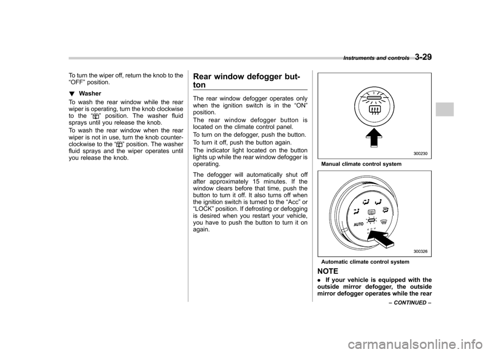
The rear window defogger button is
located on the climate control panel.
To turn on the defogger, push the button.
To turn it off, push the button again.
The indicator light located on the button
lights up while the rear window defogger isoperating.
The defogger will automatically shut off
after approximately 15 minutes. If the
window clears before that time, push the
button to turn it off. It also turns off when
the ignition switch is turned to the “Acc ”or
“ LOCK ”position. If defrosting or defogging
is desired when you restart your vehicle,
you have to push the button to turn it onagain.
Manual climate control system
Automatic climate control system
NOTE . If your vehicle is equipped with the
outside mirror defogger, the outside
mirror defogger operates while the rear Instruments and controls
3-29
– CONTINUED –