Page 270 of 364
9-16In case of emergency
Maintenance tools
Your vehicle is equipped with the following
maintenance tools:
Wheel cover remover (only for vehicleswith wheel covers)
Screwdriver
Towing hook (eye bolt)
Wheel nut wrench
Hex-head wrench (only for vehicles with moonroof) &
Jack and jack handle
The jack is stored on the left side of the
trunk (Sedan) or cargo area (Wagon).
To take out the jack, turn the jackscrew
counterclockwise to loosen it, then re-
move the jack.
Sedan
1) Jack
2) Jack handle
3) Spare tire
Page 315 of 364
1) Metal spines
2. If the new blade rubber is not provided
with two metal spines, remove the metal
spines from the old blade rubber and
install them in the new blade rubber.
3. Align the claws of the metal support with the grooves in the rubber and slide
the blade rubber assembly into the metal
support until it locks.
1) Stopper
4. Be sure to position the claws at the
end of the metal support between the
stoppers on the rubber as shown. If the
rubber is not retained properly, the wiper
blade may scratch the windshield. &
Rear window wiper blade assembly
1. Raise the wiper arm off the rear
window.
2. Turn the wiper blade assembly coun- terclockwise. Maintenance and service
11-39
– CONTINUED –
Page 324 of 364
11-48Maintenance and service
!Right-hand low beam light bulb
1. Remove the bulb cover, by turning it counterclockwise.
2. Disconnect the electrical connector.
3. Remove the retainer spring.
4. Replace the bulb with a new one.
5. Set the retainer spring securely.
6. Reconnect the electrical connector.
7. Install the bulb cover. !Left-hand low beam light bulb
WARNING
Replacement of the left-hand low
beam light bulb requires removal of
the battery and is thus dangerous. It
must be performed by a SUBARU
dealer. !
High beam light bulbs
1. Disconnect the electrical connector
from the bulb.
2. Remove the bulb from the headlight
assembly by turning it counterclockwise.
Page 325 of 364

3. Replace the bulb with a new one.
4. Reconnect the electrical connector. At
this time, use care not to touch the bulbsurface.
5. To install the bulb to the headlight
assembly, turn it clockwise until it clicks. &Front turn signal light bulbs
It may be difficult to replace the bulbs.
Have your SUBARU dealer replace the
bulbs if necessary. & Parking light
It may be difficult to replace the bulbs.
Have your SUBARU dealer replace the
bulbs if necessary. & Front fog light
It may be difficult to replace the bulbs.
Have your SUBARU dealer replace the
bulbs if necessary. &
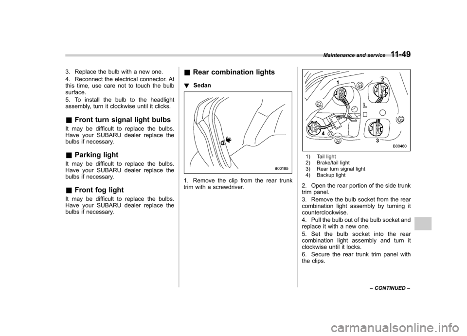
Rear combination lights
! Sedan
1. Remove the clip from the rear trunk
trim with a screwdriver.
1) Tail light
2) Brake/tail light
3) Rear turn signal light
4) Backup light
2. Open the rear portion of the side trunk
trim panel.
3. Remove the bulb socket from the rear
combination light assembly by turning itcounterclockwise.
4. Pull the bulb out of the bulb socket and
replace it with a new one.
5. Set the bulb socket into the rear
combination light assembly and turn it
clockwise until it locks.
6. Secure the rear trunk trim panel with
the clips. Maintenance and service
11-49
– CONTINUED –
Page 326 of 364
11-50Maintenance and service
! Wagon
1. Using a Phillips screwdriver, remove
the upper and lower clips that secure the
side cover of the rear combination light
assembly.
2. Remove the side cover.
3. Remove the upper and lower bolts.
Then, slide the rear combination lamp
assembly to the rear and remove it from
the vehicle.1) Brake/tail light
2) Rear turn signal light
3) Backup light
4. Remove the bulb socket from the rear
combination light assembly by turning itcounterclockwise.
5. Pull the bulb out of the bulb socket and
replace it with a new one.
6. Set the bulb socket into the rear
combination light assembly and turn it
clockwise until it locks.
Page 328 of 364
11-52Maintenance and service
1. Remove the lens by prying the edge of
the lens with a flat-head screwdriver.
2. Pull the bulb out of the socket. Install a
new bulb.
3. Reinstall the lens. &
Trunk light
1. Remove the cover by squeezing its
sides and pulling it.
2. Pull the bulb out of the socket. Install a
new bulb.
3. Reinstall the cover. &
High mount stop light
! Sedan
1. Remove the high mount stop light
cover by prying the edge with a screw-
driver.
2. Remove the bulb socket from the high
mount stop light assembly by turning itcounterclockwise.
3. Pull the bulb out of the socket. Install a
new bulb.
4. Reinstall the cover.
Page 337 of 364
12-8Specifications
&Fuse panel located in the engine compartment
A) FWD socket (AT models except Turbo)
B) Main fuse
C) Engine sensor (Non-turbo models) Fuse
panel Fuse
rating Circuit
1 20A .Radiator cooling fan
(Main)
2 20A .Radiator cooling fan
(Sub)
3 30A .ABS motor
4 20A .Rear window defogger
5 15A .Hazard warning flasher
. Horn
6 15A .Turn signal lights
7 10A .Automatic transmission
control unit
8 10A .Alternator
9 15A .Headlight (right side)
10 15A .Headlight (left side)
11 20A .Lighting switch
12 20A .Clock
. Interior light
13 10A .Secondary air combina-
tion valve (Turbo models only)
Page 356 of 364

CenterConsole .................................................................. 6-4
Ventilators ............................................................... 4-3
Center and side ventilators ............................................ 4-3
Changing Flat tire ................................................................... 9-4
Oil and oil filter ...................................................... 11-9
Charge warning light .................................................. 3-16
CHECK ENGINE warning light/Malfunction indicator lamp ...................................................................... 3-16
Checking Brake pedal free play ............................................ 11-27
Brake pedal reserve distance ................................. 11-28
Clutch function ...................................................... 11-28
Clutch pedal free play ............................................ 11-28
Engine oil level ...................................................... 11-8
Fluid level ............................... 11-20, 11-24, 11-25, 11-26
Gear oil level ........................................................ 11-22
Child restraint systems ............................................... 1-22
Installation with A/ELR seatbelt ................................ 1-25
Lower and tether anchorages .................................. 1-29
Child safety .................................................................... 5
Locks ................................................................... 2-18
Chime Key ........................................................................ 3-5 Seatbelt ........................................................ 1-11, 3-14
Cleaning
Aluminum wheels ................................................... 10-3
Interior .................................................................. 10-5
Ventilation grille ..................................................... 4-11 Climate control system
Automatic ............................................................... 4-8
Manual ................................................................... 4-3
Clock ........................................................................ 3-22
Clutch Fluid ................................................................... 11-26
Pedal .................................................................. 11-28
Coat hook. .................................................................. 6-9
Coin tray .................................................................... 6-4
Cooling system ........................................................ 11-12
Corrosion protection ............................................ 8-10, 10-4
Cruise control ............................................................ 7-26
Set indicator light .................................................... 3-20
Cruise control indicator light ......................................... 3-20
Cup holder ................................................................. 6-5
Front passenger ’s.................................................... 6-5
Rear passenger ’s .................................................... 6-6
D
Daytime running light system ....................................... 3-23
Differential gear oil
Front ................................................................... 11-21
Rear ................................................................... 11-22
Dimensions ................................................................ 12-2
Disarming the system ................................................. 2-15
Disc brake pad wear warning indicators ........................ 7-21
Dome light .................................................................. 6-2
Door
Locks ..................................................................... 2-4
Open warning light. ................................................. 3-19
Drive belts ............................................................... 11-18 Index
14-3