2007 SUBARU IMPREZA roof
[x] Cancel search: roofPage 239 of 364

WARNING
. When you carry something inside
the vehicle, secure it whenever
you can to prevent it from being
thrown around inside the vehicle
during sudden stops, sharp turns
or in an accident.
. Do not pile heavy loads on the
roof. These loads raise the vehi-cle ’s center of gravity and make it
more prone to tip over.
. Secure lengthy items properly to
prevent them from shooting for-
ward and causing serious injury
during a sudden stop.
. Never exceed the maximum load
limit. If you do, some parts on
your vehicle can break, or it can
change the way your vehicle
handles. This could result in loss
of control and cause personal
injury. Also, overloading can
shorten the life of your vehicle.
. Do not place anything on the rear
shelf behind the rear seatback
(for Sedan) or the extended cargo
area cover (for Wagon). Such
items could tumble forward in
the event of a sudden stop or a
collision. This could cause ser- ious injury.
CAUTION
Do not carry spray cans, containers
with flammable or corrosive liquids
or any other dangerous items inside
the vehicle.
NOTE
For better fuel economy, do not carry
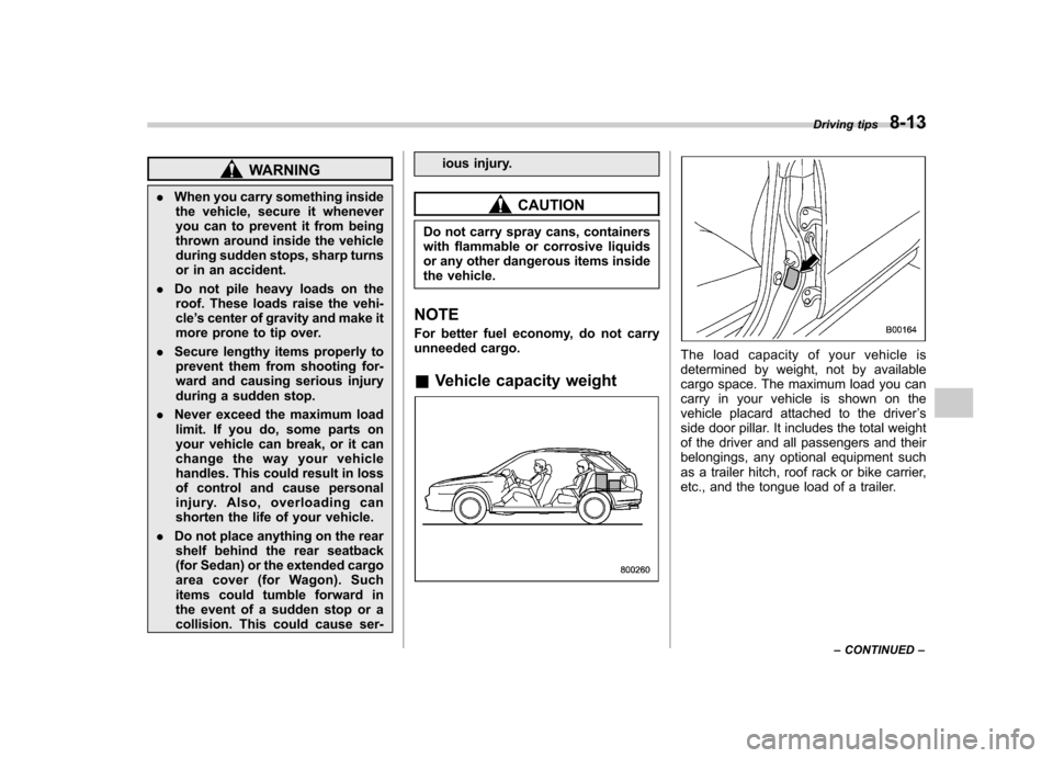
unneeded cargo. & Vehicle capacity weight
The load capacity of your vehicle is
determined by weight, not by available
cargo space. The maximum load you can
carry in your vehicle is shown on the
vehicle placard attached to the driver ’s
side door pillar. It includes the total weight
of the driver and all passengers and their
belongings, any optional equipment such
as a trailer hitch, roof rack or bike carrier,
etc., and the tongue load of a trailer. Driving tips
8-13
– CONTINUED –
Page 240 of 364

8-14Driving tips
& GVWR and GAWR (Gross
Vehicle Weight Rating and
Gross Axle Weight Rating)
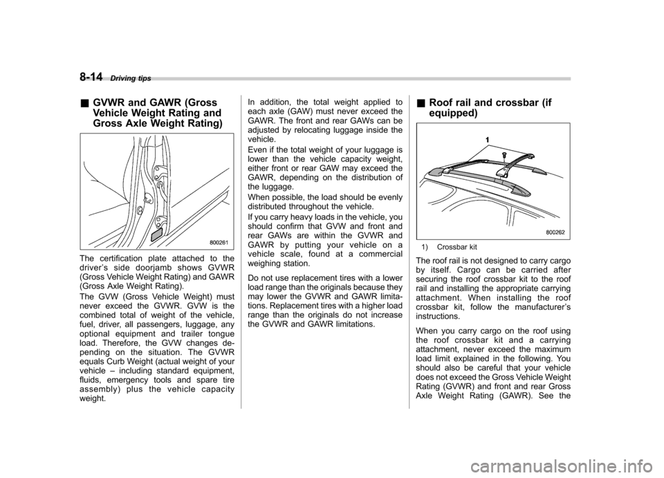
The certification plate attached to the driver ’s side doorjamb shows GVWR
(Gross Vehicle Weight Rating) and GAWR
(Gross Axle Weight Rating).
The GVW (Gross Vehicle Weight) must
never exceed the GVWR. GVW is the
combined total of weight of the vehicle,
fuel, driver, all passengers, luggage, any
optional equipment and trailer tongue
load. Therefore, the GVW changes de-
pending on the situation. The GVWR
equals Curb Weight (actual weight of yourvehicle –including standard equipment,
fluids, emergency tools and spare tire
assembly) plus the vehicle capacityweight. In addition, the total weight applied to
each axle (GAW) must never exceed the
GAWR. The front and rear GAWs can be
adjusted by relocating luggage inside thevehicle.
Even if the total weight of your luggage is
lower than the vehicle capacity weight,
either front or rear GAW may exceed the
GAWR, depending on the distribution of
the luggage.
When possible, the load should be evenly
distributed throughout the vehicle.
If you carry heavy loads in the vehicle, you
should confirm that GVW and front and
rear GAWs are within the GVWR and
GAWR by putting your vehicle on a
vehicle scale, found at a commercial
weighing station.
Do not use replacement tires with a lower
load range than the originals because they
may lower the GVWR and GAWR limita-
tions. Replacement tires with a higher load
range than the originals do not increase
the GVWR and GAWR limitations.
&
Roof rail and crossbar (if equipped)
1) Crossbar kit
The roof rail is not designed to carry cargo
by itself. Cargo can be carried after
securing the roof crossbar kit to the roof
rail and installing the appropriate carrying
attachment. When installing the roof
crossbar kit, follow the manufacturer ’s
instructions.
When you carry cargo on the roof using
the roof crossbar kit and a carrying
attachment, never exceed the maximum
load limit explained in the following. You
should also be careful that your vehicle
does not exceed the Gross Vehicle Weight
Rating (GVWR) and front and rear Gross
Axle Weight Rating (GAWR). See the
Page 241 of 364

“Loading your vehicle ”section in this
chapter for information on loading cargo
into or onto your vehicle. The maximum
load limit of the cargo, crossbars and
carrying attachment must not exceed 100
lbs (45 kg). Place the heaviest load at the
bottom, nearest the roof, and evenly
distribute the cargo. Always properly
secure all cargo.
CAUTION
. For cargo carrying purposes, the
roof rail must be used together
with a roof crossbar kit and the
appropriate carrying attachment.
The roof rail must never be used
alone to carry cargo. Otherwise,
damage to the roof or paint or a
dangerous road hazard due to
loss of cargo could result.
. When using the roof crossbar kit,
make sure that the total weight of
the crossbars, carrying attach-
ment and cargo does not exceed
the maximum load limit. Over-
loading may cause damage to
the vehicle and create a safetyhazard. !
Installing carrying attachments on
the crossbars
When installing any carrying attachment
such as a bike carrier, ski carrier, kayak
carrier, cargo basket, etc. on the cross-
bars, follow the manufacturer ’s instruc-
tions and make sure that the attachment is
securely fixed to the crossbars. Use only
attachments designed specifically for the
crossbars. A set of crossbars is designed
to carry loads (cargo and attachment) of
not more than 100 lbs (45 kg) . Before
operating the vehicle, make sure that the
cargo is properly secured on the attach-ment. NOTE
Remember that the vehicle ’s center of
gravity is altered with the weight of the
load on the roof, thus affecting the
driving characteristics.
Drive carefully. Avoid rapid starts, hard
cornering and abrupt stops. Crosswind
effects will be increased. ! Removal and installation of the crossbars
The crossbars can be removed when you
do not use the roof to carry cargo. ! To remove the crossbar
1. Loosen and remove the T-30 torx® head screw from the top of each crossbar
end support.
2. Rotate the lower clamp on the bottom
of each end support downward approxi-
mately 90
8.
3. Carefully raise the crossbar from roofrails. ! To install the crossbar
Front crossbar:
Front crossbar has 100 LBS. Load Label
on left-hand side. Driving tips
8-15
– CONTINUED –
Page 242 of 364

8-16Driving tips
F: Front of vehicle
1) T30 torx® head screw
2) Front arrow label
3) Front crossbar
4) 100LBS load label
5) Lower clamp
6) Roof rail end support 7) Joint line
8) Front arrow label
a: 3 inches (76 mm)
1. Before placing the crossbar on the roof
rails, make sure that the T-30 torx® head
screw is removed from the top of each
crossbar end support.
2. Rotate the lower clamp on the bottom
of each end support downward approxi-
mately 90 8.
3. With the front direction arrow label on
the top right side of the crossbar pointing
toward the front of the vehicle, carefully
place the crossbar across the top of the
vehicle so that the crossbar end supports
rest on the top of the roof rails approxi-
mately 3 inches (76 mm) rearward from
the seam (joint) between the front roof rail
support and the roof rail.
4. Rotate (raise) the lower clamp up to
the bottom of the roof rail and loosely
tighten the T-30 torx® head screw with the
torx® wrench provided, through the top of
the end support and into the threaded
insert in the lower clamp on each end of
the crossbar. NOTE
It may be necessary to squeeze the
lower clamp and the end support
together to compress the pads and
gain a better alignment of the pieces while trying to start the screw. Use care
not to cross-thread the screw in theinsert.
5. Adjust the alignment of the crossbar
on the roof rails, and if available, use a T-
30 torx® bit and torque wrench and tighten
the T-30 torx® head screws to 30 to 35
lbf·in (3.4 to 4.0 N·m, 0.35 to 0.41 kgf·m) of
torque (or tighten securely with the torx®
wrench provided).
Page 243 of 364

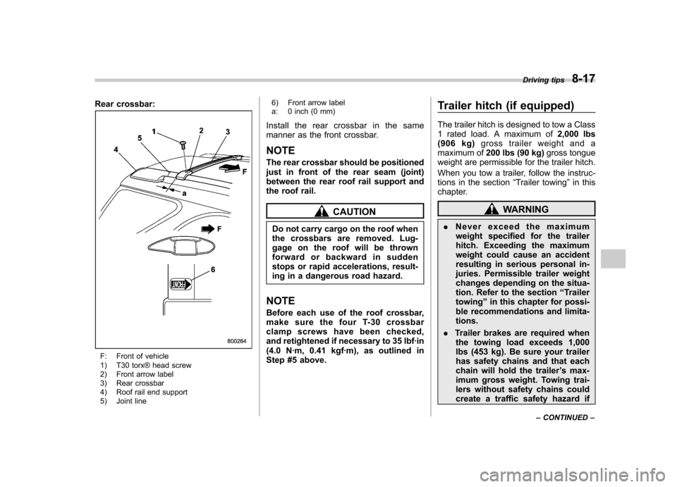
Rear crossbar:
F: Front of vehicle
1) T30 torx® head screw
2) Front arrow label
3) Rear crossbar
4) Roof rail end support
5) Joint line6) Front arrow label
a: 0 inch (0 mm)
Install the rear crossbar in the same
manner as the front crossbar. NOTE
The rear crossbar should be positioned
just in front of the rear seam (joint)
between the rear roof rail support and
the roof rail.
CAUTION
Do not carry cargo on the roof when
the crossbars are removed. Lug-
gage on the roof will be thrown
forward or backward in sudden
stops or rapid accelerations, result-
ing in a dangerous road hazard.
NOTE
Before each use of the roof crossbar,
make sure the four T-30 crossbar
clamp screws have been checked,
and retightened if necessary to 35 lbf·in
(4.0 N·m, 0.41 kgf·m), as outlined in
Step #5 above. Trailer hitch (if equipped)
The trailer hitch is designed to tow a Class
1 rated load. A maximum of
2,000 lbs
(906 kg) gross trailer weight and a
maximum of 200 lbs (90 kg) gross tongue
weight are permissible for the trailer hitch.
When you tow a trailer, follow the instruc-
tions in the section “Trailer towing ”in this
chapter.WARNING
. Never exceed the maximum
weight specified for the trailer
hitch. Exceeding the maximum
weight could cause an accident
resulting in serious personal in-
juries. Permissible trailer weight
changes depending on the situa-
tion. Refer to the section “Trailer
towing ”in this chapter for possi-
ble recommendations and limita-tions.
. Trailer brakes are required when
the towing load exceeds 1,000
lbs (453 kg). Be sure your trailer
has safety chains and that each
chain will hold the trailer ’s max-
imum gross weight. Towing trai-
lers without safety chains could
create a traffic safety hazard if Driving tips
8-17
– CONTINUED –
Page 255 of 364

If you park your vehicle in case of anemergency ........................................................ 9-2
Temporary spare tire ........................................... 9-2
Flat tires ............................................................... 9-4
Changing a flat tire .............................................. 9-4
Jump starting ...................................................... 9-8
How to jump start ................................................ 9-9
Engine overheating ............................................ 9-11
If steam is coming from the engine compartment .................................................... 9-11 If no steam is coming from the engine
compartment ................................................... 9-11
Towing ................................................................ 9-11
Towing and tie-down hooks. ............................... 9-12
Using a flat-bed truck. ........................................ 9-13
Towing with all wheels on the ground ................. 9-14
Rear gate –if the rear gate cannot be
unlocked .......................................................... 9-14
Moonroof –if the moonroof cannot be
closed .............................................................. 9-15
Maintenance tools ............................................. 9-16
Jack and jack handle ......................................... 9-16
In case of emergency
9
Page 269 of 364

3. Unlock the rear gate by pressing the
lever inside the trim to the left.
4. Open the rear gate from outside by
raising the rear gate handle.Moonroof
–if the moonroof
cannot be closed
If the moonroof cannot be closed with the
moonroof switch, you can close the moon-
roof manually.
1. Take out the hex-head wrench from
the glove compartment and screwdriver
from the tool bag.
2. Remove the map light lens by prying
the edge of the lens using a flat-head
screwdriver.
3. Remove the two screws that retain the
moonroof switch body. Then, remove the
moonroof switch.
4. Insert the wrench in the end of the
motor shaft.
To lower the moonroof, turn the wrench clockwise.
To close the moonroof, turn the wrench counterclockwise.
Have your vehicle checked and repaired
by an authorized SUBARU dealer. In case of emergency
9-15
Page 270 of 364

9-16In case of emergency
Maintenance tools
Your vehicle is equipped with the following
maintenance tools:
Wheel cover remover (only for vehicleswith wheel covers)
Screwdriver
Towing hook (eye bolt)
Wheel nut wrench
Hex-head wrench (only for vehicles with moonroof) &
Jack and jack handle
The jack is stored on the left side of the
trunk (Sedan) or cargo area (Wagon).
To take out the jack, turn the jackscrew
counterclockwise to loosen it, then re-
move the jack.
Sedan
1) Jack
2) Jack handle
3) Spare tire