Page 5 of 465
0-5
GENERAL INFORMATION
RODIUS 2006.09
0000-00
7) PART LOCATION ACCORDING TO PART NUMBER
Ex.) C 1 0 2 ▶
C : Symbol character for connector -
Symbol Character Description
C Connector (Connecting part that connects two wiring harness)
D Diode
G Ground
S Splice pack (Joint connector that connects various wiring harness)
1 : Part location number -
Part number according to locating section -
Part Numbe Location
□ 1□□Engine compartment
□ 2□□Instrument panel
□ 3□□Passenger compartment
□ 4□□Tailgate
□ 9□□Underbody
In the locating section, the assignment for part numbe
r
startsfrom left bottom and proceeds clockwise.
In the fuse and relay box or the instrument panel, the
partnumber is assigned from left top to light bottom. -
-
8) ELECTRIC SYMBOLS
Page 168 of 465
01-3
FUSE AND RELAY
RODIUS 2006.09
0000-00
8410-01FUSES AND RELAYS
1. OVERVIEW
The fuse and relay boxes are installed in the engine compartment and the left side of the
instrument panel. The capacity and designation labels of the fuses and relays are on the
covers.
This labels only describe the major functions and designations. Therefore, for detail, refer to the
circuit diagram.
2. LOCATION
Fuse and Relay in Engine Compartment
▶
The underhood fuse box is located in the engine compartment on the driver's side. You can find
the function, location and capacity for fuses and relays from the back plate of the fuse box
cover.
Page 169 of 465
01-4
RODIUS 2006.09
0000-00
FUSE AND RELAY
Fuse and Relay in Instrument Panel
▶
The fuse box is underneath the dash board on the driver's side. You can find the function,
location and capacity for fuses from the back plate of the fuse box cover. If any electrical device
doesn't operate, check for an open fuse. If any fuse is blown, replace it with a new fuse.
If a new fuse also opens, have the electrical system checked and repaired by Ssangyong
Dealer or Ssangyong Authorized Service Operation.
Page 215 of 465
0-3
CLUSTER
RODIUS 2006.09
8010-10
8010-01CLUSTER
1. APPEARANCE OF METER CLUSTER AND INDICATOR
DISPLAY
The instrument panel in this vehicle is different from conventional type of instrument panel. The
meter cluster and indicator display are separated. The meter cluster is located at the center o
f
the dash panel, and the indicator display is located in front of driver’s seat.
Meter cluster
Warning lamps and indicators
Page 257 of 465

0-8
RODIUS 2006.09
8790-04
PARKING AID SYSTEM
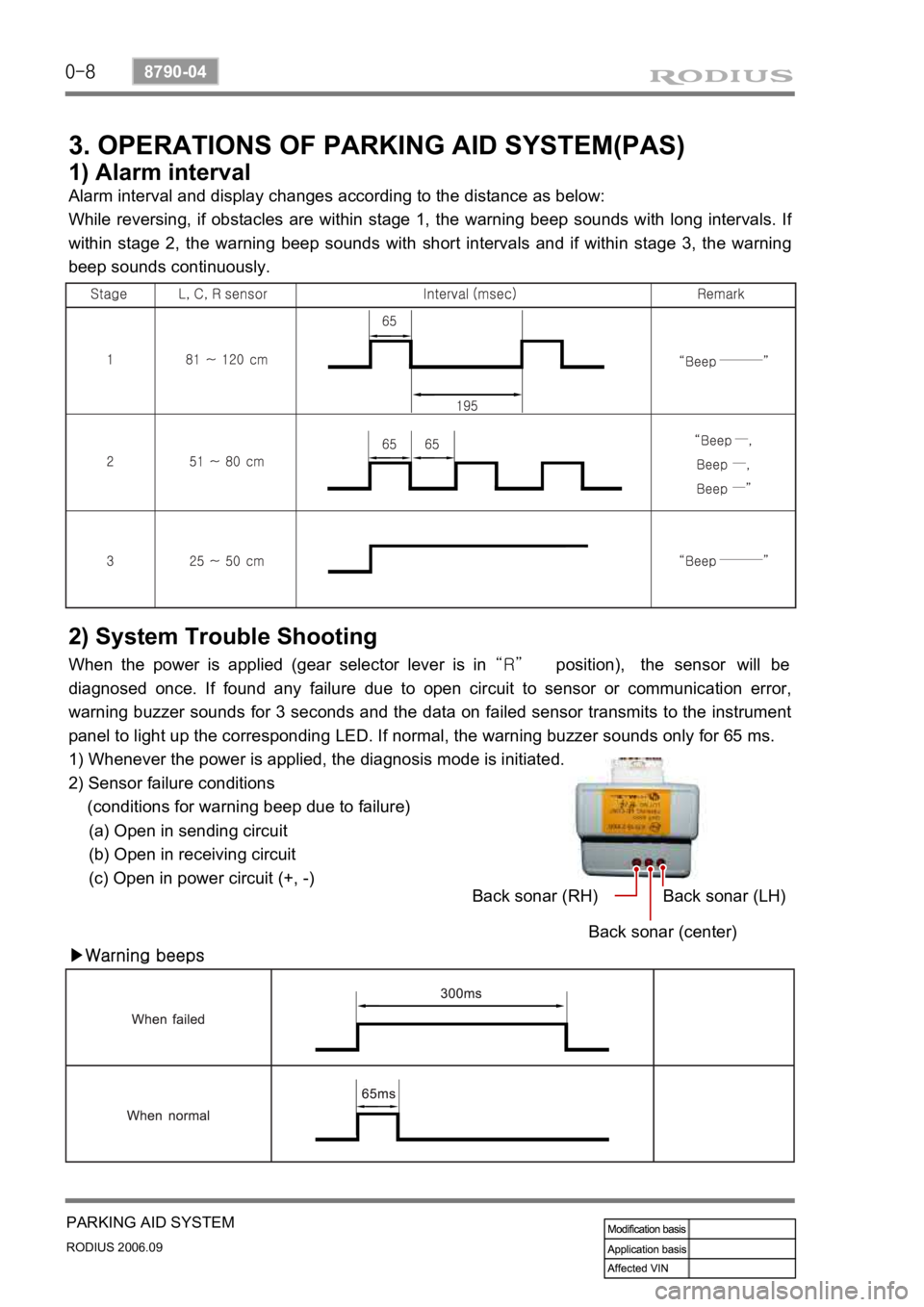
3. OPERATIONS OF PARKING AID SYSTEM(PAS)
1) Alarm interval
Alarm interval and display changes according to the distance as below:
While reversing, if obstacles are within stage 1, the warning beep sounds with long intervals. I
f
within stage 2, the warning beep sounds with short intervals and if within stage 3, the warning
beep sounds continuously.
2) System Trouble Shooting
When the power is applied (gear selector lever is in “R” position), the sensor will be
diagnosed once. If found any failure due to open circuit to sensor or communication error,
warning buzzer sounds for 3 seconds and the data on failed sensor transmits to the instrument
panel to light up the corresponding LED. If normal, the warning buzzer sounds only for 65 ms.
1) Whenever the power is applied, the diagnosis mode is initiated.
2) Sensor failure conditions
(conditions for warning beep due to failure)
(a) Open in sending circuit
(b) Open in receiving circuit
(c) Open in power circuit (+, -)
▶Warning beepsBack sonar (RH)
Back sonar (center)Back sonar (LH)
Page 273 of 465
0-4
RODIUS 2006.09
3410-01
TRANSFER CASE
1. PART TIME TRANSFER CASE OVERVIEW
By using the planetary gear sets, two-gears shift type part time transfer case achieves direct
connection when selecting 4WD “HIGH” and 2.48 of reduction gear ratio when selecting
4WD “LOW”.
The silent chain in transfer case transfers the output power to front wheels.
Simple operation of switches on instrument panel allows to shift to “2H”, “4H” and “4L”
easily while driving.
The warning lamp alarms the driver when the system is defective.
Page 285 of 465
0-16
RODIUS 2006.09
3410-01
TRANSFER CASE
This function is only available when the speed signal from speed sensor is about to stop
(below 2 km/h).
This function is only available when clutch pedal is depressed (manual transmission) o
r
selector lever is selected to “N” position (automatic transmission).
(TCCU must recognize the clutch pedal signal or “N” signal.)
Change the 4WD switch in instrument panel from 4H to 4L.
“4WD LOW” warning lamp in meter cluster blinks during this process, then remains
when the shift is completed.
“4WD CHECK” warning lamp comes on when the system is defective. -
-
-
-
- 4H → 4L ▶
Page 286 of 465
0-17
TRANSFER CASE
RODIUS 2006.09
3410-01
8. SYSTEM OPERATION
1) Transfer Case Control Unit (Tccu)
(1) 4WD Operation
TCCU is located under the front left seat and
permits the vehicle to shift from two-wheel
drive to four-wheel drive (and back shift)
according to drivers switch operation during
driving (For the shifting between 4WD HIGH
and 4WD LOW, stop the vehicle).
2H → 4H ▶
Change the 4WD switch in instrument panel from 2H to 4H.
This shift is available during driving.
“4WD HIGH” indicator in meter cluster comes on. -
-
-
When the system is defective
“4WD CHECK” warning lamp comes
on -
Change the 4WD switch in instrument panel from 4H to 2H.
This shift is available during driving.
“4WD HIGH” indicator in meter cluster goes out.
“4WD CHECK” warning lamp comes on when the system is defective. -
-
-
- 4H → 2H ▶