Page 334 of 465

0-14
RODIUS 2006.09
4892-01
ESP SYSTEM
(1) System Overview
When equipped with ABS, the braking force at each wheel will be controlled with 3-channel 4-
sensor method. And when equipped with ESP, 4 wheels will be controlled independently with 4-
channel method. (When controlling ABS system only, it will be operated with 3-channel
method.) When compared to the vehicle equipped with ABS/EBD only, the internal hydraulic
circuit has a normally-open separation valve and a shuttle valve in primary circuit and in
secondary circuit. When the vehicle brakes are not applied during engine running or when
applying the non-ABS operating brakes, the normally-open separation valve and the inlet valve
are open, whereas the normally-closed shuttle valve and the outlet valve are closed. When the
ESP system is operating, the normally-open separation valve will be closed by the solenoid
valve operation and the hydraulic circuit will be established by the shuttle valve. Then, the inlet
and outlet valves will be
closed or open depending on the braking pressure increase, decrease or unchanged
conditions.
<0d96007b008f008c0047009e00880099009500900095008e004700930088009400970047008a00960094008c009a004700960095004700880095008b0047009e00880099009500900095008e00470089008c008c00970047009a0096009c0095008b009a00
47009e008f008c00950047009b008f008c0047006c007a0077> is operating
▶Driving feeling when the ESP is operating
<0d96007500960090009a008c004700880095008b0047009d0090008900990088009b0090009600950047009b008f0088009b0047008b00990090009d008c00990047009a008c0095009a008c009a0047009e008f008c00950047009b008f008c0047006c00
7a007700470090009a004700960097008c00990088009b0090>ng When the ESP operates during vehicle movement, the ESP warning lamp on the instrument
panel flickers and beep comes on every 0.1 seconds. The ESP operation shows that the
vehicle stability is extremely unstable and it is used to warn the driver. The ESP system is just a
supplementary system for the vehicle motion and it cannot control the vehicle when it exceeds
the physical limits. Do not solely rely on the system but be advised to drive the vehicle safely.
When the ESP system activates, the driving feeling can be different depending on vehicle
driving conditions. For example, you will feel differently when the ESP system is activated
during when ABS is operating with the brakes applied and when brakes are not applied on a
curve. Thus, the ESP system would make the driver feel more abruptly when the brakes are
applied during the ESP system activation.
The ESP system may transfer noise and vibration to the driver due to the pressure changes
caused by the motor and valve operations in a very short period of time. Extreme cornering will
trigger the ESP operation and this will make the driver feel noise and vibration due to sudden
brake application. Also, the ESP system controls the engine output. So, the driver may notice
the engine output decrease even when the accelerator pedal is being applied.
Page 376 of 465
0-4
RODIUS 2006.09
6810-20
AIR CONDITIONING SYSTEM
2. SYSTEM LAYOUT AND COMPONENTS
Front air conditioner module assembly - inside instrument panel
Page 385 of 465

0-13
AIR CONDITIONING SYSTEM
RODIUS 2006.09
6810-20
4. SENSORS AND ACTUATORS
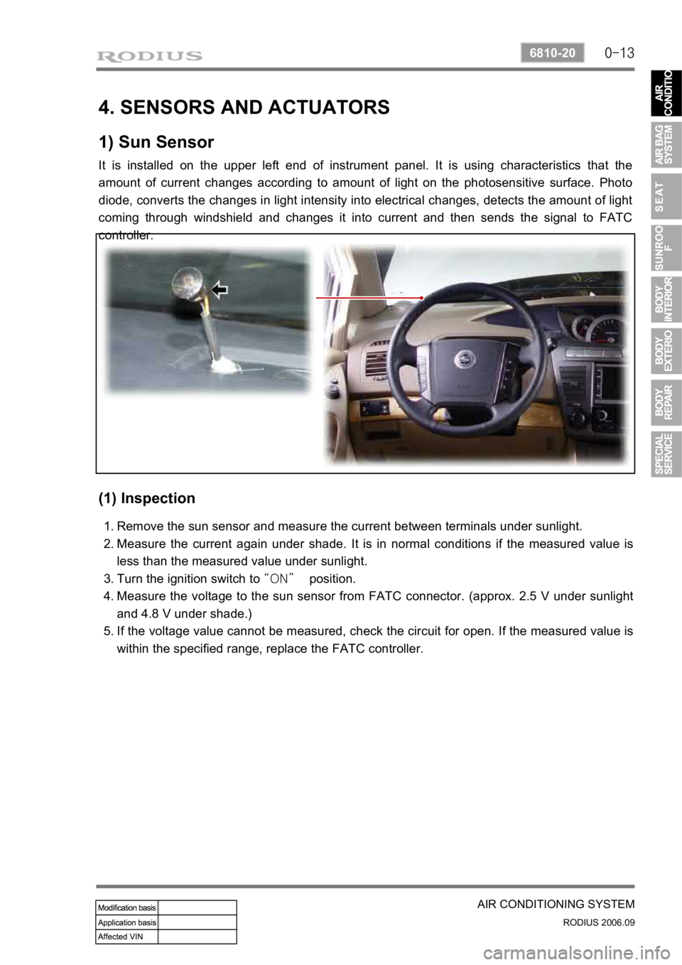
1) Sun Sensor
It is installed on the upper left end of instrument panel. It is using characteristics that the
amount of current changes according to amount of light on the photosensitive surface. Photo
diode, converts the changes in light intensity into electrical changes, detects the amount of light
coming through windshield and changes it into current and then sends the signal to FATC
controller.
(1) Inspection
Remove the sun sensor and measure the current between terminals under sunlight.
Measure the current again under shade. It is in normal conditions if the measured value is
less than the measured value under sunlight.
Turn the ignition switch to “ON” position.
Measure the voltage to the sun sensor from FATC connector. (approx. 2.5 V under sunlight
and 4.8 V under shade.)
If the voltage value cannot be measured, check the circuit for open. If the measured value is
within the specified range, replace the FATC controller. 1.
2.
3.
4.
5.
Page 386 of 465
0-14
RODIUS 2006.09
6810-20
AIR CONDITIONING SYSTEM
2) Active Incar/Humidity Sensor (AIH Sensor)
The AIH sensor is installed at the driver side instrument panel undercover. It is a sensor that
detects interior temperature and humidity.
(1) Location
(2) Functions
Interior temperature sensor
▶
This sensor is a negative temperature coefficient (NTC) thermistor and detects the interio
r
temperature with air coming from senor hole and then sends the voltage value according to the
changed resistance to FATC controller.
Humidity sensor
▶
This sensor detects the interior humidity with humidity cell and then sends the voltage value
according to the changed humidity to FATC controller.
Humidity
sensor
Active incar sensor
(interior temperature
sensor)
Page 406 of 465

0-6
RODIUS 2006.09
8810-01
AIR BAG SYSTEM
3. AIRBAG FUNCTION DESCRIPTION
1) Bag (Cushion)
The airbag system performance is influenced on the cushion size, shape and position.
The cushion strength is a important parameter on the impact absorb effect.
Therefore, the control of the airbag performance depends on cushion size, shape, inflato
r
characteristic and vent hole size for the gas discharge.
The cushion’s material and folding function to control the cushion deployment
direction and the performance to protect passenger’s face. ·
·
·
·
2) Airbag Module
The driver airbag module is under the center pad of the steering wheel.
The passenger airbag module is installed in the instrument panel at passenger side.
The driver and passenger side airbag is inside each seat.
3) Module Cover/Housing
It is a type of a container that includes the cushion and the inflator.
The module housing functions to deliver the reaction force between the body structure and
the airbag (The airbag reaction is absorbed generally to the steering wheel or instrument
panel).
The module cover must be considered in a viewpoint of protection between exterior,
internal units and cushion. Also the module cover should be designed not to cause any
personal injury for deployment. ·
·
·
Do not disassemble the airbag module because unintentional deployment of the airbags
resulting from any damage or interference of the module can cause injury. -