Page 346 of 465
0-7
ABS SYSTEM
RODIUS 2006.09
4892-01
Kamm circle ▶
Before we go into the Kamm circle, you
should know that a tire offers a maximum o
f
100 % transmissibility. It is all the same fo
r
the tire whether we require 100 % in the
direction of braking or in the direction of the
acting lateral force, e.g. when driving round
curves. If we drive into a curve too fast and
the tire requires 100 % transmissibility as
cornering force, the tire cannot transmit any
additional brake force. In spite of the ABS
the car is carried out of the curve. The
relationship between brake force B and
cornering force S is shown very clearly in
the Kamm circle. If we put a vehicle wheel in
this circle, the relationship becomes even
clearer. In this relationship: as long as the
acting forces and the resulting force remain
within the circle, the vehicle is stable to
drive. If a force exceeds the circle, the
vehicle leaves the road.
Page 347 of 465
0-8
RODIUS 2006.09
4892-01
ABS SYSTEM
Brake force
When depressing the brake pedal the
brake force increases to the maximum,
then the brake force decreases until the
wheel locks.
Cornering force
The cornering force is a maximum when
the wheel is turning freely with zero slip.
When braking the cornering force falls to
zero if the wheel locks (slip 100 %).
ABS operating range
The operating range starts just before the
maximum brake force and ends in
maximum, for the unstable range then
begins, in which no further modulation is
possible. The ABS controls the regulation
of the brake pressure so that the brake
force only becomes great enough for a
sufficient proportion of cornering force to
remain. With ABS we remain in the
Kamm circle as long as the car is driving
sensibly. We will leave driving physics
with these statements and turn to the
braking systems with and without ABS. -
-
- Brake and cornering force ▶
Page 348 of 465

0-9
ABS SYSTEM
RODIUS 2006.09
4892-01
(3) Basic ABS Controls
Applications of the ABS control unit
The signals produced by the wheel sensors
are evaluated in the electronic control unit.
From the information received, the control
unit must first compute the following
variables:
- Wheel speed
- Reference speed
- Deceleration
- Slip
Reference speed ▶
The reference speed is the mean, I.e. average speed of all wheel speeds determined by simple
approximation.
Simplified ABS control ▶
If, during braking, one wheel speed deviates from the reference speed, the ABS control unit
attempts to correct that wheel speed by modulating the brake pressure until it again matches
the reference speed. When all four wheels tend to lock, all four wheels speeds suddenly
deviate from the previously determined reference speed. In that case, the control cycle is
initiated again in order to again correct the wheel speed by modulating the brake pressure.
Selector low control ▶
This control is used for regulating the brake pressure for rear axle during ABS operation. This
control uses lower adhesion coefficient to prevent the rear wheels from locking.
Page 351 of 465
0-12
RODIUS 2006.09
4892-01
ABS SYSTEM
1. COMPONENTS AND LOCATION
Newly introduced ABS has a different shape of integrated hydraulic modulator and HECU
(Hydraulic and Electronic Control Unit) compared to existing ABS. And, the wheel speed senso
r
uses different method to detect wheel speed. The basic function of the ABS that maintains the
vehicle stability by controlling the steerability of the vehicle when braking has not been
changed.
Page 354 of 465

0-15
ABS SYSTEM
RODIUS 2006.09
4892-01
3. ABS SYSTEM DESCRIPTION
1) EBD (ELECTRONIC BRAKE FORCE DISTRIBUTION) SYSTEM
(1) System Description
As an add-on logic to the ABS base algorithm, EBD works in a range in which the intervention
thresholds for ABS control can not be reached. EBD ensures that the rear wheels are
sensitively monitored for slip with respect to the front axle. If slip is detected, the inlet valves fo
r
the rear wheels are switched to pressure hold to prevent a further increase in pressure at the
rear-wheel breaks, thus electronically reproducing a pressure-reduction function at the rear-
wheel brakes. ABS features an enhanced algorithm which includes control of the brake force
distribution between the front and rear axles. This is called Electronic Brake Distribution. In an
unloading car condition the brake efficiency is comparable to the conventional system but for a
fully loaden vehicle the efficiency of the EBD system is higher due to the better use of rear axle
braking capability.
(2) The Benefits of EBD
Elimination of conventional proportioning valve EBD utilizes the existing rear axle wheel
speed sensor to monitor rear wheel slip.
Based on many variables in algorithm a pressure hold, increase and/or decrease pulsetrain
may be triggered at the rear wheels insuring vehicle stability.
Vehicle approaches the ideal brake force distribution (front to rear).
Constant brake force distribution during vehicle lifetime.
EBD function is monitored via ABS safety logic (conventional proportioning valves are not
monitorable).
“Keep alive” function. -
-
-
-
-
-
Page 355 of 465

0-16
RODIUS 2006.09
4892-01
ABS SYSTEM
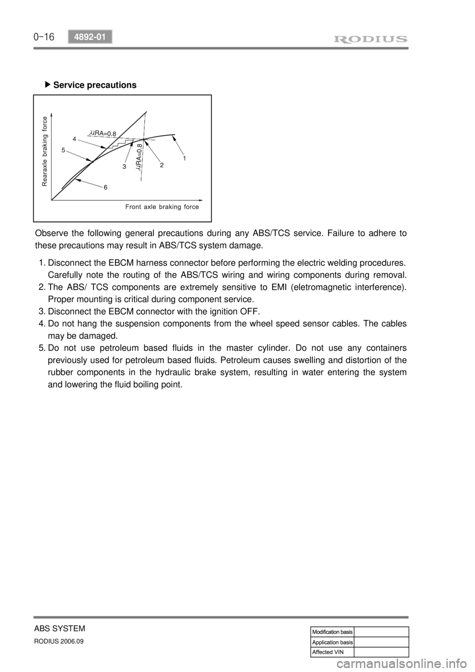
Service precautions ▶
Observe the following general precautions during any ABS/TCS service. Failure to adhere to
these precautions may result in ABS/TCS system damage.
Disconnect the EBCM harness connector before performing the electric welding procedures.
Carefully note the routing of the ABS/TCS wiring and wiring components during removal.
The ABS/ TCS components are extremely sensitive to EMI (eletromagnetic interference).
Proper mounting is critical during component service.
Disconnect the EBCM connector with the ignition OFF.
Do not hang the suspension components from the wheel speed sensor cables. The cables
may be damaged.
Do not use petroleum based fluids in the master cylinder. Do not use any containers
previously used for petroleum based fluids. Petroleum causes swelling and distortion of the
rubber components in the hydraulic brake system, resulting in water entering the system
and lowering the fluid boiling point. 1.
2.
3.
4.
5.
Page 357 of 465
0-18
RODIUS 2006.09
4892-01
ABS SYSTEM
2) HYDRAULIC CIRCUIT DIAGRAM
(1) Hydraulic Circuit of ABS
The vehicle equipped only with the ABS controls the wheel’s braking force using three 3-
channel 4-sensor method. The front wheels that are the primary circuit of the brake system is
composed of two wheel speed sensors and two channel valves system with two inlet valves
and two outlet valves. The rear wheels that are the secondary circuit of the brake system is
composed of two wheel speed sensors, one inlet valve and one outlet valve. This system is
similar to the one from the previous model.
Page 358 of 465
0-19
ABS SYSTEM
RODIUS 2006.09
4892-01
(2) ABS Circuit Per ABS Operation Range
Hydraulic Pressure Circuit when ABS is Not Operating ▶
No Hydraulic Pressure Circuit when ABS is Operating ▶
The hydraulic pressure in the master cylinder increases through the vacuum booster and it is
delivered to the wheel via the normal open inlet valve. At this moment, the normally-closed
outlet valve is closed. The speed of the wheel that hydraulic pressure is delivered reduces
gradually
As hydraulic pressure on each wheel increases, the wheel tends to lock. In order to prevent the
wheel from locking, the hydraulic valve modulator operates the inlet valve control solenoid to
close the inlet valve and stop the hydraulic pressure increases. At this moment, the outlet valve
is closed. This procedure helps the wheel to maintain a stable hydraulic pressure.