Page 73 of 465

06-4
RODIUS 2006.09
0000-00
LUBRICATION SYSTEM
NO. FUNCTION NO. FUNCTION
1 Oil pump 18 Oil supply (to exhaust camshaft)
2 Oil gallery (to oil filter) 19 Oil supply (to intake camshaft)
3 Oil filter 20Oil supply
(to exhaust camshaft bearing)
4 Oil pressure switch 21Oil supply
(to intake camshaft bearing)
5 Main oil gallery 22Oil gallery
(oil supply to exhaust valve tappet)
6 Cylinder head closing cover 23Oil gallery
(oil supply to intake valve tappet)
7 Oil gallery (at chain tensioner) 24 Camshaft closing cover
8 Oil non-return valve 25Ball (φ 8 mm)
9 Chain tensioner 26 Screw plug
10 Vent (chain tensioner) 27 Camshaft adjuster
11Front closing cover (φ 17 mm)28Front closing cover
(intake camshaft)
12Oil gallery
(perpendicular to the shaft)29Front treaded bushing
(exhaust camshaft)
13Ball (φ 6 mm)30 Valve tappet
14 Oil spray nozzle (timing chain) aOil gallery
(from oil pump to oil filter)
15 Oil gallery (at cylinder head) b Main oil gallery
16Ball (φ 15mm)cOil return line
(oil returns to the oil pan when
replacing the filter element)
17Oil restriction inner (φ 4mm)
OIL CIRCULATION ▶
Page 83 of 465

08-6
RODIUS 2006.09
0000-00
ENGINE ELECTRIC DEVICES
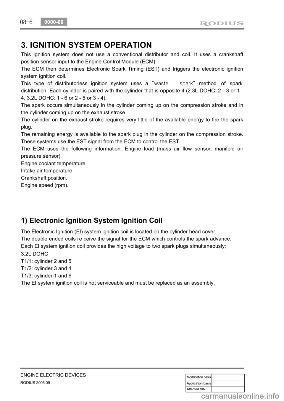
3. IGNITION SYSTEM OPERATION
This ignition system does not use a conventional distributor and coil. It uses a crankshaft
position sensor input to the Engine Control Module (ECM).
The ECM then determines Electronic Spark Timing (EST) and triggers the electronic ignition
system ignition coil.
This type of distributorless ignition system uses a “waste spark” method of spark
distribution. Each cylinder is paired with the cylinder that is opposite it (2.3L DOHC: 2 - 3 or 1 -
4, 3.2L DOHC: 1 - 6 or 2 - 5 or 3 - 4).
The spark occurs simultaneously in the cylinder coming up on the compression stroke and in
the cylinder coming up on the exhaust stroke.
The cylinder on the exhaust stroke requires very little of the available energy to fire the spark
plug.
The remaining energy is available to the spark plug in the cylinder on the compression stroke.
These systems use the EST signal from the ECM to control the EST.
The ECM uses the following information: Engine load (mass air flow sensor, manifold ai
r
pressure sensor).
Engine coolant temperature.
Intake air temperature.
Crankshaft position.
Engine speed (rpm).
1) Electronic Ignition System Ignition Coil
The Electronic Ignition (EI) system ignition coil is located on the cylinder head cover.
The double ended coils re ceive the signal for the ECM which controls the spark advance.
Each EI system ignition coil provides the high voltage to two spark plugs simultaneously;
3.2L DOHC
T1/1: cylinder 2 and 5
T1/2: cylinder 3 and 4
T1/3: cylinder 1 and 6
The EI system ignition coil is not serviceable and must be replaced as an assembly.
Page 106 of 465
0-10
RODIUS 2006.09
0000-00
ENGINE GENERAL
2) D27DTP (Power Up) Engine Performance Curve
(1) Output and Torque: vehicle with automatic transmission
Oil Temperature/Pressure and Boost Pressure: vehicle with automatic
transmission (2)
Page 107 of 465
0-11
ENGINE GENERAL
RODIUS 2006.09
0000-00
3) D27DT Engine Performance Curve
(1) Output and Torque
(2) Oil Temperature/Pressure and Boost Pressure
Page 216 of 465
0-4
RODIUS 2006.09
8010-10
CLUSTER
2. DESCRIPTIONS OF INDICATOR DISPLAY
1. Immobilizer indicator
2. Glow indicator
3. Winter mode indicator
4. Left turn signal indicator
5. Auto shift indicator (for automatic transmission)
6. Right turn signal indicator
7. Harzard indicator*
8. Engine check warning light
9. Cruise control indicator*
10. 4WD CHECK warning light
11. 4WD HIGH indicator
12. 4WD LOW indicator
13. Brake warning light14. Battery charge warning light
15. Seat belt reminder
16. Low fuel level warning light
17. Heated glass indicator
18. Door open warning light
19. High beam indicator
20. Engine oil pressure warning light
21. Air bag warning light
22. Water separator warning light
23. ABS warning light
24. EBD warning light
25. ESP warning light
Page 321 of 465

0-7
BRAKS SYSTEM
RODIUS 2006.09
4830-01
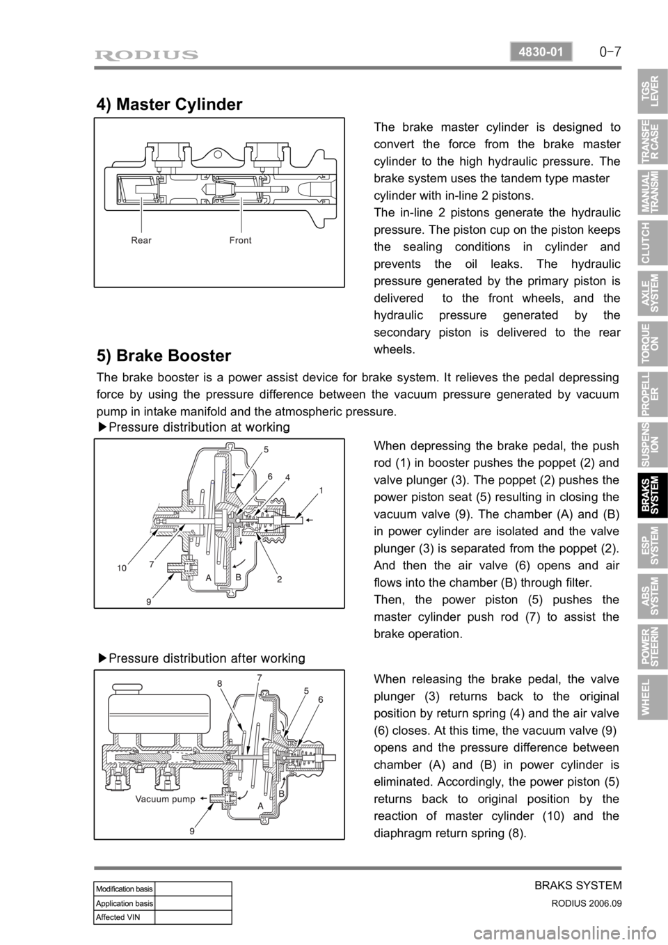
4) Master Cylinder
The brake master cylinder is designed to
convert the force from the brake maste
r
cylinder to the high hydraulic pressure. The
brake system uses the tandem type master
cylinder with in-line 2 pistons.
The in-line 2 pistons generate the hydraulic
pressure. The piston cup on the piston keeps
the sealing conditions in cylinder and
prevents the oil leaks. The hydraulic
pressure generated by the primary piston is
delivered to the front wheels, and the
hydraulic pressure generated by the
secondary piston is delivered to the rea
r
wheels.
5) Brake Booster
The brake booster is a power assist device for brake system. It relieves the pedal depressing
force by using the pressure difference between the vacuum pressure generated by vacuum
pump in intake manifold and the atmospheric pressure.
▶Pressure distribution at working
When depressing the brake pedal, the push
rod (1) in booster pushes the poppet (2) and
valve plunger (3). The poppet (2) pushes the
power piston seat (5) resulting in closing the
vacuum valve (9). The chamber (A) and (B)
in power cylinder are isolated and the valve
plunger (3) is separated from the poppet (2).
And then the air valve (6) opens and ai
r
flows into the chamber (B) through filter.
Then, the power piston (5) pushes the
master cylinder push rod (7) to assist the
brake operation.
▶Pressure distribution after working
When releasing the brake pedal, the valve
plunger (3) returns back to the original
position by return spring (4) and the air valve
(6) closes. At this time, the vacuum valve (9)
opens and the pressure difference between
chamber (A) and (B) in power cylinder is
eliminated. Accordingly, the power piston (5)
returns back to original position by the
reaction of master cylinder (10) and the
diaphragm return spring (8).
Page 322 of 465
0-8
RODIUS 2006.09
4830-01
BRAKS SYSTEM
6) Master Cylider & Booster
ABS system is basically equipped to STAVIC.
Vehicle which adapted ESP system in option has two pressure sensors under master cylinder
and these two sensor are used for BAS (Brake Assist System) system.
Do not disassemble the brake oil pressure sensors These can not be reinstalled of
disassembled.
After reinstall the reserver tank perform a air bleeding of brake system
-
-
Vehicle with ESP Vehicle with ABS
Brake fluid reservoir tank Master cylinder
Page 336 of 465
0-16
RODIUS 2006.09
4892-01
ESP SYSTEM
▶When applied ABS (decreased pressure)
The pressure decreases just before the wheel speed drops and the wheels. The inlet valve
closes and the outlet valve opens as in the ABS HECU and the oil is gathered at the low
pressure chamber while no additional oil is being supplied.
Then the pump operates to allow fast oil drainage.