Page 334 of 465

0-14
RODIUS 2006.09
4892-01
ESP SYSTEM
(1) System Overview
When equipped with ABS, the braking force at each wheel will be controlled with 3-channel 4-
sensor method. And when equipped with ESP, 4 wheels will be controlled independently with 4-
channel method. (When controlling ABS system only, it will be operated with 3-channel
method.) When compared to the vehicle equipped with ABS/EBD only, the internal hydraulic
circuit has a normally-open separation valve and a shuttle valve in primary circuit and in
secondary circuit. When the vehicle brakes are not applied during engine running or when
applying the non-ABS operating brakes, the normally-open separation valve and the inlet valve
are open, whereas the normally-closed shuttle valve and the outlet valve are closed. When the
ESP system is operating, the normally-open separation valve will be closed by the solenoid
valve operation and the hydraulic circuit will be established by the shuttle valve. Then, the inlet
and outlet valves will be
closed or open depending on the braking pressure increase, decrease or unchanged
conditions.
<0d96007b008f008c0047009e00880099009500900095008e004700930088009400970047008a00960094008c009a004700960095004700880095008b0047009e00880099009500900095008e00470089008c008c00970047009a0096009c0095008b009a00
47009e008f008c00950047009b008f008c0047006c007a0077> is operating
▶Driving feeling when the ESP is operating
<0d96007500960090009a008c004700880095008b0047009d0090008900990088009b0090009600950047009b008f0088009b0047008b00990090009d008c00990047009a008c0095009a008c009a0047009e008f008c00950047009b008f008c0047006c00
7a007700470090009a004700960097008c00990088009b0090>ng When the ESP operates during vehicle movement, the ESP warning lamp on the instrument
panel flickers and beep comes on every 0.1 seconds. The ESP operation shows that the
vehicle stability is extremely unstable and it is used to warn the driver. The ESP system is just a
supplementary system for the vehicle motion and it cannot control the vehicle when it exceeds
the physical limits. Do not solely rely on the system but be advised to drive the vehicle safely.
When the ESP system activates, the driving feeling can be different depending on vehicle
driving conditions. For example, you will feel differently when the ESP system is activated
during when ABS is operating with the brakes applied and when brakes are not applied on a
curve. Thus, the ESP system would make the driver feel more abruptly when the brakes are
applied during the ESP system activation.
The ESP system may transfer noise and vibration to the driver due to the pressure changes
caused by the motor and valve operations in a very short period of time. Extreme cornering will
trigger the ESP operation and this will make the driver feel noise and vibration due to sudden
brake application. Also, the ESP system controls the engine output. So, the driver may notice
the engine output decrease even when the accelerator pedal is being applied.
Page 339 of 465
0-19
ESP SYSTEM
RODIUS 2006.09
4892-01
▶Hydraulic Diagram of HBA
The above figure shows one front and one rear wheel and the same hydraulic circuit forms as
in the ESP operation.
When HECU recognizes that it is an emergency and it is required for hard braking, depending
on the pressure value of the brake pressure sensor and pressure changes caused by the
pressure sensor timing, it operates the pump immediately to apply the brake pressure at the
wheels.
Then, the pressure in the pump increases until just before the corresponding wheel gets locked.
The motor still keeps rotating and the outlet valve and the separation valve are will stay closed.
When the wheel starts to lock, the HBA function cancels and switches to ABS operation.
Page 348 of 465

0-9
ABS SYSTEM
RODIUS 2006.09
4892-01
(3) Basic ABS Controls
Applications of the ABS control unit
The signals produced by the wheel sensors
are evaluated in the electronic control unit.
From the information received, the control
unit must first compute the following
variables:
- Wheel speed
- Reference speed
- Deceleration
- Slip
Reference speed ▶
The reference speed is the mean, I.e. average speed of all wheel speeds determined by simple
approximation.
Simplified ABS control ▶
If, during braking, one wheel speed deviates from the reference speed, the ABS control unit
attempts to correct that wheel speed by modulating the brake pressure until it again matches
the reference speed. When all four wheels tend to lock, all four wheels speeds suddenly
deviate from the previously determined reference speed. In that case, the control cycle is
initiated again in order to again correct the wheel speed by modulating the brake pressure.
Selector low control ▶
This control is used for regulating the brake pressure for rear axle during ABS operation. This
control uses lower adhesion coefficient to prevent the rear wheels from locking.
Page 354 of 465

0-15
ABS SYSTEM
RODIUS 2006.09
4892-01
3. ABS SYSTEM DESCRIPTION
1) EBD (ELECTRONIC BRAKE FORCE DISTRIBUTION) SYSTEM
(1) System Description
As an add-on logic to the ABS base algorithm, EBD works in a range in which the intervention
thresholds for ABS control can not be reached. EBD ensures that the rear wheels are
sensitively monitored for slip with respect to the front axle. If slip is detected, the inlet valves fo
r
the rear wheels are switched to pressure hold to prevent a further increase in pressure at the
rear-wheel breaks, thus electronically reproducing a pressure-reduction function at the rear-
wheel brakes. ABS features an enhanced algorithm which includes control of the brake force
distribution between the front and rear axles. This is called Electronic Brake Distribution. In an
unloading car condition the brake efficiency is comparable to the conventional system but for a
fully loaden vehicle the efficiency of the EBD system is higher due to the better use of rear axle
braking capability.
(2) The Benefits of EBD
Elimination of conventional proportioning valve EBD utilizes the existing rear axle wheel
speed sensor to monitor rear wheel slip.
Based on many variables in algorithm a pressure hold, increase and/or decrease pulsetrain
may be triggered at the rear wheels insuring vehicle stability.
Vehicle approaches the ideal brake force distribution (front to rear).
Constant brake force distribution during vehicle lifetime.
EBD function is monitored via ABS safety logic (conventional proportioning valves are not
monitorable).
“Keep alive” function. -
-
-
-
-
-
Page 355 of 465

0-16
RODIUS 2006.09
4892-01
ABS SYSTEM
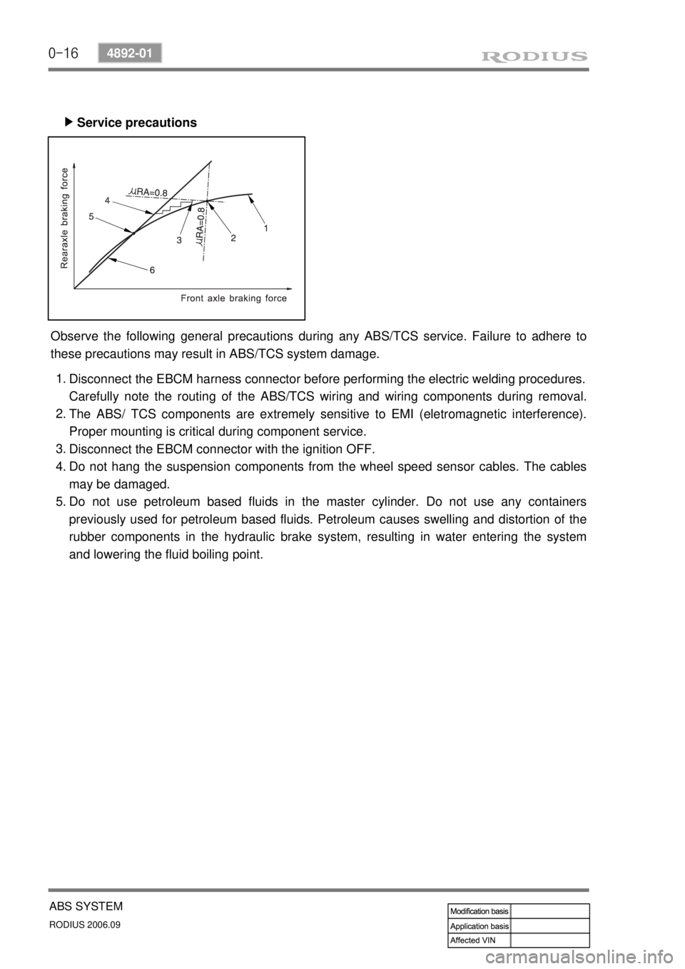
Service precautions ▶
Observe the following general precautions during any ABS/TCS service. Failure to adhere to
these precautions may result in ABS/TCS system damage.
Disconnect the EBCM harness connector before performing the electric welding procedures.
Carefully note the routing of the ABS/TCS wiring and wiring components during removal.
The ABS/ TCS components are extremely sensitive to EMI (eletromagnetic interference).
Proper mounting is critical during component service.
Disconnect the EBCM connector with the ignition OFF.
Do not hang the suspension components from the wheel speed sensor cables. The cables
may be damaged.
Do not use petroleum based fluids in the master cylinder. Do not use any containers
previously used for petroleum based fluids. Petroleum causes swelling and distortion of the
rubber components in the hydraulic brake system, resulting in water entering the system
and lowering the fluid boiling point. 1.
2.
3.
4.
5.
Page 357 of 465
0-18
RODIUS 2006.09
4892-01
ABS SYSTEM
2) HYDRAULIC CIRCUIT DIAGRAM
(1) Hydraulic Circuit of ABS
The vehicle equipped only with the ABS controls the wheel’s braking force using three 3-
channel 4-sensor method. The front wheels that are the primary circuit of the brake system is
composed of two wheel speed sensors and two channel valves system with two inlet valves
and two outlet valves. The rear wheels that are the secondary circuit of the brake system is
composed of two wheel speed sensors, one inlet valve and one outlet valve. This system is
similar to the one from the previous model.
Page 361 of 465
0-22
RODIUS 2006.09
4892-01
ABS SYSTEM
Pumping
▶
ECU (Including Solenoid Valves ? ESP Equipped Model)
▶
ECU lower cover)
▶
When the cam pushes the left plunger
during motor operation, the system pressure
is generated in the left cylinder. At this time,
the right plunger is expanded by spring force
and the expanded volume of the right
cylinder draws the brake fluid.
HECU controls the hydraulic valves by
supplying or cutting off the voltage to
solenoid valves depending on the wheel
speed and other information from wheel
speed sensors.
The figure shown in left side is for ESP
ECU. There are two channels for front
wheels and one channel for rear wheels.
Each channel has one inlet and one outlet
valve, therefore,
there are six solenoid valves.
The electrical components are weak to
moisture. To protect ECU, GoreTex-based
plate is used at ECU lower cover. The vent
hall (arrow) allows air to ventilate but does
not allow moisture to penetrate.