2007 Seat Ibiza 5D maintenance
[x] Cancel search: maintenancePage 201 of 272

Checking and refilling levels199
Safety First
Operating instructions
Tips and Maintenance
Te c h n i c a l D a t a
easier to choose the correct tyres. Radial tyres have the tyre designations
marked on the sidewall, for example:
195/65 R15 91T
This contains the following information:
195 Tyre width in mm
65 Height/width ratio in %
R Tyre construction: Radial
15 Rim diameter in inches
91 Load rating code
T Speed rating
The tyres could also have the following information:
•
A direction of rotation symbol
•
“Reinforced” denotes heavy-duty tyres.
The manufacturing date is also indicated on the tyre sidewall (possibly only
on the inner side of the wheel).
“DOT... 1103...” means, for example, that the tyre was produced in the 11th
week of 2003.
We recommend that work on tyres and wheels is carried out by an Authorised
Service Centre. They are familiar with the procedure and have the necessary
special tools and spare parts as well as the proper facilities for disposing of
the old tyres.
Any Authorised Service Centre has full information on the technical require-
ments when installing or changing tyres, wheels or wheel trims.
WARNING
•
We recommend that you use only wheels and tyres which have been
approved by SEAT for your model. Fa ilure to do so could impair vehicle
handling. Risk of accident.
•
Avoid running the vehicle on tyres th at are more than six years old. If
you have no alternative, you should dr ive slowly and with extra care at all
times.
•
Never use old tyres or those with an unknown “history of use”.
•
If wheel trims are retrofitted, you must ensure that the flow of air to the
brakes is not restricted. This could cause them to overheat.
•
All four wheels must be fitted with radial tyres of the same type, size
(rolling circumference) and the same tread pattern.For the sake of the environment
Old tyres must be disposed of accordi ng to the laws in the country concerned.
Note
•
For technical reasons, it is not generally possible to use the wheels from
other vehicles. This can also apply to wheels of the same model. The use of
wheels or tyres which have not been approved by SEAT for use with your
model may invalidate the vehicle's type approval for use on public roads.
•
If the spare tyre is not the same as the tyres that are mounted on the
vehicle - for example with winter tyres - you should only use the spare tyre for
a short period of time and drive with extra care. Refit the normal road wheel
as soon as possible.
Wheel bolts
Wheel bolts must be tightened to the correct torque.The design of wheel bolts is matched to the rims. If different wheel rims are
fitted, the correct wheel bolts with the right length and correctly shaped bolt
WARNING (continued)
IBI_ANG_0707 Seite 199 Montag, 6. August 2007 3:59 15
Page 203 of 272

Checking and refilling levels201
Safety First
Operating instructions
Tips and Maintenance
Te c h n i c a l D a t a
Note
•
The rims of the IBIZA CUPRA have been designed so as not to obstruct the
optional 4-cylinder brake unit.
•
The CUPRA version has a specific tyre for driving in winter of 205/40 17 XL
84H. When you use this winter tyre, do not exceed 210 km/h.
Snow chainsSnow chains are only permitted on the front wheels and only for tyres 155/80
R13; 165/70 R14 and 185/80 R14. Snow ch ains must have fine-pitch links
which do not protrude more than 15 mm, including tension device.
Remaining tyres can be fitted with chains no thicker than 9 mm.
Remove wheel hub covers and trim rings before fitting snow chains. For safety
reasons cover caps, available in any Authorised Service Centre, must then be
fitted over the wheel bolts.
WARNING
Observe the fitting instructions provided by the snow chain manufacturer.
Caution
You must remove the snow chains to drive on roads which are free of snow.
Otherwise they will impair handling, damage the tyres and wear out very
quickly.
Note
In some countries, the speed limit for using snow chains is 50 km/h. The legal
requirements of the country should be followed.
IBI_ANG_0707 Seite 201 Montag, 6. August 2007 3:59 15
Page 205 of 272

If and when203
Safety First
Operating instructions
Tips and Maintenance
Te c h n i c a l D a t a
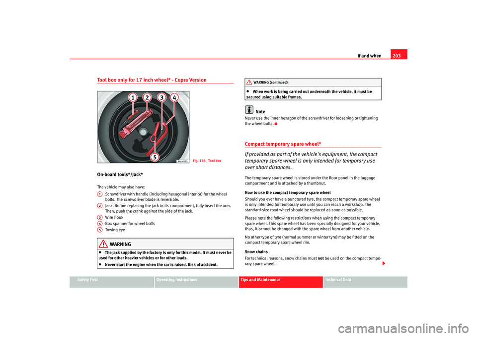
Tool box only for 17 inch wheel* - Cupra VersionOn-board tools*/Jack*The vehicle may also have:
Screwdriver with handle (including hexagonal interior) for the wheel
bolts. The screwdriver blade is reversible.
Jack. Before replacing the jack in it s compartment, fully insert the arm.
Then, push the crank against the side of the jack.
Wire hook
Box spanner for wheel bolts
Towing eye
WARNING
•
The jack supplied by the factory is only for this model. It must never be
used for other heavier vehicles or for other loads.
•
Never start the engine when the car is raised. Risk of accident.
•
When work is being carried out underneath the vehicle, it must be
secured using suitable frames.Note
Never use the inner hexagon of the sc rewdriver for loosening or tightening
the wheel bolts.Compact temporary spare wheel*
If provided as part of the vehicle's equipment, the compact
temporary spare wheel is only intended for temporary use
over short distances.The temporary spare wheel is stored under the floor panel in the luggage
compartment and is attached by a thumbnut.
How to use the compact temporary spare wheel
Should you ever have a punctured tyre, the compact temporary spare wheel
is only intended for temporary use until you can reach a workshop. The
standard-size road wheel should be replaced as soon as possible.
Please note the following restrictions when using the compact temporary
spare wheel. This spare wheel has been specially designed for your vehicle,
thus, it cannot be changed with the spare wheel from another vehicle.
No other type of tyre (normal summer or winter tyre) may be fitted on the
compact temporary spare wheel rim.
Snow chains
For technical reasons, snow chains must not be used on the compact tempo-
rary spare wheel.
Fig. 136 Tool box
A1A2A3A4A5
WARNING (continued)
IBI_ANG_0707 Seite 203 Montag, 6. August 2007 3:59 15
Page 207 of 272

If and when205
Safety First
Operating instructions
Tips and Maintenance
Te c h n i c a l D a t a
Taking out the spare wheel
7)
– Lift the carpet, then remove the plastic nut anticlockwise.
– Take out the tool box* and remove the spare wheel*.
Securing the defective wheel in the spare wheel well
– Put the defective wheel into its housing, and then put the tool
box* into the hollow in the wheel.
– Turn the plastic nut clockwise until the defective wheel is well secured.
– Unhook the carpet and place it on the floor.
WARNING
Check the spare wheel and the tools ar e firmly held to avoid injury to
passengers in the event of sudden braking or collision.Tyre repair kit*
The tyre repair kit (for vehicles not including a spare wheel) is
stored under the floor panel in the luggage compartment.Your vehicle is equipped with the Tyre Mobility System “Tyre repair kit”.
The tyre repair kit consists of a contai ner with sealing compound to repair the
puncture and a compressor to generate the required tyre pressure. The kit will
reliably seal punctures up to a size of about 4 mm caused by the penetration
of a foreign body into the tyre.
Note
•
Seek professional assistance if the repair of a tyre puncture is not
possible with the sealing compound.
Wheel changePreparation work
What you must do before changing a wheel.– If you have a flat tyre or puncture, park the vehicle as far away from the flow of traffic as possible. Choose a location that is as
level as possible.
– All passengers should leave the vehicle. They should wait in a
safe area (for instance behind the roadside crash barrier).
– Switch off the engine. Switch on the hazard warning lights.
–Apply the handbrake firmly.
– Engage the first gear , or put the selector lever to position P for
those vehicles with an automatic gearbox.
– If you are towing a trailer, unhitch it from your vehicle.
– Take the vehicle tools and the spare wheel out of the luggage
compartment.
7)The 17 inch spare wheel is only carried if the "SEAT racing brakes" option is chosen.
IBI_ANG_0707 Seite 205 Montag, 6. August 2007 3:59 15
Page 209 of 272

If and when207
Safety First
Operating instructions
Tips and Maintenance
Te c h n i c a l D a t a
Wheel trims
The wheel trims must be removed to gain access to the wheel
bolts.Dismantle
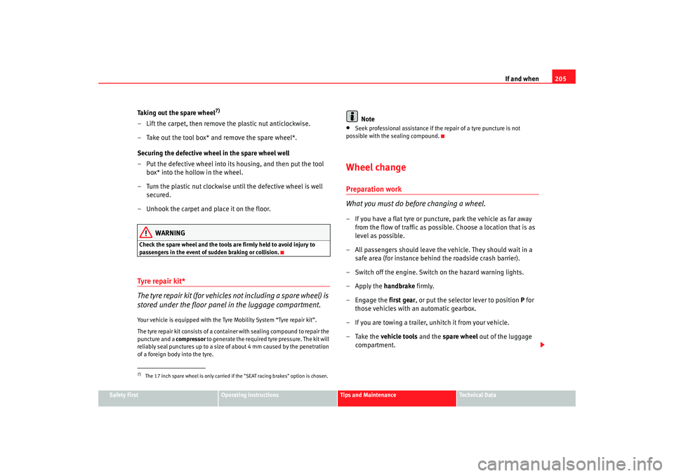
– Insert the extraction hook from the tools in the corresponding
hole ⇒fig. 139.
– Pull off the hub cap.
Wheel covers*
The wheel covers must be removed for access to the wheel
boltsDismantle
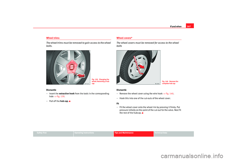
– Remove the wheel cover using the wire hook ⇒fig. 140.
– Hook this into one of the cut-outs of the wheel cover.
Fit
– Fit the wheel cover onto the wheel rim by pressing it firmly. Put pressure initially on the point of the cut-out for the valve. Next fit
the rest of the hubcap.
Fig. 139 Changing the
wheel: Removing a hub
cap
Fig. 140 Remove the
complete hub cap
IBI_ANG_0707 Seite 207 Montag, 6. August 2007 3:59 15
Page 211 of 272

If and when209
Safety First
Operating instructions
Tips and Maintenance
Te c h n i c a l D a t a
Raising the vehicle
The vehicle must be raised with a jack to remove the wheel.
– Locate the jacking point under the door sill closest to the wheel
to be changed ⇒fig. 142.
– Wind up the jack under the jacking point until the arm of the jack is directly below the vertical rib under the door sill.
– Align the jack so that the arm of the jack fits around the rib under the door sill and the movable base plate of the jack is flat on the
ground ⇒fig. 143.
– Raise the vehicle until the defect ive wheel is just clear of the
ground.Recesses at the front and rear of the door sills mark the jacking points
⇒ fig. 142 . A position has been made for each wheel. Do not fit the jack
anywhere else.
An unstable surface under the jack may cause the vehicle to slip off the jack.
Therefore, the jack must be fitted on solid ground offering good support. Use
a large and stable base, if necessary. On a hard, slippery surface (such as
tiles) use a rubber mat or similar to prevent the jack from slipping.
WARNING
•
Take all precautions so that the base of the jack does not slip. Failure to
do so could result in an accident.
•
The vehicle can be damaged if the jack is not applied at the correct
jacking points. There is also a risk of injury since the jack can slip off
suddenly if it is not properly engaged.
Fig. 142 The jacking
pointsFig. 143 Fitting the jack
IBI_ANG_0707 Seite 209 Montag, 6. August 2007 3:59 15
Page 213 of 272

If and when211
Safety First
Operating instructions
Tips and Maintenance
Te c h n i c a l D a t a
– Insert the adapter onto the wheel bolt and push it on as far as it
will go ⇒page 210, fig. 145 .
– Fit the box spanner as far as it will go over the adapter.
– Loosen or tighten the wheel bolt as appropriate.Error code
The code number of the anti-theft wheel bolt is stamped on the front of the
adaptor.
The code number should be noted and kept in a safe place, as it is only by
using the code number that a duplicat e adaptor can be obtained from an
Authorised Service Centre.Tyres with directional tread pattern
Tyres with directional tread pattern must be fitted so that they
rotate in the correct direction.A directional tread pattern can be identified by arrows on the sidewall that
point in the direction of rotation. Always note the direction of rotation indi-
cated when fitting the wheel. This is important so that these tyres can give
maximum grip and avoid excessive noise, tread wear and aquaplaning.
If, in an emergency, you have to fit th e spare wheel so it rotates in the wrong
direction, you must drive extremely care fully. The tyre will not give optimum
performance. This is particularly important when driving on wet roads.
To benefit from the advantages of tyres with this type of tread pattern, the
defective tyre should be replaced as soon as possible so that all tyres again
rotate in the correct direction.
Tyre repair kit* (Tyre Mobility System)General information and safety notesYour vehicle is equipped with a tyre repair kit: the Tyre Mobility System.
In the event of a tyre puncture, sealing compound and an air compressor are
located in the luggage compartment under the floor panel.
The Tyre Mobility System will reliably seal punctures caused by the penetra-
tion of a foreign body of up to about 4 mm in diameter.
It is not necessary to remove the foreign body from the tyre.
Instructions for the sealing compound are located on the sealing compound
container.
Notes for the proper use of the air compressor are included in an additional
instruction leaflet.
WARNING
•
Do not attempt to repair a puncture with the sealing compound if the
tyre has been damaged by driving the car after the tyre has lost its air.
•
Always observe warnings and follow instructions concerning
compressor and sealing compound carefully.
•
Do not drive faster than 80 km/h, avoid heavy acceleration, hard
braking and fast cornering.
•
Tyres which have been repaired with sealing compound are only suit-
able for temporary use over a short period. Therefore, please drive carefully
to the next available qualified workshop.For the sake of the environment
Used sealing compound containers should be disposed of at a proper facility.
IBI_ANG_0707 Seite 211 Montag, 6. August 2007 3:59 15
Page 215 of 272

If and when213
Safety First
Operating instructions
Tips and Maintenance
Te c h n i c a l D a t a
Note
The compressor should never be allowed to run for longer than 6 minutes.FusesChanging a fuse
If a fuse has blown it must be replacedfuse cover
– Switch off the ignition and the component concerned.
– Identify the fuse for the failed component ⇒page 215.
– Take the plastic clip from inside the fuse cover, fit it onto the blown fuse and pull the fuse out. – Replace the blown fuse (which will have a melted metal strip)
with a new fuse of the same ampere rating.
The individual electrical circuits are pr otected by fuses. The fuses are located
behind a cover at the left-hand end of the dash panel. In versions with the
steering wheel on the right the fuses are on the right-hand side of the instru-
ment panel, behind a cover.
The electric windows are protected by circuit breakers. These reset automat-
ically after a few seconds when the overload (caused for example by frozen
windows) has been corrected.
Colour coding of fuses
WARNING
Never “repair” damaged fuses and never replace them with fuses with a
higher rating. Failure to comply could re sult in fire. This could also cause
damage to other parts of the electrical system.
Note
•
If a newly replaced fuse blows again after a short time, the electrical
system must be checked by a qualified workshop as soon as possible.
Fig. 146 Fuses in the
dash panel
Colour Amperes
Beige 5
Brown 7,5 red 10
blue 15
yellow 20
natural (white) 25
green 30
IBI_ANG_0707 Seite 213 Montag, 6. August 2007 3:59 15