2007 NISSAN TIIDA winter
[x] Cancel search: winterPage 1468 of 5883
![NISSAN TIIDA 2007 Service Repair Manual TROUBLE DIAGNOSIS - SPECIFICATION VALUE
EC-119
< COMPONENT DIAGNOSIS >[HR16DE (WITH EURO-OBD)]
C
D
E
F
G
H
I
J
K
L
MA
EC
N
P O
NOTE:
Check “A/F ALPHA-B1” for approximately 1 minute because they ma](/manual-img/5/57395/w960_57395-1467.png "NISSAN TIIDA 2007 Service Repair Manual TROUBLE DIAGNOSIS - SPECIFICATION VALUE
EC-119
< COMPONENT DIAGNOSIS >[HR16DE (WITH EURO-OBD)]
C
D
E
F
G
H
I
J
K
L
MA
EC
N
P O
NOTE:
Check “A/F ALPHA-B1” for approximately 1 minute because they ma")
TROUBLE DIAGNOSIS - SPECIFICATION VALUE
EC-119
< COMPONENT DIAGNOSIS >[HR16DE (WITH EURO-OBD)]
C
D
E
F
G
H
I
J
K
L
MA
EC
N
P O
NOTE:
Check “A/F ALPHA-B1” for approximately 1 minute because they may fluctuate. It is NG if the indication is
out of the SP value even a little.
Is the measurement value within the SP value?
YES >> GO TO 17.
NO-1 >> Less than the SP value: GO TO 2.
NO-2 >> More than the SP value: GO TO 3.
2.CHECK “B/FUEL SCHDL”
Select “B/FUEL SCHDL” in “SPEC” of “DATA MONITOR” mode, and make sure that the indication is within the
SP value.
Is the measurement value within the SP value?
YES >> GO TO 4.
NO >> More than the SP value: GO TO 19.
3.CHECK “B/FUEL SCHDL”
Select “B/FUEL SCHDL” in “SPEC” of “DATA MONITOR” mode, and make sure that the indication is within the
SP value.
Is the measurement value within the SP value?
YES >> GO TO 6.
NO-1 >> More than the SP value: GO TO 6.
NO-2 >> Less than the SP value: GO TO 25.
4.CHECK “A/F ALPHA-B1”
1. Stop the engine.
2. Disconnect PCV hose, and then plug it.
3. Start engine.
4. Select “A/F ALPHA-B1” in “SPEC” of “DATA MONITOR” mode, and make sure that the indication is within
the SP value.
Is the measurement value within the SP value?
YES >> GO TO 5.
NO >> GO TO 6.
5.CHANGE ENGINE OIL
1. Stop the engine.
2. Change engine oil.
NOTE:
This symptom may occur when a large amount of gasoline is mixed with engine oil because of driving
conditions (such as when engine oil temperature does not rise enough since a journey distance is too
short during winter). The symptom will not be detected after changing engine oil or changing driving con-
dition.
>>INSPECTION END
6.CHECK FUEL PRESSURE
Check fuel pressure. (Refer to EC-377, "
Inspection".)
Is the inspection result normal?
YES >> GO TO 9.
NO-1 >> Fuel pressure is too high: Replace “fuel filter and fuel pump assembly” and then GO TO 8.
NO-2 >> Fuel pressure is too low: GO TO 7.
7.DETECT MALFUNCTIONING PART
Check fuel hoses and fuel tubes for clogging
Is the inspection result normal?
YES >> Replace “fuel filter and fuel pump assembly” and then GO TO 8.
NO >> Repair or replace and then GO TO 8.
8.CHECK “A/F ALPHA-B1”
Page 1821 of 5883
![NISSAN TIIDA 2007 Service Repair Manual EC-472
< COMPONENT DIAGNOSIS >[HR16DE (WITHOUT EURO-OBD)]
TROUBLE DIAGNOSIS - SPECIFICATION VALUE
NOTE:
Check “A/F ALPHA-B1” for approximately 1 minute because they may fluctuate. It is NG if the](/manual-img/5/57395/w960_57395-1820.png "NISSAN TIIDA 2007 Service Repair Manual EC-472
< COMPONENT DIAGNOSIS >[HR16DE (WITHOUT EURO-OBD)]
TROUBLE DIAGNOSIS - SPECIFICATION VALUE
NOTE:
Check “A/F ALPHA-B1” for approximately 1 minute because they may fluctuate. It is NG if the")
EC-472
< COMPONENT DIAGNOSIS >[HR16DE (WITHOUT EURO-OBD)]
TROUBLE DIAGNOSIS - SPECIFICATION VALUE
NOTE:
Check “A/F ALPHA-B1” for approximately 1 minute because they may fluctuate. It is NG if the indication is
out of the SP value even a little.
Is the measurement value within the SP value?
YES >> GO TO 17.
NO-1 >> Less than the SP value: GO TO 2.
NO-2 >> More than the SP value: GO TO 3.
2.CHECK “B/FUEL SCHDL”
Select “B/FUEL SCHDL” in “SPEC” of “DATA MONITOR” mode, and make sure that the indication is within the
SP value.
Is the measurement value within the SP value?
YES >> GO TO 4.
NO >> More than the SP value: GO TO 19.
3.CHECK “B/FUEL SCHDL”
Select “B/FUEL SCHDL” in “SPEC” of “DATA MONITOR” mode, and make sure that the indication is within the
SP value.
Is the measurement value within the SP value?
YES >> GO TO 6.
NO-1 >> More than the SP value: GO TO 6.
NO-2 >> Less than the SP value: GO TO 25.
4.CHECK “A/F ALPHA-B1”
1. Stop the engine.
2. Disconnect PCV hose, and then plug it.
3. Start engine.
4. Select “A/F ALPHA-B1” in “SPEC” of “DATA MONITOR” mode, and make sure that the indication is within
the SP value.
Is the measurement value within the SP value?
YES >> GO TO 5.
NO >> GO TO 6.
5.CHANGE ENGINE OIL
1. Stop the engine.
2. Change engine oil.
NOTE:
This symptom may occur when a large amount of gasoline is mixed with engine oil because of driving
conditions (such as when engine oil temperature does not rise enough since a journey distance is too
short during winter). The symptom will not be detected after changing engine oil or changing driving con-
dition.
>>INSPECTION END
6.CHECK FUEL PRESSURE
Check fuel pressure. (Refer to EC-681, "
Inspection".)
Is the inspection result normal?
YES >> GO TO 9.
NO-1 >> Fuel pressure is too high: Replace “fuel filter and fuel pump assembly” and then GO TO 8.
NO-2 >> Fuel pressure is too low: GO TO 7.
7.DETECT MALFUNCTIONING PART
Check fuel hoses and fuel tubes for clogging
Is the inspection result normal?
YES >> Replace “fuel filter and fuel pump assembly” and then GO TO 8.
NO >> Repair or replace and then GO TO 8.
8.CHECK “A/F ALPHA-B1”
Page 2133 of 5883
![NISSAN TIIDA 2007 Service Repair Manual EC-784
< COMPONENT DIAGNOSIS >[MR18DE]
TROUBLE DIAGNOSIS - SPECIFICATION VALUE
NOTE:
Check “A/F ALPHA-B1” for approximately 1 minute because they may fluctuate. It is NG if the indication is
out o](/manual-img/5/57395/w960_57395-2132.png "NISSAN TIIDA 2007 Service Repair Manual EC-784
< COMPONENT DIAGNOSIS >[MR18DE]
TROUBLE DIAGNOSIS - SPECIFICATION VALUE
NOTE:
Check “A/F ALPHA-B1” for approximately 1 minute because they may fluctuate. It is NG if the indication is
out o")
EC-784
< COMPONENT DIAGNOSIS >[MR18DE]
TROUBLE DIAGNOSIS - SPECIFICATION VALUE
NOTE:
Check “A/F ALPHA-B1” for approximately 1 minute because they may fluctuate. It is NG if the indication is
out of the SP value even a little.
Is the measurement value within the SP value?
YES >> GO TO 17.
NO-1 >> Less than the SP value: GO TO 2.
NO-2 >> More than the SP value: GO TO 3.
2.CHECK “B/FUEL SCHDL”
Select “B/FUEL SCHDL” in “SPEC” of “DATA MONITOR” mode, and make sure that the indication is within the
SP value.
Is the measurement value within the SP value?
YES >> GO TO 4.
NO >> More than the SP value: GO TO 19.
3.CHECK “B/FUEL SCHDL”
Select “B/FUEL SCHDL” in “SPEC” of “DATA MONITOR” mode, and make sure that the indication is within the
SP value.
Is the measurement value within the SP value?
YES >> GO TO 6.
NO-1 >> More than the SP value: GO TO 6.
NO-2 >> Less than the SP value: GO TO 25.
4.CHECK “A/F ALPHA-B1”
1. Stop the engine.
2. Disconnect PCV hose, and then plug it.
3. Start engine.
4. Select “A/F ALPHA-B1” in “SPEC” of “DATA MONITOR” mode, and make sure that the indication is within
the SP value.
Is the measurement value within the SP value?
YES >> GO TO 5.
NO >> GO TO 6.
5.CHANGE ENGINE OIL
1. Stop the engine.
2. Change engine oil.
NOTE:
This symptom may occur when a large amount of gasoline is mixed with engine oil because of driving
conditions (such as when engine oil temperature does not rise enough since a journey distance is too
short during winter). The symptom will not be detected after changing engine oil or changing driving con-
dition.
>>INSPECTION END
6.CHECK FUEL PRESSURE
Check fuel pressure. (Refer to EC-1035, "
Inspection".)
Is the inspection result normal?
YES >> GO TO 9.
NO-1 >> Fuel pressure is too high: Replace “fuel filter and fuel pump assembly” and then GO TO 8.
NO-2 >> Fuel pressure is too low: GO TO 7.
7.DETECT MALFUNCTIONING PART
Check fuel hoses and fuel tubes for clogging
Is the inspection result normal?
YES >> Replace “fuel filter and fuel pump assembly” and then GO TO 8.
NO >> Repair or replace and then GO TO 8.
8.CHECK “A/F ALPHA-B1”
Page 3251 of 5883
SERVICE INFORMATION FOR ELECTRICAL INCIDENT
GI-57
< BASIC INSPECTION >
C
D
E
F
G
H
I
J
K
L
MB
GI
N
O
P
An unclamped or loose harness can cause wiring to be pinched by seat components (such as slide guides)
during vehicle vibration. If the wiring runs under seating areas, inspect wire routing for possible damage or
pinching.
HEAT SENSITIVE
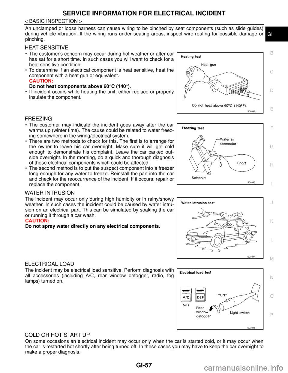
The customer's concern may occur during hot weather or after car
has sat for a short time. In such cases you will want to check for a
heat sensitive condition.
To determine if an electrical component is heat sensitive, heat the
component with a heat gun or equivalent.
CAUTION:
Do not heat components above 60°C (140°).
If incident occurs while heating the unit, either replace or properly
insulate the component.
FREEZING
The customer may indicate the incident goes away after the car
warms up (winter time). The cause could be related to water freez-
ing somewhere in the wiring/electrical system.
There are two methods to check for this. The first is to arrange for
the owner to leave his car overnight. Make sure it will get cold
enough to demonstrate his complaint. Leave the car parked out-
side overnight. In the morning, do a quick and thorough diagnosis
of those electrical components which could be affected.
The second method is to put the suspect component into a freezer
long enough for any water to freeze. Reinstall the part into the car
and check for the reoccurrence of the incident. If it occurs, repair or
replace the component.
WATER INTRUSION
The incident may occur only during high humidity or in rainy/snowy
weather. In such cases the incident could be caused by water intru-
sion on an electrical part. This can be simulated by soaking the car
or running it through a car wash.
CAUTION:
Do not spray water directly on any electrical components.
ELECTRICAL LOAD
The incident may be electrical load sensitive. Perform diagnosis with
all accessories (including A/C, rear window defogger, radio, fog
lamps) turned on.
COLD OR HOT START UP
On some occasions an electrical incident may occur only when the car is started cold, or it may occur when
the car is restarted hot shortly after being turned off. In these cases you may have to keep the car overnight to
make a proper diagnosis.
SGI842
SGI843
SGI844
SGI845
Page 4306 of 5883
MIR-8
< REMOVAL AND INSTALLATION >
DOOR MIRROR
Disassembly and Assembly
INFOID:0000000001716809
DISASSEMBLY
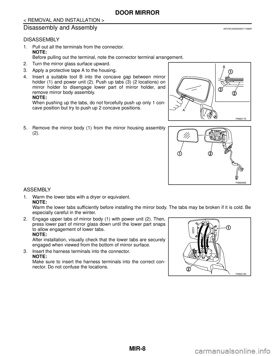
1. Pull out all the terminals from the connector.
NOTE:
Before pulling out the terminal, note the connector terminal arrangement.
2. Turn the mirror glass surface upward.
3. Apply a protective tape A to the housing.
4. Insert a suitable tool B into the concave gap between mirror
holder (1) and power unit (2). Push up tabs (3) (2 locations) on
mirror holder to disengage lower part of mirror holder, and
remove mirror body assembly.
NOTE:
When pushing up the tabs, do not forcefully push up only 1 con-
cave position but try to push up 2 concave positions.
5. Remove the mirror body (1) from the mirror housing assembly
(2).
ASSEMBLY
1. Warm the lower tabs with a dryer or equivalent.
NOTE:
Warm the lower tabs sufficiently before installing the mirror body. The tabs may be broken if it is cold. Be
especially careful in the winter.
2. Engage upper tabs of mirror body (1) with power unit (2). Then,
press lower part of mirror glass down until the lower part snaps
to allow engagement of lower tabs.
NOTE:
After installation, visually check that the lower tabs are securely
engaged when viewed from the bottom of mirror surface.
3. Insert the harness terminals into the connector.
NOTE:
Make sure to insert the harness terminals into the correct con-
nector. Do not confuse the locations.
PIIB6317E
PIIB6096E
PIIB6316E