2007 NISSAN TIIDA Safe entry system
[x] Cancel search: Safe entry systemPage 600 of 5883

DLK-11
C
D
E
F
G
H
I
J
L
MA
B
DLK
N
O
P BACK DOOR : Description ....................................
534
BACK DOOR : Component Function Check .......534
BACK DOOR : Diagnosis Procedure ....................534
BACK DOOR : Component Inspection ..................536
TRUNK LID OPENER ACTUATOR .................537
Description ............................................................537
Component Function Check ................................537
Diagnosis Procedure .............................................537
Component Inspection ..........................................538
BUZZER (COMBINATION METER) .................540
Description ............................................................540
Component Function Check ................................540
Diagnosis Procedure .............................................540
HAZARD WARNING LAMPS ...........................541
Description ............................................................541
Component Function Check ................................541
Diagnosis Procedure .............................................541
VEHICLE SPEED SIGNAL CIRCUIT ...............542
Description ............................................................542
Component Function Check ................................542
Diagnosis Procedure .............................................542
KEYFOB BATTERY AND FUNCTION .............543
Description ............................................................543
Component Function Check ................................543
Diagnosis Procedure .............................................543
Component Inspection ..........................................543
Special Repair Requirement .................................543
ECU DIAGNOSIS .......................................544
BCM (BODY CONTROL MODULE) .................544
Reference Value ...................................................544
Wiring Diagram - POWER DOOR LOCK SYSTEM
- .............................................................................
544
Wiring Diagram - REMOTE KEYLESS ENTRY
SYSTEM - .............................................................
552
Wiring Diagram - BACK DOOR OPENER SYS-
TEM - ....................................................................
558
Wiring Diagram - TRUNK LID OPENER SYSTEM
- .............................................................................
562
Fail Safe ...............................................................564
DTC Inspection Priority Chart .............................565
DTC Index ............................................................565
SYMPTOM DIAGNOSIS ............................567
DOOR LOCK FUNCTION SYMPTOMS ...........567
DOOR LOCK AND UNLOCK SWITCH ...................567
DOOR LOCK AND UNLOCK SWITCH : Symptom
Table .....................................................................
567
KEYFOB ..................................................................567
KEYFOB : Symptom Table ...................................567
BACK DOOR OPEN FUNCTION SYMPTOMS
..
569
BACK DOOR OPENER SWITCH ............................569
BACK DOOR OPENER SWITCH : Symptom Ta-
ble ..........................................................................
569
TRUNK OPEN FUNCTION SYMPTOMS ........570
TRUNK LID OPENER SWITCH ...............................570
TRUNK LID OPENER SWITCH : Symptom Table ..570
WARNING FUNCTION SYMPTOMS ..............571
BACK DOOR ...........................................................571
BACK DOOR : Symptom Table .............................571
HAZARD REMINDER FUNCTION ..................572
HAZARD WARNING LAMP .....................................572
HAZARD WARNING LAMP : Symptom Table ......572
SQUEAK AND RATTLE TROUBLE DIAG-
NOSES ............................................................
573
Work Flow ..............................................................573
Inspection Procedure .............................................575
Diagnostic Worksheet ............................................577
PRECAUTION ............................................579
PRECAUTIONS ...............................................579
Precaution for Supplemental Restraint System
(SRS) "AIR BAG" and "SEAT BELT PRE-TEN-
SIONER" ...............................................................
579
Procedure without Cowl Top Cover ....................579
Steering Wheel Rotation after Battery Disconn
ect ..........................................................................
579
Work ......................................................................580
PREPARATION .........................................581
PREPARATION ...............................................581
Commercial Service Tool ......................................581
ON-VEHICLE MAINTENANCE ..................582
PRE-INSPECTION FOR DIAGNOSTIC ..........582
Basic Inspection ....................................................582
REMOVAL AND INSTALLATION .............583
HOOD ..............................................................583
Fitting Adjustment ..................................................583
Removal and Installation .......................................584
Removal and Installation of Hood Lock Control ....585
Hood Lock Control Inspection ...............................587
RADIATOR CORE SUPPORT ........................589
Removal and Installation .......................................589
FRONT FENDER .............................................591
Removal and Installation .......................................591
DOOR ..............................................................592
Fitting Adjustment ..................................................592
Removal and Installation .......................................595
Page 603 of 5883

DLK-14
REAR LH ..................................................................681
REAR LH : Description ..........................................681
REAR LH : Component Function Check ..............681
REAR LH : Diagnosis Procedure ...........................681
REAR RH .................................................................682
REAR RH : Description .........................................682
REAR RH : Component Function Check .............682
REAR RH : Diagnosis Procedure ..........................683
TRUNK LID OPENER ACTUATOR .................685
Description .............................................................685
Component Function Check ................................685
Diagnosis Procedure .............................................685
Component Inspection ...........................................686
BUZZER (COMBINATION METER) ................688
Description .............................................................688
Component Function Check ................................688
Diagnosis Procedure .............................................688
HAZARD WARNING LAMPS ..........................689
Description .............................................................689
Component Function Check ................................689
Diagnosis Procedure .............................................689
VEHICLE SPEED SIGNAL CIRCUIT ..............690
Description .............................................................690
Component Function Check ................................690
Diagnosis Procedure .............................................690
KEYFOB BATTERY AND FUNCTION ............691
Description .............................................................691
Component Function Check ................................691
Diagnosis Procedure .............................................691
Component Inspection ...........................................691
Special Repair Requirement ..................................691
ECU DIAGNOSIS .......................................692
BCM (BODY CONTROL MODULE) ................692
Reference Value ....................................................692
Wiring Diagram - POWER DOOR LOCK SYSTEM
- .............................................................................
693
Wiring Diagram - REMOTE KEYLESS ENTRY
SYSTEM - ..............................................................
703
Wiring Diagram - BACK DOOR OPENER SYS-
TEM - .....................................................................
709
Wiring Diagram - TRUNK LID OPENER SYSTEM
- .............................................................................
713
Fail Safe ................................................................715
DTC Inspection Priority Chart .............................716
DTC Index .............................................................716
SYMPTOM DIAGNOSIS ............................718
DOOR LOCK FUNCTION SYMPTOMS ..........718
DOOR LOCK AND UNLOCK SWITCH ...................718
DOOR LOCK AND UNLOCK SWITCH : Symptom
Table ......................................................................
718
KEYFOB ..................................................................718
KEYFOB : Symptom Table ...................................719
BACK DOOR OPEN FUNCTION SYMPTOMS
..
720
BACK DOOR OPENER SWITCH ...........................720
BACK DOOR OPENER SWITCH : Symptom Ta-
ble .........................................................................
720
TRUNK OPEN FUNCTION SYMPTOMS .........721
TRUNK LID OPENER SWITCH ..............................721
TRUNK LID OPENER SWITCH : Symptom Table .721
WARNING FUNCTION SYMPTOMS ...............722
BACK DOOR ...........................................................722
BACK DOOR : Symptom Table ............................722
HAZARD REMINDER FUNCTION ...................723
HAZARD WARNING LAMP ....................................723
HAZARD WARNING LAMP : Symptom Table ......723
SQUEAK AND RATTLE TROUBLE DIAG-
NOSES ..............................................................
724
Work Flow .............................................................724
Inspection Procedure ............................................726
Diagnostic Worksheet ...........................................728
PRECAUTION ...........................................730
PRECAUTIONS ................................................730
Precaution for Supplemental Restraint System
(SRS) "AIR BAG" and "SEAT BELT PRE-TEN-
SIONER" ...............................................................
730
Procedure without Cowl Top Cover ...................730
Steering Wheel Rotation after Battery Disconn
ect .........................................................................
730
Work ......................................................................731
PREPARATION .........................................732
PREPARATION ................................................732
Commercial Service Tool ......................................732
ON-VEHICLE MAINTENANCE .................733
PRE-INSPECTION FOR DIAGNOSTIC ...........733
Basic Inspection ....................................................733
REMOVAL AND INSTALLATION .............734
HOOD ...............................................................734
Fitting Adjustment .................................................734
Removal and Installation .......................................735
Removal and Installation of Hood Lock Control ....736
Hood Lock Control Inspection ...............................738
RADIATOR CORE SUPPORT .........................740
Removal and Installation .......................................740
Page 612 of 5883

DOOR LOCK FUNCTION
DLK-23
< FUNCTION DIAGNOSIS >[WITH I-KEY, WITHOUT SUPER LOCK]
C
D
E
F
G
H
I
J
L
MA
B
DLK
N
O
P
DOOR LOCK AND UNLOCK SWITCH : Component DescriptionINFOID:0000000001396465
INTELLIGENT KEY
INTELLIGENT KEY : System DiagramINFOID:0000000001396466
INTELLIGENT KEY OPERATION
INTELLIGENT KEY : System DescriptionINFOID:0000000001396467
INTELLIGENT KEY OPERATION
The Intelligent Key has the same functions as the remote keyless entry system. In addition to other safety fea-
tures, it can be used to lock and unlock all doors including the back door (hatchback) or the trunk (sedan).
This function can be set to OFF with CONSULT-III. For the setting information, refer to DLK-53, "
CONSULT-III
Function (INTELLIGENT KEY)".
OPERATION CONDITION
OPERATION AREA
To ensure that the Intelligent Key works effectively, use within a 100 cm range of each door, however the oper-
able range may differ according to surroundings.
DOOR LOCK AND UNLOCK CONTROL
When door lock and unlock button of the Intelligent Key are pressed, lock signal or unlock signal is transmitted
from Intelligent Key to Intelligent Key unit.
When Intelligent Key unit receives the door lock and unlock signal, it operates door lock actuator.
Item Function
BCM Controls the door lock function.
Door switch Detects door state (open or close).
Door lock and unlock switchTransmits door lock/unlock signal to BCM. Door lock/unlock switch indicator is built-in door
lock and unlock switch.
Door lock actuator Receives door lock/unlock signal from BCM and locks/unlocks each door.
ALKIA0711GB
Remote controller operation Operation condition
Lock All doors are closed
Key switch is OFF (key is removed from ignition key cylinder)
Ignition knob switch is OFF (Ignition switch is not pressed)
Unlock Key switch is OFF (key is removed from ignition key cylinder)
Ignition knob switch is OFF (Ignition switch is not pressed)
Page 3285 of 5883
PRECAUTIONS
HA-3
< PRECAUTION >
C
D
E
F
G
H
J
K
L
MA
B
HA
N
O
P
PRECAUTION
PRECAUTIONS
Precaution for Supplemental Restraint System (SRS) "AIR BAG" and "SEAT BELT
PRE-TENSIONER"
INFOID:0000000001396449
The Supplemental Restraint System such as “AIR BAG” and “SEAT BELT PRE-TENSIONER”, used along
with a front seat belt, helps to reduce the risk or severity of injury to the driver and front passenger for certain
types of collision. Information necessary to service the system safely is included in the SR and SB section of
this Service Manual.
WARNING:
• To avoid rendering the SRS inoperative, which could increase the risk of personal injury or death in
the event of a collision which would result in air bag inflation, all maintenance must be performed by
an authorized NISSAN/INFINITI dealer.
Improper maintenance, including incorrect removal and installation of the SRS, can lead to personal
injury caused by unintentional activation of the system. For removal of Spiral Cable and Air Bag
Module, see the SR section.
Do not use electrical test equipment on any circuit related to the SRS unless instructed to in this
Service Manual. SRS wiring harnesses can be identified by yellow and/or orange harnesses or har-
ness connectors.
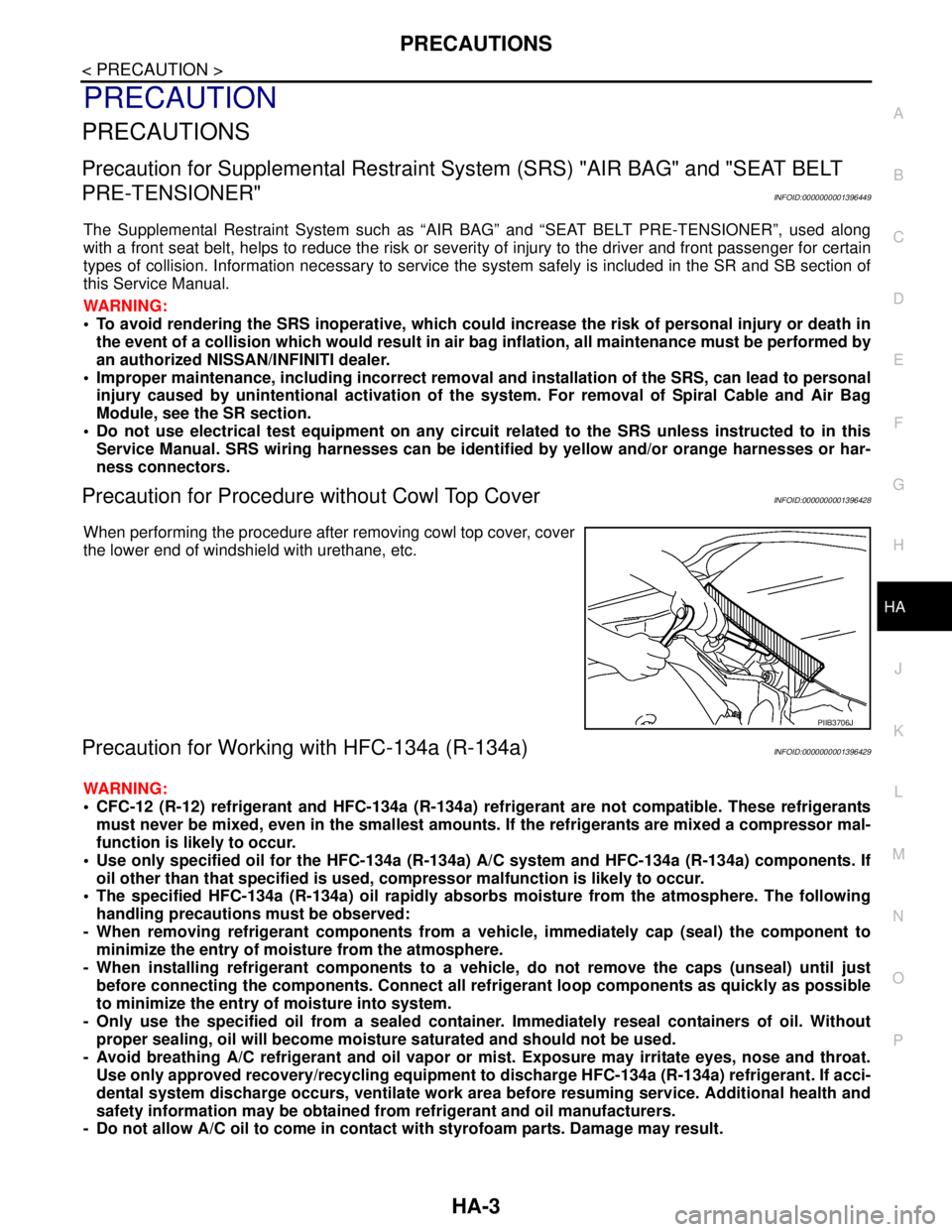
Precaution for Procedure without Cowl Top CoverINFOID:0000000001396428
When performing the procedure after removing cowl top cover, cover
the lower end of windshield with urethane, etc.
Precaution for Working with HFC-134a (R-134a)INFOID:0000000001396429
WARNING:
CFC-12 (R-12) refrigerant and HFC-134a (R-134a) refrigerant are not compatible. These refrigerants
must never be mixed, even in the smallest amounts. If the refrigerants are mixed a compressor mal-
function is likely to occur.
Use only specified oil for the HFC-134a (R-134a) A/C system and HFC-134a (R-134a) components. If
oil other than that specified is used, compressor malfunction is likely to occur.
The specified HFC-134a (R-134a) oil rapidly absorbs moisture from the atmosphere. The following
handling precautions must be observed:
- When removing refrigerant components from a vehicle, immediately cap (seal) the component to
minimize the entry of moisture from the atmosphere.
- When installing refrigerant components to a vehicle, do not remove the caps (unseal) until just
before connecting the components. Connect all refrigerant loop components as quickly as possible
to minimize the entry of moisture into system.
- Only use the specified oil from a sealed container. Immediately reseal containers of oil. Without
proper sealing, oil will become moisture saturated and should not be used.
- Avoid breathing A/C refrigerant and oil vapor or mist. Exposure may irritate eyes, nose and throat.
Use only approved recovery/recycling equipment to discharge HFC-134a (R-134a) refrigerant. If acci-
dental system discharge occurs, ventilate work area before resuming service. Additional health and
safety information may be obtained from refrigerant and oil manufacturers.
- Do not allow A/C oil to come in contact with styrofoam parts. Damage may result.
PIIB3706J
Page 3286 of 5883
HA-4
< PRECAUTION >
PRECAUTIONS
General Refrigerant Precaution
INFOID:0000000001396430
WARNING:
Avoid breathing A/C refrigerant and oil vapor or mist. Exposure may irritate eyes, nose and throat.
Use only approved recovery/recycling equipment to discharge HFC-134a (R-134a) refrigerant. If acci-
dental system discharge occurs, ventilate work area before resuming service. Additional health and
safety information may be obtained from refrigerant and oil manufacturers.
Do not release refrigerant into the air. Use approved recovery/recycling equipment to capture the
refrigerant every time an air conditioning system is discharged.
Always wear eye and hand protection (goggles and gloves) when working with any refrigerant or air
conditioning system.
Do not store or heat refrigerant containers above 52°C (126° F).
Do not heat a refrigerant container with an open flame; if container warming is required, place the
bottom of the container in a warm pail of water.
Do not intentionally drop, puncture, or incinerate refrigerant containers.
Keep refrigerant away from open flames: poisonous gas will be produced if refrigerant burns.
Refrigerant will displace oxygen, therefore be certain to work in well ventilated areas to prevent suf-
focation.
Do not pressure test or leak test HFC-134a (R-134a) service equipment and/or vehicle air condition-
ing systems with compressed air during repair. Some mixtures of air and HFC-134a (R-134a) have
been shown to be combustible at elevated pressures. These mixtures, if ignited, may cause injury or
property damage. Additional health and safety information may be obtained from refrigerant manu-
facturers.
Oil PrecautionINFOID:0000000001396431
Use only specified oil for the HFC-134a (R-134a) A/C system and HFC-134a (R-134a) components. If oil
other than that specified is used, compressor malfunction is likely to occur.
The specified HFC-134a (R-134a) oil rapidly absorbs moisture from the atmosphere. The following handling
precautions must be observed:
- When removing refrigerant components from a vehicle, immediately cap (seal) the component to minimize
the entry of moisture from the atmosphere.
- When installing refrigerant components to a vehicle, do not remove the caps (unseal) until just before con-
necting the components. Connect all refrigerant loop components as quickly as possible to minimize the
entry of moisture into system.
- Only use the specified oil from a sealed container. Immediately reseal containers of oil. Without proper seal-
ing, oil will become moisture saturated and should not be used.
Avoid breathing A/C refrigerant and oil vapor or mist. Exposure may irritate eyes, nose and throat.
Use only approved recovery/recycling equipment to discharge HFC-134a (R-134a) refrigerant. If accidental
system discharge occurs, ventilate work area before resuming service. Additional health and safety informa-
tion may be obtained from refrigerant and oil manufacturers.
Do not allow A/C oil to come in contact with styrofoam parts. Damage may result.
Precaution for Refrigerant ConnectionINFOID:0000000001396432
A new type refrigerant connection has been introduced to all refrigerant lines except the following location.
Expansion valve to evaporator
Refrigerant pressure sensor to condenser
Page 3417 of 5883

HAC-84
< PRECAUTION >[MANUAL AIR CONDITIONER]
PRECAUTIONS
PRECAUTION
PRECAUTIONS
Precaution for Supplemental Restraint System (SRS) "AIR BAG" and "SEAT BELT
PRE-TENSIONER"
INFOID:0000000001683796
The Supplemental Restraint System such as “AIR BAG” and “SEAT BELT PRE-TENSIONER”, used along
with a front seat belt, helps to reduce the risk or severity of injury to the driver and front passenger for certain
types of collision. Information necessary to service the system safely is included in the SRS and SB section of
this Service Manual.
WARNING:
• To avoid rendering the SRS inoperative, which could increase the risk of personal injury or death in
the event of a collision which would result in air bag inflation, all maintenance must be performed by
an authorized NISSAN/INFINITI dealer.
Improper maintenance, including incorrect removal and installation of the SRS, can lead to personal
injury caused by unintentional activation of the system. For removal of Spiral Cable and Air Bag
Module, see the SRS section.
Do not use electrical test equipment on any circuit related to the SRS unless instructed to in this
Service Manual. SRS wiring harnesses can be identified by yellow and/or orange harnesses or har-
ness connectors.
Precaution for Procedures Without Cowl Top CoverINFOID:0000000001203084
When performing the procedure after removing cowl top cover, cover
the lower end of windshield with urethane, etc.
Working with HFC-134a (R-134a)INFOID:0000000001203085
WARNING:
CFC-12 (R-12) refrigerant and HFC-134a (R-134a) refrigerant are not compatible. These refrigerants
must never be mixed, even in the smallest amounts. If the refrigerants are mixed a compressor mal-
function is likely to occur.
Use only specified oil for the HFC-134a (R-134a) A/C system and HFC-134a (R-134a) components. If
oil other than that specified is used, compressor malfunction is likely to occur.
The specified HFC-134a (R-134a) oil rapidly absorbs moisture from the atmosphere. The following
handling precautions must be observed:
- When removing refrigerant components from a vehicle, immediately cap (seal) the component to
minimize the entry of moisture from the atmosphere.
- When installing refrigerant components to a vehicle, do not remove the caps (unseal) until just
before connecting the components. Connect all refrigerant loop components as quickly as possible
to minimize the entry of moisture into system.
- Only use the specified oil from a sealed container. Immediately reseal containers of oil. Without
proper sealing, oil will become moisture saturated and should not be used.
- Avoid breathing A/C refrigerant and oil vapor or mist. Exposure may irritate eyes, nose and throat.
Use only approved recovery/recycling equipment to discharge HFC-134a (R-134a) refrigerant. If acci-
dental system discharge occurs, ventilate work area before resuming service. Additional health and
safety information may be obtained from refrigerant and oil manufacturers.
- Do not allow A/C oil to come in contact with styrofoam parts. Damage may result.
PIIB3706J
Page 3532 of 5883

PRECAUTIONS
HAC-199
< PRECAUTION >[AUTO AIR CONDITIONER (W/O NAVI)]
C
D
E
F
G
H
J
K
L
MA
B
HAC
N
O
P
PRECAUTION
PRECAUTIONS
Precaution for Supplemental Restraint System (SRS) "AIR BAG" and "SEAT BELT
PRE-TENSIONER"
INFOID:0000000001548138
The Supplemental Restraint System such as “AIR BAG” and “SEAT BELT PRE-TENSIONER”, used along
with a front seat belt, helps to reduce the risk or severity of injury to the driver and front passenger for certain
types of collision. Information necessary to service the system safely is included in the SRS and SB section of
this Service Manual.
WARNING:
To avoid rendering the SRS inoperative, which could increase the risk of personal injury or death in
the event of a collision which would result in air bag inflation, all maintenance must be performed by
an authorized NISSAN/INFINITI dealer.
Improper maintenance, including incorrect removal and installation of the SRS, can lead to personal
injury caused by unintentional activation of the system. For removal of Spiral Cable and Air Bag
Module, see the SRS section.
Do not use electrical test equipment on any circuit related to the SRS unless instructed to in this
Service Manual. SRS wiring harnesses can be identified by yellow and/or orange harnesses or har-
ness connectors.
Precaution for Procedures Without Cowl Top CoverINFOID:0000000001548139
When performing the procedure after removing cowl top cover, cover
the lower end of windshield with urethane, etc.
Working with HFC-134a (R-134a)INFOID:0000000001547461
WARNING:
CFC-12 (R-12) refrigerant and HFC-134a (R-134a) refrigerant are not compatible. If the refrigerants
are mixed compressor failure is likely to occur. Refer to XX-XX, "*****"
. To determine the purity of
HFC-134a (R-134a) in the vehicle and recovery tank, use Refrigerant Recovery/Recycling Recharging
equipment and Refrigerant Identifier.
Use only specified oil for the HFC-134a (R-134a) A/C system and HFC-134a (R-134a) components. If
oil other than that specified is used, compressor failure is likely to occur.
The specified HFC-134a (R-134a) oil rapidly absorbs moisture from the atmosphere. The following
handling precautions must be observed:
- When removing refrigerant components from a vehicle, immediately cap (seal) the component to
minimize the entry of moisture from the atmosphere.
- When installing refrigerant components to a vehicle, do not remove the caps (unseal) until just
before connecting the components. Connect all refrigerant loop components as quickly as possible
to minimize the entry of moisture into system.
- Only use the specified oil from a sealed container. Immediately reseal containers of oil. Without
proper sealing, oil will become moisture saturated and should not be used.
- Avoid breathing A/C refrigerant and oil vapor or mist. Exposure may irritate eyes, nose and throat.
Remove HFC-134a (R-134a) from the A/C system using certified service equipment meeting require-
ments of SAE J2210 [HFC-134a (R-134a) recycling equipment], or J2209 [HFC-134a (R-134a) recy-
cling equipment], If accidental system discharge occurs, ventilate work area before resuming
service. Additional health and safety information may be obtained from refrigerant and oil manufac-
turers.
PIIB3706J
Page 3646 of 5883

PRECAUTIONS
HAC-313
< PRECAUTION >[AUTO AIR CONDITIONER (W/NAVI)]
C
D
E
F
G
H
J
K
L
MA
B
HAC
N
O
P
PRECAUTION
PRECAUTIONS
Precaution for Supplemental Restraint System (SRS) "AIR BAG" and "SEAT BELT
PRE-TENSIONER"
INFOID:0000000001548120
The Supplemental Restraint System such as “AIR BAG” and “SEAT BELT PRE-TENSIONER”, used along
with a front seat belt, helps to reduce the risk or severity of injury to the driver and front passenger for certain
types of collision. Information necessary to service the system safely is included in the SRS and SB section of
this Service Manual.
WARNING:
To avoid rendering the SRS inoperative, which could increase the risk of personal injury or death in
the event of a collision which would result in air bag inflation, all maintenance must be performed by
an authorized NISSAN/INFINITI dealer.
Improper maintenance, including incorrect removal and installation of the SRS, can lead to personal
injury caused by unintentional activation of the system. For removal of Spiral Cable and Air Bag
Module, see the SRS section.
Do not use electrical test equipment on any circuit related to the SRS unless instructed to in this
Service Manual. SRS wiring harnesses can be identified by yellow and/or orange harnesses or har-
ness connectors.
Precaution for Procedures Without Cowl Top CoverINFOID:0000000001548121
When performing the procedure after removing cowl top cover, cover
the lower end of windshield with urethane, etc.
Working with HFC-134a (R-134a)INFOID:0000000001547383
WARNING:
CFC-12 (R-12) refrigerant and HFC-134a (R-134a) refrigerant are not compatible. If the refrigerants
are mixed compressor failure is likely to occur. Refer to XX-XX, "*****"
. To determine the purity of
HFC-134a (R-134a) in the vehicle and recovery tank, use Refrigerant Recovery/Recycling Recharging
equipment and Refrigerant Identifier.
Use only specified oil for the HFC-134a (R-134a) A/C system and HFC-134a (R-134a) components. If
oil other than that specified is used, compressor failure is likely to occur.
The specified HFC-134a (R-134a) oil rapidly absorbs moisture from the atmosphere. The following
handling precautions must be observed:
- When removing refrigerant components from a vehicle, immediately cap (seal) the component to
minimize the entry of moisture from the atmosphere.
- When installing refrigerant components to a vehicle, do not remove the caps (unseal) until just
before connecting the components. Connect all refrigerant loop components as quickly as possible
to minimize the entry of moisture into system.
- Only use the specified oil from a sealed container. Immediately reseal containers of oil. Without
proper sealing, oil will become moisture saturated and should not be used.
- Avoid breathing A/C refrigerant and oil vapor or mist. Exposure may irritate eyes, nose and throat.
Remove HFC-134a (R-134a) from the A/C system using certified service equipment meeting require-
ments of SAE J2210 [HFC-134a (R-134a) recycling equipment], or J2209 [HFC-134a (R-134a) recy-
cling equipment], If accidental system discharge occurs, ventilate work area before resuming
service. Additional health and safety information may be obtained from refrigerant and oil manufac-
turers.
PIIB3706J