2007 NISSAN TIIDA Restraint
[x] Cancel search: RestraintPage 2654 of 5883
![NISSAN TIIDA 2007 Service Repair Manual PRECAUTIONS
EM-7
< PRECAUTION >[HR16DE]
C
D
E
F
G
H
I
J
K
L
MA
EM
N
P O
PRECAUTION
PRECAUTIONS
Precaution for Supplemental Restraint System (SRS) "AIR BAG" and "SEAT BELT
PRE-TENSIONER"
INFOID:000000](/manual-img/5/57395/w960_57395-2653.png "NISSAN TIIDA 2007 Service Repair Manual PRECAUTIONS
EM-7
< PRECAUTION >[HR16DE]
C
D
E
F
G
H
I
J
K
L
MA
EM
N
P O
PRECAUTION
PRECAUTIONS
Precaution for Supplemental Restraint System (SRS) \"AIR BAG\" and \"SEAT BELT
PRE-TENSIONER\"
INFOID:000000")
PRECAUTIONS
EM-7
< PRECAUTION >[HR16DE]
C
D
E
F
G
H
I
J
K
L
MA
EM
N
P O
PRECAUTION
PRECAUTIONS
Precaution for Supplemental Restraint System (SRS) "AIR BAG" and "SEAT BELT
PRE-TENSIONER"
INFOID:0000000001527642
The Supplemental Restraint System such as “AIR BAG” and “SEAT BELT PRE-TENSIONER”, used along
with a front seat belt, helps to reduce the risk or severity of injury to the driver and front passenger for certain
types of collision. Information necessary to service the system safely is included in the SR and SB section of
this Service Manual.
WARNING:
• To avoid rendering the SRS inoperative, which could increase the risk of personal injury or death in
the event of a collision which would result in air bag inflation, all maintenance must be performed by
an authorized NISSAN/INFINITI dealer.
Improper maintenance, including incorrect removal and installation of the SRS, can lead to personal
injury caused by unintentional activation of the system. For removal of Spiral Cable and Air Bag
Module, see the SR section.
Do not use electrical test equipment on any circuit related to the SRS unless instructed to in this
Service Manual. SRS wiring harnesses can be identified by yellow and/or orange harnesses or har-
ness connectors.
Precaution for Procedure without Cowl Top CoverINFOID:0000000001527633
When performing the procedure after removing cowl top cover, cover
the lower end of windshield.
Precaution Necessary for Steering Wheel Rotation After Battery Disconnect
INFOID:0000000001527634
NOTE:
This Procedure is applied only to models with Intelligent Key system and NATS (NISSAN ANTI-THEFT SYS-
TEM).
Remove and install all control units after disconnecting both battery cables with the ignition knob in the
″LOCK″ position.
Always use CONSULT-II to perform self-diagnosis as a part of each function inspection after finishing work.
If DTC is detected, perform trouble diagnosis according to self-diagnostic results.
For models equipped with the Intelligent Key system and NATS, an electrically controlled steering lock mech-
anism is adopted on the key cylinder.
For this reason, if the battery is disconnected or if the battery is discharged, the steering wheel will lock and
steering wheel rotation will become impossible.
If steering wheel rotation is required when battery power is interrupted, follow the procedure below before
starting the repair operation.
OPERATION PROCEDURE
1. Connect both battery cables.
NOTE:
Supply power using jumper cables if battery is discharged.
2. Use the Intelligent Key or mechanical key to turn the ignition switch to the ″ACC″ position. At this time, the
steering lock will be released.
PIIB3706J
Page 2781 of 5883
![NISSAN TIIDA 2007 Service Repair Manual EM-134
< PRECAUTION >[MR18DE]
PRECAUTIONS
PRECAUTION
PRECAUTIONS
Precaution for Supplemental Restraint System (SRS) "AIR BAG" and "SEAT BELT
PRE-TENSIONER"
INFOID:0000000001527643
The Supplemental Re](/manual-img/5/57395/w960_57395-2780.png "NISSAN TIIDA 2007 Service Repair Manual EM-134
< PRECAUTION >[MR18DE]
PRECAUTIONS
PRECAUTION
PRECAUTIONS
Precaution for Supplemental Restraint System (SRS) \"AIR BAG\" and \"SEAT BELT
PRE-TENSIONER\"
INFOID:0000000001527643
The Supplemental Re")
EM-134
< PRECAUTION >[MR18DE]
PRECAUTIONS
PRECAUTION
PRECAUTIONS
Precaution for Supplemental Restraint System (SRS) "AIR BAG" and "SEAT BELT
PRE-TENSIONER"
INFOID:0000000001527643
The Supplemental Restraint System such as “AIR BAG” and “SEAT BELT PRE-TENSIONER”, used along
with a front seat belt, helps to reduce the risk or severity of injury to the driver and front passenger for certain
types of collision. Information necessary to service the system safely is included in the SR and SB section of
this Service Manual.
WARNING:
To avoid rendering the SRS inoperative, which could increase the risk of personal injury or death in
the event of a collision which would result in air bag inflation, all maintenance must be performed by
an authorized NISSAN/INFINITI dealer.
Improper maintenance, including incorrect removal and installation of the SRS, can lead to personal
injury caused by unintentional activation of the system. For removal of Spiral Cable and Air Bag
Module, see the SR section.
Do not use electrical test equipment on any circuit related to the SRS unless instructed to in this
Service Manual. SRS wiring harnesses can be identified by yellow and/or orange harnesses or har-
ness connectors.
Precaution for Procedure without Cowl Top CoverINFOID:0000000001337763
When performing the procedure after removing cowl top cover, cover
the lower end of windshield.
Precaution Necessary for Steering Wheel Rotation After Battery Disconnect
INFOID:0000000001337764
NOTE:
This Procedure is applied only to models with Intelligent Key system and NATS (NISSAN ANTI-THEFT SYS-
TEM).
Remove and install all control units after disconnecting both battery cables with the ignition knob in the
″LOCK″ position.
Always use CONSULT-II to perform self-diagnosis as a part of each function inspection after finishing work.
If DTC is detected, perform trouble diagnosis according to self-diagnostic results.
For models equipped with the Intelligent Key system and NATS, an electrically controlled steering lock mech-
anism is adopted on the key cylinder.
For this reason, if the battery is disconnected or if the battery is discharged, the steering wheel will lock and
steering wheel rotation will become impossible.
If steering wheel rotation is required when battery power is interrupted, follow the procedure below before
starting the repair operation.
OPERATION PROCEDURE
1. Connect both battery cables.
NOTE:
Supply power using jumper cables if battery is discharged.
2. Use the Intelligent Key or mechanical key to turn the ignition switch to the ″ACC″ position. At this time, the
steering lock will be released.
PIIB3706J
Page 2898 of 5883
![NISSAN TIIDA 2007 Service Repair Manual PRECAUTIONS
EM-251
< PRECAUTION >[K9K]
C
D
E
F
G
H
I
J
K
L
MA
EM
N
P O
PRECAUTION
PRECAUTIONS
Precaution for Supplemental Restraint System (SRS) "AIR BAG" and "SEAT BELT
PRE-TENSIONER"
INFOID:0000000](/manual-img/5/57395/w960_57395-2897.png "NISSAN TIIDA 2007 Service Repair Manual PRECAUTIONS
EM-251
< PRECAUTION >[K9K]
C
D
E
F
G
H
I
J
K
L
MA
EM
N
P O
PRECAUTION
PRECAUTIONS
Precaution for Supplemental Restraint System (SRS) \"AIR BAG\" and \"SEAT BELT
PRE-TENSIONER\"
INFOID:0000000")
PRECAUTIONS
EM-251
< PRECAUTION >[K9K]
C
D
E
F
G
H
I
J
K
L
MA
EM
N
P O
PRECAUTION
PRECAUTIONS
Precaution for Supplemental Restraint System (SRS) "AIR BAG" and "SEAT BELT
PRE-TENSIONER"
INFOID:0000000001516580
The Supplemental Restraint System such as “AIR BAG” and “SEAT BELT PRE-TENSIONER”, used along
with a front seat belt, helps to reduce the risk or severity of injury to the driver and front passenger for certain
types of collision. Information necessary to service the system safely is included in the SR and SB section of
this Service Manual.
WARNING:
To avoid rendering the SRS inoperative, which could increase the risk of personal injury or death in
the event of a collision which would result in air bag inflation, all maintenance must be performed by
an authorized NISSAN/INFINITI dealer.
Improper maintenance, including incorrect removal and installation of the SRS, can lead to personal
injury caused by unintentional activation of the system. For removal of Spiral Cable and Air Bag
Module, see the SR section.
Do not use electrical test equipment on any circuit related to the SRS unless instructed to in this
Service Manual. SRS wiring harnesses can be identified by yellow and/or orange harnesses or har-
ness connectors.
Precaution for Procedure without Cowl Top CoverINFOID:0000000001527630
When performing the procedure after removing cowl top cover, cover
the lower end of windshield with urethane, etc.
Precaution Necessary for Steering Wheel Rotation After Battery Disconnect
INFOID:0000000001527631
NOTE:
This Procedure is applied only to models with Intelligent Key system and NATS (NISSAN ANTI-THEFT SYS-
TEM).
Remove and install all control units after disconnecting both battery cables with the ignition knob in the
″LOCK″ position.
Always use CONSULT-III to perform self-diagnosis as a part of each function inspection after finishing work.
If DTC is detected, perform trouble diagnosis according to self-diagnostic results.
For models equipped with the Intelligent Key system and NATS, an electrically controlled steering lock mech-
anism is adopted on the key cylinder.
For this reason, if the battery is disconnected or if the battery is discharged, the steering wheel will lock and
steering wheel rotation will become impossible.
If steering wheel rotation is required when battery power is interrupted, follow the procedure below before
starting the repair operation.
OPERATION PROCEDURE
1. Connect both battery cables.
NOTE:
Supply power using jumper cables if battery is discharged.
2. Use the Intelligent Key or mechanical key to turn the ignition switch to the ″ACC″ position. At this time, the
steering lock will be released.
PIIB3706J
Page 3004 of 5883

EXL-3
C
D
E
F
G
H
I
J
K
MA
B
EXL
N
O
P
TURN SIGNAL AND HAZARD WARNING
LAMPS ...............................................................
66
Wiring Diagram .......................................................66
PARKING, LICENSE PLATE AND TAIL
LAMPS ...............................................................
67
WITH DAYTIME LIGHT SYSTEM .............................67
WITH DAYTIME LIGHT SYSTEM : Wiring Dia-
gram ........................................................................
67
WITHOUT DAYTIME LIGHT SYSTEM ......................67
WITHOUT DAYTIME LIGHT SYSTEM : Wiring Di-
agram ......................................................................
68
STOP LAMP .......................................................69
Wiring Diagram .......................................................69
BACK-UP LAMP ................................................70
Wiring Diagram .......................................................70
ECU DIAGNOSIS .........................................71
BCM (BODY CONTROL MODULE) ...................71
Description ..............................................................71
IPDM E/R (INTELLIGENT POWER DISTRI-
BUTION MODULE ENGINE ROOM) .................
72
Description ..............................................................72
SYMPTOM DIAGNOSIS ..............................73
EXTERIOR LIGHTING SYSTEM SYMPTOMS ....73
Symptom Table .......................................................73
NORMAL OPERATING CONDITION .................75
Description ..............................................................75
BOTH SIDE HEADLAMPS DO NOT SWITCH
TO HIGH BEAM .................................................
76
Description ..............................................................76
Diagnosis Procedure ...............................................76
BOTH SIDE HEADLAMPS (LO) ARE NOT
TURNED ON .......................................................
77
Description ..............................................................77
Diagnosis Procedure ...............................................77
PARKING, LICENSE PLATE AND TAIL
LAMPS ARE NOT TURNED ON ........................
78
Description ..............................................................78
Diagnosis Procedure ...............................................78
BOTH SIDE FRONT FOG LAMPS ARE NOT
TURNED ON .......................................................
79
Description ..............................................................79
Diagnosis Procedure ...............................................79
PRECAUTION ..............................................80
PRECAUTIONS ..................................................80
Precaution for Supplemental Restraint System
(SRS) "AIR BAG" and "SEAT BELT PRE-TEN-
SIONER" .................................................................
80
ON-VEHICLE MAINTENANCE ....................81
HEADLAMP ......................................................81
Aiming Adjustment ...................................................81
FRONT FOG LAMP ..........................................83
Aiming Adjustment ...................................................83
ON-VEHICLE REPAIR .................................84
HEADLAMP ......................................................84
Bulb Replacement ...................................................84
Removal and Installation .........................................84
Disassembly and Assembly - Halogen ....................85
Disassembly and Assembly - Xenon .......................86
FRONT FOG LAMP ..........................................87
Bulb Replacement ...................................................87
Removal and Installation .........................................87
HEADLAMP AIMING CONTROL ......................88
Removal and Installation of Headlamp Aiming
Switch ......................................................................
88
Removal and Installation of Height Sensor .............89
AUTO LIGHT SYSTEM .....................................91
Removal and Installation of Light and Rain Sensor
....
91
SIDE TURN SIGNAL LAMP ..............................92
Bulb Replacement ...................................................92
Removal and Installation .........................................92
REAR COMBINATION LAMP ...........................93
Bulb Replacement ...................................................93
Removal and Installation .........................................93
Disassembly and Assembly .....................................93
HIGH-MOUNTED STOP LAMP ........................96
Bulb Replacement ...................................................96
Removal and Installation .........................................96
LICENSE PLATE LAMP ...................................98
Bulb Replacement ...................................................98
Removal and Installation .........................................98
REAR FOG LAMP ...........................................100
Bulb Replacement .................................................100
Removal and Installation .......................................100
LIGHTING & TURN SIGNAL SWITCH ...........101
Removal and Installation .......................................101
HAZARD SWITCH ..........................................102
Removal and Installation .......................................102
SERVICE DATA AND SPECIFICATIONS
(SDS) ..........................................................
103
Page 3081 of 5883

EXL-80
< PRECAUTION >
PRECAUTIONS
PRECAUTION
PRECAUTIONS
Precaution for Supplemental Restraint System (SRS) "AIR BAG" and "SEAT BELT
PRE-TENSIONER"
INFOID:0000000001530389
The Supplemental Restraint System such as “AIR BAG” and “SEAT BELT PRE-TENSIONER”, used along
with a front seat belt, helps to reduce the risk or severity of injury to the driver and front passenger for certain
types of collision. Information necessary to service the system safely is included in the SR and SB section of
this Service Manual.
WARNING:
• To avoid rendering the SRS inoperative, which could increase the risk of personal injury or death in
the event of a collision which would result in air bag inflation, all maintenance must be performed by
an authorized NISSAN/INFINITI dealer.
Improper maintenance, including incorrect removal and installation of the SRS, can lead to personal
injury caused by unintentional activation of the system. For removal of Spiral Cable and Air Bag
Module, see the SR section.
Do not use electrical test equipment on any circuit related to the SRS unless instructed to in this
Service Manual. SRS wiring harnesses can be identified by yellow and/or orange harnesses or har-
ness connectors.
Page 3105 of 5883

EXT-1
BODY EXTERIOR, DOORS, ROOF & VEHICLE SECURITY
C
D
E
F
G
H
I
J
L
M
SECTION EXT
A
B
EXT
N
O
P
CONTENTS
EXTERIOR
PRECAUTION ...............................................2
PRECAUTIONS ...................................................2
Precaution for Supplemental Restraint System
(SRS) "AIR BAG" and "SEAT BELT PRE-TEN-
SIONER" ...................................................................
2
Precaution .................................................................2
PREPARATION ............................................3
PREPARATION ...................................................3
Special Service Tool .................................................3
Commercial Service Tool ..........................................3
ON-VEHICLE MAINTENANCE .....................4
SQUEAK AND RATTLE TROUBLE DIAGNO-
SIS .......................................................................
4
Work Flow .................................................................4
Generic Squeak and Rattle Troubleshooting ............6
Diagnostic Worksheet ...............................................8
ON-VEHICLE REPAIR .................................10
CLIP AND FASTENER .......................................10
Description ..............................................................10
FRONT BUMPER ...............................................13
Removal and Installation .........................................13
REAR BUMPER ................................................15
Component ..............................................................15
Removal and Installation - Hatchback .....................15
Removal and Installation - Sedan ............................17
FRONT GRILLE ................................................19
Removal and Installation .........................................19
COWL TOP .......................................................20
Removal and Installation .........................................20
FENDER PROTECTOR ....................................22
Component ..............................................................22
Removal and Installation .........................................22
ROOF SIDE MOLDING .....................................23
Component ..............................................................23
Removal and Installation .........................................23
DOOR OUTSIDE MOLDING .............................25
Component ..............................................................25
Removal and Installation .........................................26
CENTER MUD GUARD .....................................28
Removal and Installation .........................................28
TRUNK LID FINISHER ......................................29
Removal and Installation .........................................29
REAR AIR SPOILER .........................................30
Removal and Installation .........................................30
Page 3106 of 5883
EXT-2
< PRECAUTION >
PRECAUTIONS
PRECAUTION
PRECAUTIONS
Precaution for Supplemental Restraint System (SRS) "AIR BAG" and "SEAT BELT
PRE-TENSIONER"
INFOID:0000000001568917
The Supplemental Restraint System such as “AIR BAG” and “SEAT BELT PRE-TENSIONER”, used along
with a front seat belt, helps to reduce the risk or severity of injury to the driver and front passenger for certain
types of collision. This system includes seat belt switch inputs and dual stage front air bag modules. The SRS
system uses the seat belt switches to determine the front air bag deployment, and may only deploy one front
air bag, depending on the severity of a collision and whether the front occupants are belted or unbelted.
Information necessary to service the system safely is included in the SRS and SB section of this Service Man-
ual.
WARNING:
• To avoid rendering the SRS inoperative, which could increase the risk of personal injury or death in
the event of a collision which would result in air bag inflation, all maintenance must be performed by
an authorized NISSAN/INFINITI dealer.
Improper maintenance, including incorrect removal and installation of the SRS, can lead to personal
injury caused by unintentional activation of the system. For removal of Spiral Cable and Air Bag
Module, see the SRS section.
Do not use electrical test equipment on any circuit related to the SRS unless instructed to in this
Service Manual. SRS wiring harnesses can be identified by yellow and/or orange harnesses or har-
ness connectors.
PrecautionINFOID:0000000001568918
When removing or disassembling any part, be careful not to damage or deform it. Protect parts which may
get in the way with cloth.
When removing parts with a screwdriver or other tool, protect parts by wrapping them with vinyl or tape.
Keep removed parts protected with cloth.
If a clip is deformed or damaged, replace it.
If an unreusable part is removed, replace it with a new one.
Tighten bolts and nuts firmly to the specified torque.
After re-assembly has been completed, make sure each part functions correctly.
Remove stains in the following way.
- Water-soluble stains:
Dip a cloth in warm water, and squeeze tightly. After wiping the stain, wipe with a soft dry cloth.
- Oil stain:
Dissolve a synthetic detergent in warm water (density of 2 to 3% or less), dip the cloth, then clean off the
stain with the cloth. Next, dip the soft cloth in fresh water, and then squeeze it tightly. Then clean off the
detergent completely. Then wipe the area with a soft dry cloth.
Do not use any organic solvent, such as thinner or benzine.
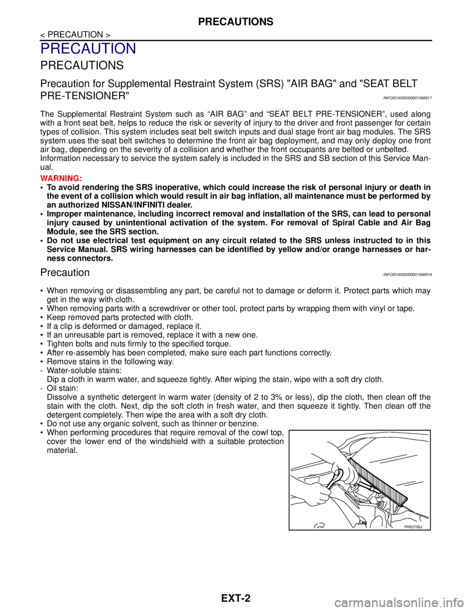
When performing procedures that require removal of the cowl top,
cover the lower end of the windshield with a suitable protection
material.
PIIB3706J
Page 3161 of 5883

FL-1
ENGINE
C
D
E
F
G
H
I
J
K
L
M
SECTION FL
A
FL
N
O
P
CONTENTS
FUEL SYSTEM
PRECAUTION ...............................................2
PRECAUTIONS ...................................................2
Precaution for Supplemental Restraint System
(SRS) "AIR BAG" and "SEAT BELT PRE-TEN-
SIONER" ...................................................................
2
PREPARATION ............................................3
PREPARATION ...................................................3
Special Service Tool .................................................3
ON-VEHICLE MAINTENANCE .....................4
FUEL SYSTEM ....................................................4
Checking Fuel Line ...................................................4
General Precaution ...................................................4
ON-VEHICLE REPAIR ..................................5
FUEL LEVEL SENSOR UNIT, FUEL FILTER
AND FUEL PUMP ASSEMBLY ..........................
5
HR16DE, HR18DE ...................................................5
Exploded View ..........................................................5
Removal and Installation ..........................................5
K9K ...........................................................................8
Exploded View ..........................................................8
Removal and Installation ..........................................8
FUEL TANK ......................................................10
HR16DE, HR18DE ..................................................10
Exploded View .........................................................10
Removal and Installation .........................................10
K9K ..........................................................................13
Exploded View .........................................................13
Removal and Installation .........................................13
SERVICE DATA AND SPECIFICATIONS
(SDS) ............................................................
16
SERVICE DATA AND SPECIFICATIONS
(SDS) .................................................................
16
Standard and Limit ..................................................16