2007 NISSAN TIIDA ecu active
[x] Cancel search: ecu activePage 2581 of 5883
![NISSAN TIIDA 2007 Service Repair Manual EC-1232
< ECU DIAGNOSIS >[K9K]
ECM
*: Just at start time. After 1 minute, EGR volume control valve will close and flow start increase.
ENGINE COOLING SUB FUNCTION
Test Condition: Engine Stopped and Ig](/manual-img/5/57395/w960_57395-2580.png "NISSAN TIIDA 2007 Service Repair Manual EC-1232
< ECU DIAGNOSIS >[K9K]
ECM
*: Just at start time. After 1 minute, EGR volume control valve will close and flow start increase.
ENGINE COOLING SUB FUNCTION
Test Condition: Engine Stopped and Ig")
EC-1232
< ECU DIAGNOSIS >[K9K]
ECM
*: Just at start time. After 1 minute, EGR volume control valve will close and flow start increase.
ENGINE COOLING SUB FUNCTION
Test Condition: Engine Stopped and Ignition Switch ON
Test Condition: Engine at Idle
COLD LOOP SUB FUNCTION
Test Condition: Engine Stopped and Ignition Switch ON
5 Intake air pressure ATOMOS PRESS700 mbar < ATOMOS PRESS <
1100 mbar
Indicates the ambient barometric
pressure in mbar. The sensor is
incorporated in the ECM.In the event of a malfunction, per-
form the trouble diagnosis for DTC
P2226 BARO SENSOR.
6 Fuel rail pressureRAIL PRESSUREIndicates the theoretical pressure
value for optimum engine opera-
tion.In the event of a malfunction, per-
form the trouble diagnosis for DTC
P0190 and P1089 FRP SENSOR.
RAIL PRES SET RAIL PRES SET = 0 bar.
7Air flow AIR FLOW200* mg/st < AIR FLOW < 350
mg/st
Air flow measured by the ECM.NONE
8 EGR EGR POS SE VO540 mV < EGR POS SE VO <
4490 mVIn the event of a malfunction, per-
form the trouble diagnosis for DTC
P0409 EGR VOLUME CONTROL
VALVE CONTROL POSITION
SENSOR.
9 Intake air pressure INLET PRESS - NONE
10Accelerator pedal
positionACCEL/PDL POS0% = ACCEL/PDL POS < 100%
Indicates the percentage of the
pedal position between no load
and full load positionIn the event of a malfunction, per-
form the trouble diagnosis for APP
SENSOR (DTC P0225, and P2120)
and SENSOR POWER SUPPLY
(DTC P0641 and P0651). Order Function Parameter Display and notes Trouble diagnosis
Order Function Parameter Display and notes Trouble diagnosis
1 Fan speed request*FAN ASSEMBLY INACTIVE
NONE. FAN UNIT LOW -
FAN UNIT HIGH -
2 Engine coolant tem-
peratureWATER TEMPClose to ambient temperature
(cold engine).
Indicates the engine coolant tem-
perature in °C. In the event of a malfunction, per-
form the trouble diagnosis for DTC
P0115 ECT SENSOR.
COOLAN TMP SEN V0.1V < COOLAN TMP SEN V <
4.9V
Order Function Parameter Display and notes Trouble diagnosis
1 Fan speed request*FAN ASSEMBLY INACTIVE
NONE. FAN UNIT LOW -
FAN UNIT HIGH -
2 Engine coolant tem-
peratureWATER TEMPIndicates the engine coolant
temperature in °C. In the event of a malfunction, per-
form the trouble diagnosis for DTC
P0115 ECT SENSOR.
COOLAN TMP SEN V0.1V < COOLAN TMP SEN V <
4.9V
Page 2582 of 5883
![NISSAN TIIDA 2007 Service Repair Manual ECM
EC-1233
< ECU DIAGNOSIS >[K9K]
C
D
E
F
G
H
I
J
K
L
MA
EC
N
P O Test Condition: Engine at Idle
Order Function Parameter Display and notes Trouble diagnosis
1 Fan speed request*FAN ASSEMBLY INACTIVE](/manual-img/5/57395/w960_57395-2581.png "NISSAN TIIDA 2007 Service Repair Manual ECM
EC-1233
< ECU DIAGNOSIS >[K9K]
C
D
E
F
G
H
I
J
K
L
MA
EC
N
P O Test Condition: Engine at Idle
Order Function Parameter Display and notes Trouble diagnosis
1 Fan speed request*FAN ASSEMBLY INACTIVE")
ECM
EC-1233
< ECU DIAGNOSIS >[K9K]
C
D
E
F
G
H
I
J
K
L
MA
EC
N
P O Test Condition: Engine at Idle
Order Function Parameter Display and notes Trouble diagnosis
1 Fan speed request*FAN ASSEMBLY INACTIVE
NONE. FAN UNIT LOW -
FAN UNIT HIGH -
2Compressor
engagement requestDMND LNK COMPThe ECM requests the IPDM E/R
(via CAN communication line) to
start the compressor
ACTIVE: The CAN communica-
tion should not be suspected on
the Automatic Transmission,
IPDM E/R or Intelligent Key unit
or BCM system.
The Intelligent Key unit or BCM
should request the ECM to be
engaged.
The refrigerant pressure sensor
should not be suspected. Satis-
factory engine operating condi-
tions (engine coolant
temperature, engine load etc.).
INACTIVE: One of the above
conditions has not been met.NONE
3Fast idle speed re-
questACCEL IDL RQ INACTIVE NONE
4 Refrigerant pressureRFRGERNT PRSSIndicates the value in Bar for the
refrigerant fluid in the system.
Default value: 0 Bar.In the event of a malfunction, per-
form the trouble diagnosis for DTC
P0530 REFRUGERANT PRES-
SURE SENSOR.
RFRGERNT FLUID V 0.1V < RFRGERNT FLUID V <
4.8V
5Engine coolant tem-
peratureWATER TEMPClose to ambient temperature
(cold engine).
Indicates the engine coolant tem-
perature in °C.In the event of a malfunction, per-
form the trouble diagnosis for DTC
P0115 ECT SENSOR.
6 Vehicle speed VEHICLE SPEED0 km/h (mph)
Indicates the vehicle speed in km/h
(mph). This parameter is transmit-
ted by the “ABS actuator and elec-
tric unit (control unit)” or
combination meter via CAN com-
munication line.Perform the trouble diagnosis for
CAN communication line. Perform
the trouble diagnosis for “ABS ac-
tuator and electric unit (control
unit)” or combination meter.
Order Function Parameter Display and notes Trouble diagnosis
1 Fan speed request*FAN ASSEMBLY INACTIVE
NONE. FAN UNIT LOW -
FAN UNIT HIGH -
Page 2583 of 5883
![NISSAN TIIDA 2007 Service Repair Manual EC-1234
< ECU DIAGNOSIS >[K9K]
ECM
CRUISE CONTROL/SPEED LIMITER SUB FUNCTION
Test Condition: Engine Stopped and Ignition Switch ON
Test Condition: Engine at Idle
PROTECTION SUBFUNCTION
Test Condition:](/manual-img/5/57395/w960_57395-2582.png "NISSAN TIIDA 2007 Service Repair Manual EC-1234
< ECU DIAGNOSIS >[K9K]
ECM
CRUISE CONTROL/SPEED LIMITER SUB FUNCTION
Test Condition: Engine Stopped and Ignition Switch ON
Test Condition: Engine at Idle
PROTECTION SUBFUNCTION
Test Condition:")
EC-1234
< ECU DIAGNOSIS >[K9K]
ECM
CRUISE CONTROL/SPEED LIMITER SUB FUNCTION
Test Condition: Engine Stopped and Ignition Switch ON
Test Condition: Engine at Idle
PROTECTION SUBFUNCTION
Test Condition: Engine Stopped and Ignition Switch ON
2Compressor
engagement re-
questDMND LNK COMPThe ECM requests the IPDM E/R
(via CAN communication line) to
start the compressor
ACTIVE: The CAN communica-
tion should not be suspected on
the Automatic Transmission,
IPDM E/R or Intelligent Key unit
or BCM system.
The Intelligent Key unit or BCM
should request the ECM to be en-
gaged.
The refrigerant pressure sensor
should not be suspected. Satis-
factory engine operating condi-
tions (engine coolant
temperature, engine load etc.).
INACTIVE: One of the above
conditions has not been met.NONE
3Fast idle speed re-
questACCEL IDL RQINACTIVE
or
ACTIVE
(Air conditioning is operate)NONE
4Refrigerant pres-
sureRFRGERNT PRSSIndicates the value in Bar for the re-
frigerant fluid in the system.
Default value: 0 Bar.In the event of a malfunction, per-
form the trouble diagnosis for DTC
P0530 REFRUGERANT PRES-
SURE SENSOR.
RFRGERNT FLUID V 0.1V < RFRGERNT FLUID V< 4.8V
5Engine coolant
temperatureWATER TEMPIndicates the engine coolant tem-
perature in °C.In the event of a malfunction, per-
form the trouble diagnosis for DTC
P0115 ECT SENSOR.
6 Vehicle speed VEHICLE SPEED0 km/h (mph)
Indicates the vehicle speed in km/h
(mph). This parameter is transmit-
ted by the “ABS actuator and elec-
tric unit (control unit)” or
combination meter via CAN com-
munication line.Perform the trouble diagnosis for
CAN communication line. Perform
the trouble diagnosis for “ABS actu-
ator and electric unit (control unit)”
or combination meter. Order Function Parameter Display and notes Trouble diagnosis
Order Function Parameter Display and notes Trouble diagnosis
1Cruise control/speed
limiterCRS CN/S LMTR INACTIVEIn the event of a malfunction, per-
form the trouble diagnosis for DTC
P0575 ASCD STEERING SWITCH.
Order Function Parameter Display and notes Trouble diagnosis
1Cruise control/speed
limiterCRS CN/S LMTR INACTIVEIn the event of a malfunction, perform
the trouble diagnosis for DTC P0575
ASCD STEERING SWITCH.
Page 2584 of 5883
![NISSAN TIIDA 2007 Service Repair Manual ECM
EC-1235
< ECU DIAGNOSIS >[K9K]
C
D
E
F
G
H
I
J
K
L
MA
EC
N
P O Test Condition: Engine at Idle
Order Function Parameter Display and notes Trouble diagnosis
1 Immobilizer ENGINE IMMOBIIndicates the](/manual-img/5/57395/w960_57395-2583.png "NISSAN TIIDA 2007 Service Repair Manual ECM
EC-1235
< ECU DIAGNOSIS >[K9K]
C
D
E
F
G
H
I
J
K
L
MA
EC
N
P O Test Condition: Engine at Idle
Order Function Parameter Display and notes Trouble diagnosis
1 Immobilizer ENGINE IMMOBIIndicates the")
ECM
EC-1235
< ECU DIAGNOSIS >[K9K]
C
D
E
F
G
H
I
J
K
L
MA
EC
N
P O Test Condition: Engine at Idle
Order Function Parameter Display and notes Trouble diagnosis
1 Immobilizer ENGINE IMMOBIIndicates the status of the immo-
bilizer system.
INACTIVE: The ECM has rec-
ognized the immobilizer code
transmitted by the Intelligent
Key unit or BCM.
ACTIVE: The ECM does not
recognize the immobilizer code
transmitted by the Intelligent
Key unit or BCM.If ACTIVE, perform the trouble diag-
nosis for NATS.
2 Battery voltage BATTERY VOLTAGE12V < BATTERY VOLTAGE <
14.4VIn the event of a malfunction, perform
the trouble diagnosis for CHARGING
SYSTEM.
3 Code programmed CODE PROGRAMStates whether the immobilizer
code has been programmed by
the computer or not.
YES: Code programmed
NO: Code not programmed by
the ECM.If NO, replace ECM.
Order Function Parameter Display and notes Trouble diagnosis
1 Immobilizer ENGINE IMMOBIIndicates the status of the immobiliz-
er system.
INACTIVE: The ECM has recog-
nized the immobilizer code trans-
mitted by the Intelligent Key unit or
BCM.
ACTIVE: The ECM does not recog-
nize the immobilizer code transmit-
ted by the Intelligent Key unit or
BCM.If ACTIVE, perform the trouble di-
agnosis for NATS.
2 Battery voltage BATTERY VOLTAGE 13V < BATTERY VOLTAGE < 16VIn the event of a malfunction, per-
form the trouble diagnosis for
CHARGING SYSTEM.
3 Code programmed CODE PROGRAMStates whether the immobilizer code
has been programmed by the com-
puter or not.
YES: Code programmed
NO: Code not programmed by the
ECM.If NO, replace ECM.
Page 3027 of 5883

EXL-26
< FUNCTION DIAGNOSIS >
DIAGNOSIS SYSTEM (BCM)
DIAGNOSIS SYSTEM (BCM)
COMMON ITEM
COMMON ITEM : CONSULT-III Function (BCM - COMMON ITEM)INFOID:0000000001528970
APPLICATION ITEM
CONSULT-III performs the following functions via CAN communication with BCM.
BCM
BCM : CONSULT-III Function (BCM - BCM)INFOID:0000000001528971
WORK SUPPORT
HEADLAMP
HEADLAMP : CONSULT-III Function (BCM - HEAD LAMP)INFOID:0000000001528977
WORK SUPPORT
*: Initial setting
DATA MONITOR
Diagnosis mode Function Description
WORK SUPPORT Changes the setting for each system function.
SELF-DIAG RESULTS Displays the diagnosis results judged by BCM. Refer to BCS-54, "
DTCIndex".
CAN DIAG SUPPORT MNTR Monitors the reception status of CAN communication viewed from BCM.
DATA MONITOR The BCM input/output signals are displayed.
ACTIVE TEST The signals used to activate each device are forcibly supplied from BCM.
ECU IDENTIFICATION The BCM part number is displayed.
CONFIGURATION Enables to read and save the vehicle specification.
Enables to write the vehicle specification when replacing BCM.
Item Description
RESET SETTING VALUE Return a value set with WORK SUPPORT of each system to a default value in factory shipment.
Work item Setting Description
BATTERY SAVER SETON*
Battery saver mode can be changed.
OFF
Monitor item
[Unit]Description
IGN ON SW [ON/OFF] Ignition switch (ON) status judged from IGN signal (ignition power supply)
HI BEAM SW [ON/OFF]
Each switch status that BCM judges from the combination switch reading function H/L SW POS [ON/OFF]
LIGHT SW 1ST [ON/OFF]
PASSING SW [ON/OFF]
AUTO LIGHT SW [ON/OFF]
FR FOG SW [ON/OFF]
RR FOG SW [ON/OFF]
DOOR SW-DR [ON/OFF] The switch status input from front door switch (driver side)
ENGINE STATUS The engine status received from ECM with CAN communication
Page 3257 of 5883
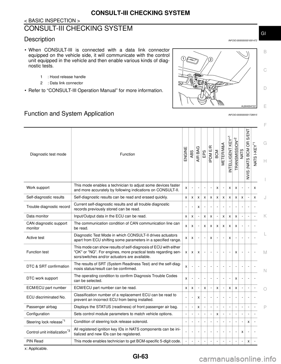
CONSULT-III CHECKING SYSTEM
GI-63
< BASIC INSPECTION >
C
D
E
F
G
H
I
J
K
L
MB
GI
N
O
PCONSULT-III CHECKING SYSTEM
DescriptionINFOID:0000000001691472
When CONSULT-III is connected with a data link connector
equipped on the vehicle side, it will communicate with the control
unit equipped in the vehicle and then enable various kinds of diag-
nostic tests.
Refer to “CONSULT-III Operation Manual” for more information.
Function and System ApplicationINFOID:0000000001728915
x: Applicable.1 : Hood release handle
2 : Data link connector
ALBIA0047ZZ
Diagnostic test mode Function
ENGINE
ABS
AIR BAG
EPS
IPDM E/R
BCM
METER/M&A
INTELLIGENT KEY*
1
TRANSMISSION*
2
NATS
NVIS (NATS BCM OR S/ENT
NATS I-KEY
*1
Work supportThis mode enables a technician to adjust some devices faster
and more accurately by following indications on CONSULT-II.x----x-xx--x
Self-diagnostic results Self-diagnostic results can be read and erased quickly. xxxxxxxxxx - x
Trouble diagnostic recordCurrent self-diagnostic results and all trouble diagnostic
records previously stored can be read.--x---------
Data monitor Input/Output data in the ECU can be read. x x - x x - x x x - - -
CAN diagnostic support
monitorThe communication condition of CAN communication line can
be read.xx - xxxxxx - - -
Active testDiagnostic Test Mode in which CONSULT-II drives actuators
apart from ECU shifting some parameters in a specified range.xx--x--x----
Function testThis mode can show results of self-diagnosis of ECU with either
"OK" or "NG". For engines, more practical tests regarding sen-
sors/switches and/or actuators are available.xxx-----x---
DTC & SRT confirmationThe results of SRT (System Readiness Test) and the self-diag-
nosis status/result can be confirmed.x-----------
DTC work supportThe operating condition to confirm Diagnosis Trouble Codes
can be selected.x-------x---
ECM/ECU part number ECM/ECU part number can be read. x x - x - x - x x - - -
ECU discriminated No.Classification number of a replacement ECU can be read to
prevent an incorrect ECU from being installed.--x---------
Passenger airbag Displays the STATUS (readiness) of front passenger air bag. --x---------
Configuration Sets control module parameters to match vehicle options. -----x------
Steering lock release
*1Condition of steering lock release solenoid. ----------x-
Control unit initialization
*3All registered ignition key IDs in NATS components can be ini-
tialized and new IDs can be registered.---------x--
PIN Read This mode enables technician to get BCM-specific 5-digit code.----------x-
Page 3348 of 5883
![NISSAN TIIDA 2007 Service Repair Manual DIAGNOSIS SYSTEM (BCM)
HAC-15
< FUNCTION DIAGNOSIS >[MANUAL AIR CONDITIONER]
C
D
E
F
G
H
J
K
L
MA
B
HAC
N
O
P
DIAGNOSIS SYSTEM (BCM)
CONSULT-III Function (BCM)INFOID:0000000001203060
CONSULT-III can d](/manual-img/5/57395/w960_57395-3347.png "NISSAN TIIDA 2007 Service Repair Manual DIAGNOSIS SYSTEM (BCM)
HAC-15
< FUNCTION DIAGNOSIS >[MANUAL AIR CONDITIONER]
C
D
E
F
G
H
J
K
L
MA
B
HAC
N
O
P
DIAGNOSIS SYSTEM (BCM)
CONSULT-III Function (BCM)INFOID:0000000001203060
CONSULT-III can d")
DIAGNOSIS SYSTEM (BCM)
HAC-15
< FUNCTION DIAGNOSIS >[MANUAL AIR CONDITIONER]
C
D
E
F
G
H
J
K
L
MA
B
HAC
N
O
P
DIAGNOSIS SYSTEM (BCM)
CONSULT-III Function (BCM)INFOID:0000000001203060
CONSULT-III can display each diagnostic item using the diagnostic test modes shown following.
DATA MONITOR
Display Item List
BCM diagnostic
test itemDiagnostic mode Description
Inspection by partWORK SUPPORTSupports inspections and adjustments. Commands are transmitted to the BCM for
setting the status suitable for required operation, input/output signals are received
from the BCM and received data is displayed.
DATA MONITOR Displays BCM input/output data in real time.
ACTIVE TEST Operation of electrical loads can be checked by sending drive signal to them.
SELF-DIAG RESULTS Displays BCM self-diagnosis results.
CAN DIAG SUPPORT MNTR The result of transmit/receive diagnosis of CAN communication can be read.
ECU PART NUMBER BCM part number can be read.
CONFIGURATION Performs BCM configuration read/write functions.
Monitor item name
“operation or unit”Contents
IGN ON SW “ON/OFF”Displays “IGN Position (ON)/OFF, ACC Position (OFF)” status as judged from ignition switch signal
through the CAN communication.
FAN ON SIG “ON/OFF”Displays “FAN (ON)/FAN (OFF)” status as judged from blower fan motor switch signal through CAN
communication.
AIR COND SW “ON/OFF”Displays “COMP (ON)/COMP (OFF)” status as judged from air conditioner switch signal through the
CAN communication.
Page 3430 of 5883
![NISSAN TIIDA 2007 Service Repair Manual DIAGNOSIS SYSTEM (BCM)
HAC-97
< FUNCTION DIAGNOSIS >[AUTO AIR CONDITIONER (W/O NAVI)]
C
D
E
F
G
H
J
K
L
MA
B
HAC
N
O
P
DIAGNOSIS SYSTEM (BCM)
CONSULT-III Function (BCM)INFOID:0000000001547400
CONSULT-](/manual-img/5/57395/w960_57395-3429.png "NISSAN TIIDA 2007 Service Repair Manual DIAGNOSIS SYSTEM (BCM)
HAC-97
< FUNCTION DIAGNOSIS >[AUTO AIR CONDITIONER (W/O NAVI)]
C
D
E
F
G
H
J
K
L
MA
B
HAC
N
O
P
DIAGNOSIS SYSTEM (BCM)
CONSULT-III Function (BCM)INFOID:0000000001547400
CONSULT-")
DIAGNOSIS SYSTEM (BCM)
HAC-97
< FUNCTION DIAGNOSIS >[AUTO AIR CONDITIONER (W/O NAVI)]
C
D
E
F
G
H
J
K
L
MA
B
HAC
N
O
P
DIAGNOSIS SYSTEM (BCM)
CONSULT-III Function (BCM)INFOID:0000000001547400
CONSULT-III can display each diagnostic item using the diagnostic test modes shown following.
DATA MONITOR
Display Item List
BCM diagnostic
test itemDiagnostic mode Description
Inspection by partWORK SUPPORTSupports inspections and adjustments. Commands are transmitted to the BCM for
setting the status suitable for required operation, input/output signals are received
from the BCM and received data is displayed.
DATA MONITOR Displays BCM input/output data in real time.
ACTIVE TEST Operation of electrical loads can be checked by sending drive signal to them.
SELF-DIAG RESULTS Displays BCM self-diagnosis results.
CAN DIAG SUPPORT MNTR The result of transmit/receive diagnosis of CAN communication can be read.
ECU PART NUMBER BCM part number can be read.
CONFIGURATION Performs BCM configuration read/write functions.
Monitor item name “operation or
unit”Contents
IGN ON SW “ON/OFF” Displays “IGN Position (ON)/OFF, ACC Position (OFF)” status as judged from ignition switch signal.
FAN ON SIG “ON/OFF” Displays “FAN (ON)/FAN (OFF)” status as judged from blower motor switch signal.
COMP ON SIG “ON/OFF” Displays “COMP (ON)/COMP (OFF)” status as judged from air conditioner switch signal.