2007 NISSAN TIIDA ecu active
[x] Cancel search: ecu activePage 3545 of 5883
![NISSAN TIIDA 2007 Service Repair Manual HAC-212
< FUNCTION DIAGNOSIS >[AUTO AIR CONDITIONER (W/NAVI)]
DIAGNOSIS SYSTEM (BCM)
DIAGNOSIS SYSTEM (BCM)
CONSULT-III Function (BCM)INFOID:0000000001547320
CONSULT-III can display each diagnostic it](/manual-img/5/57395/w960_57395-3544.png "NISSAN TIIDA 2007 Service Repair Manual HAC-212
< FUNCTION DIAGNOSIS >[AUTO AIR CONDITIONER (W/NAVI)]
DIAGNOSIS SYSTEM (BCM)
DIAGNOSIS SYSTEM (BCM)
CONSULT-III Function (BCM)INFOID:0000000001547320
CONSULT-III can display each diagnostic it")
HAC-212
< FUNCTION DIAGNOSIS >[AUTO AIR CONDITIONER (W/NAVI)]
DIAGNOSIS SYSTEM (BCM)
DIAGNOSIS SYSTEM (BCM)
CONSULT-III Function (BCM)INFOID:0000000001547320
CONSULT-III can display each diagnostic item using the diagnostic test modes shown following.
DATA MONITOR
Display Item List
BCM diagnostic
test itemDiagnostic mode Description
Inspection by partWORK SUPPORTSupports inspections and adjustments. Commands are transmitted to the BCM for
setting the status suitable for required operation, input/output signals are received
from the BCM and received data is displayed.
DATA MONITOR Displays BCM input/output data in real time.
ACTIVE TEST Operation of electrical loads can be checked by sending drive signal to them.
SELF-DIAG RESULTS Displays BCM self-diagnosis results.
CAN DIAG SUPPORT MNTR The result of transmit/receive diagnosis of CAN communication can be read.
ECU PART NUMBER BCM part number can be read.
CONFIGURATION Performs BCM configuration read/write functions.
Monitor item name “operation or
unit”Contents
IGN ON SW “ON/OFF”Displays “IGN Position (ON)/OFF, ACC Position (OFF)” status as judged from ignition switch signal
through the CAN communication.
FAN ON SIG “ON/OFF”Displays “FAN (ON)/FAN (OFF)” status as judged from blower motor switch signal through CAN com-
munication.
AIR COND SW “ON/OFF”Displays “COMP (ON)/COMP (OFF)” status as judged from air conditioner switch signal through the
CAN communication.
Page 3661 of 5883
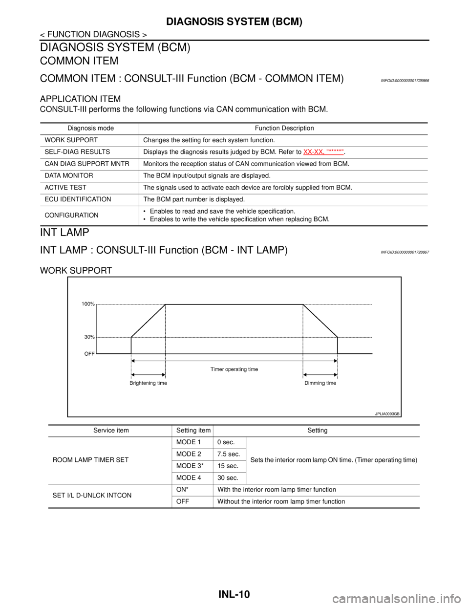
INL-10
< FUNCTION DIAGNOSIS >
DIAGNOSIS SYSTEM (BCM)
DIAGNOSIS SYSTEM (BCM)
COMMON ITEM
COMMON ITEM : CONSULT-III Function (BCM - COMMON ITEM)INFOID:0000000001728866
APPLICATION ITEM
CONSULT-III performs the following functions via CAN communication with BCM.
INT LAMP
INT LAMP : CONSULT-III Function (BCM - INT LAMP)INFOID:0000000001728867
WORK SUPPORT
Diagnosis mode Function Description
WORK SUPPORT Changes the setting for each system function.
SELF-DIAG RESULTS Displays the diagnosis results judged by BCM. Refer to XX-XX, "*****"
.
CAN DIAG SUPPORT MNTR Monitors the reception status of CAN communication viewed from BCM.
DATA MONITOR The BCM input/output signals are displayed.
ACTIVE TEST The signals used to activate each device are forcibly supplied from BCM.
ECU IDENTIFICATION The BCM part number is displayed.
CONFIGURATION Enables to read and save the vehicle specification.
Enables to write the vehicle specification when replacing BCM.
JPLIA0093GB
Service item Setting item Setting
ROOM LAMP TIMER SETMODE 1 0 sec.
Sets the interior room lamp ON time. (Timer operating time) MODE 2 7.5 sec.
MODE 3* 15 sec.
MODE 4 30 sec.
SET I/L D-UNLCK INTCONON* With the interior room lamp timer function
OFF Without the interior room lamp timer function
Page 4385 of 5883

MWI-78
< ECU DIAGNOSIS >
IPDM E/R (INTELLIGENT POWER DISTRIBUTION MODULE ENGINE ROOM)
Te r m i n a lWire
colorSignal nameSignal
input/
outputMeasuring condition
Reference value
(Approx.) Ignition
switchOperation or condition
1 R Battery power supply Input OFF — Battery voltage
2 G Battery power supply Input OFF — Battery voltage
3 Y ECM Relay Output —Ignition switch ON or START Battery voltage
Ignition switch OFF or ACC 0V
4 G ECM relay Output —Ignition switch ON or START Battery voltage
Ignition switch OFF or ACC 0V
6GRDaytime light relay
controlInput ON Daytime light system active. Less than battery voltage
Daytime light system inactive. Battery voltage
7 G ECM relay control Input —Ignition switch ON or START 0V
Ignition switch OFF or ACC Battery voltage
8GThrottle control motor
relayOutput —Ignition switch ON or START Battery voltage
Ignition switch OFF or ACC 0V
11 W A/C compressor OutputON or
STARTA/C switch ON or defrost A/C
switchBattery voltage
A/C switch OFF or defrost A/C
switch0V
12 OIgnition switch sup-
plied powerInput —OFF or ACC 0V
ON or START Battery voltage
14BR
(M/T)
R
(A/T)Fuse 49 Output —Ignition switch ON or START Battery voltage
Ignition switch OFF or ACC 0V
15 V Fuse 50 Output —Ignition switch ON or START Battery voltage
Ignition switch OFF or ACC 0V
16 SB Fuse 51 Output —Ignition switch ON or START Battery voltage
Ignition switch OFF or ACC 0V
19 R Starter motor Output START — Battery voltage
20L
(with
A/C)
LG
(with-
out A/
C)Cooling fan relay-1 Output —Conditions correct for cooling
fan low operation.Battery voltage
Conditions not correct for
cooling fan low operation.0V
21 WIgnition switch START
signalInput START — Battery voltage
22 G Battery power supply Input — — Battery voltage
23 L Cooling fan relay-2 Input —Conditions correct for cooling
fan high operationBattery voltage
Conditions not correct for
cooling fan high operation0V
24 Y Cooling fan relay-3 Output —Conditions correct for cooling
fan high operationBattery voltage
Conditions not correct for
cooling fan high operation0V
27 BR
Tail lamp relay (park-
ing lamps)Output — Lighting switch in 2nd position Battery voltage
Page 4392 of 5883

MWI
IPDM E/R (INTELLIGENT POWER DISTRIBUTION MODULE ENGINE ROOM)
MWI-85
< ECU DIAGNOSIS >
C
D
E
F
G
H
I
J
K
L
MB A
O
P If No CAN Communication Is Available With BCM
IGNITION RELAY MALFUNCTION DETECTION FUNCTION
IPDM E/R monitors the voltage at the contact circuit and excitation coil circuit of the ignition relay inside it.
IPDM E/R judges the ignition relay error if the voltage differs between the contact circuit and the excitation
coil circuit.
If the ignition relay cannot turn OFF due to contact seizure, it activates the tail lamp relay for 10 minutes to
alert the user to the ignition relay malfunction when the ignition switch is turned OFF.
NOTE:
The tail lamp turns OFF when the ignition switch is turned ON.
FRONT WIPER CONTROL
IPDM E/R detects front wiper stop position by a front wiper auto stop signal.
When a front wiper auto stop signal is in the conditions listed below, IPDM E/R stops power supply to wiper
after repeating a front wiper 10 second activation and 20 second stop five times.
NOTE:
This operation status can be confirmed on the IPDM E/R “DATA MONITOR” that displays “Block” for the item
“WIP PROT” while the wiper is stopped.
STARTER MOTOR PROTECTION FUNCTION
IPDM E/R turns OFF the starter control relay to protect the starter motor when the starter control relay remains
active for 90 seconds.
Control part Fail-safe in operation
Cooling fan Turns ON the cooling fan relay when the ignition switch is turned ON
Turns OFF the cooling fan relay when the ignition switch is turned OFF
Control part Fail-safe in operation
Headlamp Turns ON the headlamp low relay when the ignition switch is turned ON
Turns OFF the headlamp low relay when the ignition switch is turned OFF
Headlamp high relay OFF
Parking lamps
License plate lamps
Tail lamps Turns ON the tail lamp relay when the ignition switch is turned ON
Turns OFF the tail lamp relay when the ignition switch is turned OFF
Front wiper The status just before activation of fail-safe control is maintained until the ignition
switch is turned OFF while the front wiper is operating at LO or HI speed.
The wiper is operated at LO speed until the ignition switch is turned OFF if the fail-
safe control is activated while the front wiper is set in the INT mode and the front wiper
motor is operating.
Rear window defogger Rear window defogger relay OFF
A/C compressor A/C relay OFF
Front fog lamps Front fog lamp relay OFF
Ignition switch Ignition relay Tail lamp relay
ON ON —
OFF OFF —
Ignition switch Front wiper switch Auto stop signal
ONOFFFront wiper stop position signal cannot be
input 10 seconds.
ON The signal does not change for 10 seconds.
Page 4427 of 5883
![NISSAN TIIDA 2007 Service Repair Manual PCS
DIAGNOSIS SYSTEM (IPDM E/R)
PCS-13
< FUNCTION DIAGNOSIS >[IPDM E/R]
C
D
E
F
G
H
I
J
K
L B A
O
P N
CONSULT - III Function (IPDM E/R)INFOID:0000000001697590
APPLICATION ITEM
CONSULT-III performs the](/manual-img/5/57395/w960_57395-4426.png "NISSAN TIIDA 2007 Service Repair Manual PCS
DIAGNOSIS SYSTEM (IPDM E/R)
PCS-13
< FUNCTION DIAGNOSIS >[IPDM E/R]
C
D
E
F
G
H
I
J
K
L B A
O
P N
CONSULT - III Function (IPDM E/R)INFOID:0000000001697590
APPLICATION ITEM
CONSULT-III performs the")
PCS
DIAGNOSIS SYSTEM (IPDM E/R)
PCS-13
< FUNCTION DIAGNOSIS >[IPDM E/R]
C
D
E
F
G
H
I
J
K
L B A
O
P N
CONSULT - III Function (IPDM E/R)INFOID:0000000001697590
APPLICATION ITEM
CONSULT-III performs the following functions via CAN communication with IPDM E/R.
SELF DIAGNOSTIC
Refer to PCS-28, "DTCIndex".
DATA MONITOR
Monitor item
Diagnosis mode Description
ECU Identification Allows confirmation of IPDM E/R part number.
Self Diagnostic Result Displays the diagnosis results judged by IPDM E/R.
Data Monitor Displays the real-time input/output data from IPDM E/R input/output data.
Active Test IPDM E/R can provide a drive signal to electronic components to check their operations.
CAN Diag Support Monitor The results of transmit/receive diagnosis of CAN communication can be read.
Monitor Item
[Unit]MAIN SIG-
NALSDescription
MOTOR FAN REQ
[1/2/3/4]×Displays the status of the cooling fan speed request signal received from ECM via
CAN communication.
A/C COMP REQ
[OFF/ON]×Displays the status of the A/C request signal received from AV control unit via
CAN communication.
TAIL&CLR REQ
[OFF/ON]×Displays the status of the position light request signal received from BCM via CAN
communication.
HL LO REQ
[OFF/ON]×Displays the status of the low beam request signal received from BCM via CAN
communication.
HL HI REQ
[OFF/ON]×Displays the status of the high beam request signal received from BCM via CAN
communication.
FR FOG REQ
[OFF/ON]×Displays the status of the front fog lamp request signal received from BCM via
CAN communication.
HL WASHER REQ
[OFF/ON]NOTE:
This item is displayed, but cannot be monitored.
FR WIP REQ
[STOP/1LOW/LOW/HI]×Displays the status of the front wiper request signal received from BCM via CAN
communication.
WIP AUTO STOP
[STOP P/ACT P]×Displays the status of the front wiper auto stop signal judged by IPDM E/R.
WIP PROT
[OFF/Block]×Displays the status of the front wiper fail-safe operation judged by IPDM E/R.
ST RLY REQ
[OFF/ON]Displays the status of the starter request signal received from ECM via CAN com-
munication.
IGN RLY
[OFF/ON]×Displays the status of the ignition relay judged by IPDM E/R.
RR DEF REQ
[OFF/ON]×Displays the status of the rear defogger request signal received from AV control
unit via CAN communication.
OIL P SW
[OPEN/CLOSE]Displays the status of the oil pressure switch judged by IPDM E/R.
DTRL REQ
[OFF]NOTE:
This item is displayed, but cannot be monitored.
HOOD SW
[OPEN/CLOSE]NOTE:
This item is displayed, but cannot be monitored.
Page 4434 of 5883
![NISSAN TIIDA 2007 Service Repair Manual PCS-20
< ECU DIAGNOSIS >[IPDM E/R]
IPDM E/R (INTELLIGENT POWER DISTRIBUTION MODULE ENGINE ROOM)
Te r m i n a lWire
colorSignal nameSignal
input/
outputMeasuring condition
Reference value
(Approx.) I](/manual-img/5/57395/w960_57395-4433.png "NISSAN TIIDA 2007 Service Repair Manual PCS-20
< ECU DIAGNOSIS >[IPDM E/R]
IPDM E/R (INTELLIGENT POWER DISTRIBUTION MODULE ENGINE ROOM)
Te r m i n a lWire
colorSignal nameSignal
input/
outputMeasuring condition
Reference value
(Approx.) I")
PCS-20
< ECU DIAGNOSIS >[IPDM E/R]
IPDM E/R (INTELLIGENT POWER DISTRIBUTION MODULE ENGINE ROOM)
Te r m i n a lWire
colorSignal nameSignal
input/
outputMeasuring condition
Reference value
(Approx.) Ignition
switchOperation or condition
1 R Battery power supply Input OFF — Battery voltage
2 G Battery power supply Input OFF — Battery voltage
3 Y ECM Relay Output —Ignition switch ON or START Battery voltage
Ignition switch OFF or ACC 0V
4 G ECM relay Output —Ignition switch ON or START Battery voltage
Ignition switch OFF or ACC 0V
6GRDaytime light relay
controlInput ON Daytime light system active. Less than battery voltage
Daytime light system inactive. Battery voltage
7 G ECM relay control Input —Ignition switch ON or START 0V
Ignition switch OFF or ACC Battery voltage
8GThrottle control motor
relayOutput —Ignition switch ON or START Battery voltage
Ignition switch OFF or ACC 0V
11 W A/C compressor OutputON or
STARTA/C switch ON or defrost A/C
switchBattery voltage
A/C switch OFF or defrost A/C
switch0V
12 OIgnition switch sup-
plied powerInput —OFF or ACC 0V
ON or START Battery voltage
14BR
(M/T)
R
(A/T)Fuse 49 Output —Ignition switch ON or START Battery voltage
Ignition switch OFF or ACC 0V
15 V Fuse 50 Output —Ignition switch ON or START Battery voltage
Ignition switch OFF or ACC 0V
16 SB Fuse 51 Output —Ignition switch ON or START Battery voltage
Ignition switch OFF or ACC 0V
19 R Starter motor Output START — Battery voltage
20L
(with
A/C)
LG
(with-
out A/
C)Cooling fan relay-1 Output —Conditions correct for cooling
fan low operation.Battery voltage
Conditions not correct for
cooling fan low operation.0V
21 WIgnition switch START
signalInput START — Battery voltage
22 G Battery power supply Input — — Battery voltage
23 L Cooling fan relay-2 Input —Conditions correct for cooling
fan high operationBattery voltage
Conditions not correct for
cooling fan high operation0V
24 Y Cooling fan relay-3 Output —Conditions correct for cooling
fan high operationBattery voltage
Conditions not correct for
cooling fan high operation0V
27 BR
Tail lamp relay (park-
ing lamps)Output — Lighting switch in 2nd position Battery voltage
Page 4441 of 5883
![NISSAN TIIDA 2007 Service Repair Manual PCS
IPDM E/R (INTELLIGENT POWER DISTRIBUTION MODULE ENGINE ROOM)
PCS-27
< ECU DIAGNOSIS >[IPDM E/R]
C
D
E
F
G
H
I
J
K
L B A
O
P N If No CAN Communication Is Available With BCM
IGNITION RELAY MALFUNCTI](/manual-img/5/57395/w960_57395-4440.png "NISSAN TIIDA 2007 Service Repair Manual PCS
IPDM E/R (INTELLIGENT POWER DISTRIBUTION MODULE ENGINE ROOM)
PCS-27
< ECU DIAGNOSIS >[IPDM E/R]
C
D
E
F
G
H
I
J
K
L B A
O
P N If No CAN Communication Is Available With BCM
IGNITION RELAY MALFUNCTI")
PCS
IPDM E/R (INTELLIGENT POWER DISTRIBUTION MODULE ENGINE ROOM)
PCS-27
< ECU DIAGNOSIS >[IPDM E/R]
C
D
E
F
G
H
I
J
K
L B A
O
P N If No CAN Communication Is Available With BCM
IGNITION RELAY MALFUNCTION DETECTION FUNCTION
IPDM E/R monitors the voltage at the contact circuit and excitation coil circuit of the ignition relay inside it.
IPDM E/R judges the ignition relay error if the voltage differs between the contact circuit and the excitation
coil circuit.
If the ignition relay cannot turn OFF due to contact seizure, it activates the tail lamp relay for 10 minutes to
alert the user to the ignition relay malfunction when the ignition switch is turned OFF.
NOTE:
The tail lamp turns OFF when the ignition switch is turned ON.
FRONT WIPER CONTROL
IPDM E/R detects front wiper stop position by a front wiper auto stop signal.
When a front wiper auto stop signal is in the conditions listed below, IPDM E/R stops power supply to wiper
after repeating a front wiper 10 second activation and 20 second stop five times.
NOTE:
This operation status can be confirmed on the IPDM E/R “DATA MONITOR” that displays “Block” for the item
“WIP PROT” while the wiper is stopped.
STARTER MOTOR PROTECTION FUNCTION
IPDM E/R turns OFF the starter control relay to protect the starter motor when the starter control relay remains
active for 90 seconds.
Control part Fail-safe in operation
Cooling fan Turns ON the cooling fan relay when the ignition switch is turned ON
Turns OFF the cooling fan relay when the ignition switch is turned OFF
Control part Fail-safe in operation
Headlamp Turns ON the headlamp low relay when the ignition switch is turned ON
Turns OFF the headlamp low relay when the ignition switch is turned OFF
Headlamp high relay OFF
Parking lamps
License plate lamps
Tail lamps Turns ON the tail lamp relay when the ignition switch is turned ON
Turns OFF the tail lamp relay when the ignition switch is turned OFF
Front wiper The status just before activation of fail-safe control is maintained until the ignition
switch is turned OFF while the front wiper is operating at LO or HI speed.
The wiper is operated at LO speed until the ignition switch is turned OFF if the fail-
safe control is activated while the front wiper is set in the INT mode and the front wiper
motor is operating.
Rear window defogger Rear window defogger relay OFF
A/C compressor A/C relay OFF
Front fog lamps Front fog lamp relay OFF
Ignition switch Ignition relay Tail lamp relay
ON ON —
OFF OFF —
Ignition switch Front wiper switch Auto stop signal
ONOFFFront wiper stop position signal cannot be
input 10 seconds.
ON The signal does not change for 10 seconds.
Page 4471 of 5883

PWC-10
< FUNCTION DIAGNOSIS >
DIAGNOSIS SYSTEM (BCM)
DIAGNOSIS SYSTEM (BCM)
COMMON ITEM
COMMON ITEM : CONSULT-III Function (BCM - COMMON ITEM)INFOID:0000000001696302
APPLICATION ITEM
CONSULT-III performs the following functions via CAN communication with BCM.
SYSTEM APPLICATION
BCM can perform the following functions for each system.
NOTE:
It can perform the diagnosis modes except the following for all sub system selection items.
RETAINED PWR
RETAINED PWR : CONSULT-III Function (BCM - RETAINED PWR)INFOID:0000000001696303
Data monitor
Diagnosis mode Function Description
WORK SUPPORT Changes the setting for each system function.
SELF-DIAG RESULTS Displays the diagnosis results judged by BCM. Refer to BCS-54, "
DTCIndex".
CAN DIAG SUPPORT MNTR Monitors the reception status of CAN communication viewed from BCM.
DATA MONITOR The BCM input/output signals are displayed.
ACTIVE TEST The signals used to activate each device are forcibly supplied from BCM.
ECU IDENTIFICATION The BCM part number is displayed.
CONFIGURATION This function is not used even though it is displayed.
System Sub system selection itemDiagnosis mode
WORK SUPPORT DATA MONITOR ACTIVE TEST
BCM BCM×
RAP system RETAINED PWR×
Monitor Item Description
DOOR SW-DR Indicates [ON/OFF] condition of front door switch LH.
DOOR SW-AS Indicates [ON/OFF] condition of front door switch RH.