2007 NISSAN TIIDA coolant level
[x] Cancel search: coolant levelPage 2729 of 5883

EM-82
< ON-VEHICLE REPAIR >[HR16DE]
CYLINDER HEAD
In this step, loosen bolts in reverse order of that indicated.
d. Tighten all bolts.
e. Turn all bolts 75 degrees clockwise (angle tightening).
CAUTION:
Check and confirm the tightening angle by using the angle
wrench [SST: KV10112100] (A) or protractor. Avoid judg-
ment by visual inspection without the tool.
f. Turn all bolts 75 degrees clockwise again (angle tightening).
3. Installation is in the reverse order of removal, for the remaining parts.
INSPECTION AFTER INSTALLATION
Inspection for Leaks
Before starting engine, check oil/fluid levels including engine coolant and engine oil. If less than required
quantity, fill to the specified level. Refer to MA-19, "
Fluids and Lubricants".
Use procedure below to check for fuel leakage.
- Turn ignition switch “ON” (with engine stopped). With fuel pressure applied to fuel piping, check for fuel leak-
age at connection points.
- Start engine. With engine speed increased, check again for fuel leakage at connection points.
Run engine to check for unusual noise and vibration.
Warm up engine thoroughly to make sure there is no leakage of fuel, exhaust gases, or any oil/fluids includ-
ing engine oil and engine coolant.
Bleed air from lines and hoses of applicable lines, such as in cooling system.
After cooling down engine, again check oil/fluid levels including engine oil and engine coolant. Refill to the
specified level, if necessary.
Summary of the inspection items:
*: Transmission/transaxle/CVT fluid, power steering fluid, brake fluid, etc.
Disassembly and AssemblyINFOID:0000000001381422
: 40.0 N·m (4.1 kg-m, 30 ft-lb)
PBIC3733E
Items Before starting engine Engine running After engine stopped
Engine coolant Level Leakage Level
Engine oil Level Leakage Level
Other oils and fluid* Level Leakage Level
Fuel Leakage Leakage Leakage
Exhaust gases — Leakage —
Page 2739 of 5883

EM-92
< REMOVAL AND INSTALLATION >[HR16DE]
ENGINE ASSEMBLY
4. Remove engine mounting insulator (RH) (1), engine mounting
bracket (RH) (2) and engine mounting stay (3).
5. Remove engine mounting through bolt-securing nut (A).
6. Carefully lower jack, or raise lift to remove the engine and the transaxle assembly.
CAUTION:
Make sure that no part interferes with the vehicle side.
Before and during this lifting, always check if any harnesses are left connected.
During the removal, always be careful to prevent the vehicle from falling off the lift due to
changes in the center of gravity.
If necessary, support the vehicle by setting jack or suitable tool at the rear.
Separation
1. Remove starter motor. Refer to STR-13, "Removal and Installation".
2. Lift with a hoist and separate the engine from the transaxle assembly. Refer to EM-89, "
Exploded View".
INSTALLATION
Installation is in the reverse order of removal.
Do not allow engine oil to get on engine mounting insulator. Be careful not to damage engine mounting insu-
lator.
Make sure that each mounting insulator is seated properly, and tighten mounting nuts and bolts.
Tighten engine mounting insulator (RH) bolts in the numerical
order shown.
InspectionINFOID:0000000001381426
INSPECTION AFTER INSTALLATION
Inspection for Leaks
Before starting engine, check oil/fluid levels including engine coolant and engine oil. If less than required
quantity, fill to the specified level. Refer to MA-19, "
Fluids and Lubricants".
Use procedure below to check for fuel leakage.
- Turn ignition switch “ON” (with engine stopped). With fuel pressure applied to fuel piping, check for fuel leak-
age at connection points.
- Start engine. With engine speed increased, check again for fuel leakage at connection points.
Run engine to check for unusual noise and vibration.
Warm up engine thoroughly to make sure there is no leakage of fuel, exhaust gases, or any oil/fluids includ-
ing engine oil and engine coolant.
Bleed air from lines and hoses of applicable lines, such as in cooling system.
After cooling down engine, again check oil/fluid levels including engine oil and engine coolant. Refill to the
specified level, if necessary.
4 : Engine mounting insulator (LH)
JPBIA0512ZZ
: Vehicle front
JPBIA0280ZZ
Page 2740 of 5883

ENGINE ASSEMBLY
EM-93
< REMOVAL AND INSTALLATION >[HR16DE]
C
D
E
F
G
H
I
J
K
L
MA
EM
N
P O
Summary of the inspection items:
*: Transmission/transaxle/CVT fluid, power steering fluid, brake fluid, etc.Items Before starting engine Engine running After engine stopped
Engine coolant Level Leakage Level
Engine oil Level Leakage Level
Other oils and fluid* Level Leakage Level
Fuel Leakage Leakage Leakage
Exhaust gases — Leakage —
Page 2803 of 5883

EM-156
< ON-VEHICLE REPAIR >[MR18DE]
INTAKE MANIFOLD
INTAKE MANIFOLD
ComponentINFOID:0000000001337785
Removal and InstallationINFOID:0000000001337786
REMOVAL
1. Remove engine cover (1).
2. Drain engine coolant. Refer to CO-35, "
Changing Engine Cool-
ant".
CAUTION:
Perform this step when engine is cold.
NOTE:
This step is unnecessary when putting plugs to water hoses (to
electronic throttle control actuator)
a. Disconnect water hoses from electronic throttle control actuator.
b. Remove electronic throttle control actuator.
CAUTION:
Handle carefully to avoid any shock to electronic throttle
control actuator.
Never disassemble.
3. Remove oil level gauge.
CAUTION:
Cover the oil level gauge guide openings to avoid entry of foreign materials.
1. PCV hose 2. Gasket 3. Intake manifold
4. Bracket 5. O-ring 6. EVAP canister purge volume control
solenoid valve
7. Water hose 8. Water hose 9. Electronic throttle control actuator
10. Gasket A. To water outlet
WBIA0771E
WBIA0845E
Page 2840 of 5883

CAMSHAFT
EM-193
< ON-VEHICLE REPAIR >[MR18DE]
C
D
E
F
G
H
I
J
K
L
MA
EM
N
P O
10. Install camshaft sprocket (EXH) (2).
NOTE:
Secure the hexagonal part (A) of camshaft (EXH) using wrench
to tighten bolt.
11. Install timing chain and related parts. Refer to EM-176
.
12. Inspect and adjust valve clearance. Refer to EM-148, "
Valve Clearance".
13. Installation of the remaining components is in the reverse order of removal.
INSPECTION AFTER INSTALLATION
The following are procedures for checking fluids leak, lubricates leak.
Before starting engine, check oil/fluid levels including engine coolant and engine oil. If less than required
quantity, fill to the specified level. Refer to GI-27, "
Recommended Chemical Products and Sealants".
Use procedure below to check for fuel leakage.
- Turn ignition switch “ON” (with engine stopped). With fuel pressure applied to fuel piping, check for fuel leak-
age at connection points.
- Start engine. With engine speed increased, check again for fuel leakage at connection points.
Run engine to check for unusual noise and vibration.
NOTE:
If hydraulic pressure inside timing chain tensioner drops after removal/installation, slack in the guide may
generate a pounding noise during and just after engine start. However, this is normal. Noise will stop after
hydraulic pressure rises.
Warm up engine thoroughly to make sure there is no leakage of fuel, or any oil/fluids including engine oil and
engine coolant.
Bleed air from lines and hoses of applicable lines, such as in cooling system.
After cooling down engine, again check oil/fluid levels including engine oil and engine coolant. Refill to the
specified level, if necessary.
Summary of the inspection items:
* Transmission/transaxle/CVT fluid, power steering fluid, brake fluid, etc.
Inspection of Camshaft Sprocket (INT) Oil Groove
CAUTION:
Perform this inspection only when DTC P0011 is detected in self-diagnostic results of CONSULT-III
and it is directed according to inspection procedure of EC section. Refer to EC-796, "
Diagnosis Pro-
cedure".
Check when engine is cold so as to prevent burns from the splashing engine oil.
1. Check engine oil level. Refer to LU-15, "
Inspection".
2. Perform the following procedure so as to prevent the engine from being unintentionally started while
checking.
a. Remove intake manifold. Refer to EM-156, "
Component".
b. Disconnect ignition coil and injector harness connectors.
3. Remove intake valve timing control solenoid valve. Refer to EM-176, "
Component".
1 : Camshaft sprocket (INT)
Camshaft sprocket
bolt (EXH): 88.2 N·m (9.0 kg-m, 65 ft-lb)
PBIC3454J
Item Before starting engine Engine running After engine stopped
Engine coolant Level Leakage Level
Engine oil Level Leakage Level
Other oils and fluid* Level Leakage Level
Fuel Leakage Leakage Leakage
Exhaust gases — Leakage —
Page 2857 of 5883

EM-210
< REMOVAL AND INSTALLATION >[MR18DE]
ENGINE ASSEMBLY
When installation directions are specified, install parts according to the directions. Refer to EM-207, "Com-
ponent".
Prior to installing the upper torque rod, apply a light coat of silicone
lubricant (A) to the washer facing side of the bushing inner tube as
shown.
NOTE:
Apply silicone lubricant (A) by dabbing the outward facing tube
surface with a sponge or suitable tool.
Do not apply excess lubricant.
Make sure that each mounting insulator is seated properly, and tighten nuts and bolts.
Tighten engine mounting insulator (RH) bolts in the numerical
order shown.
INSPECTION AFTER INSTALLATION
Inspection for Leaks
The following are procedures for checking fluids leak, lubricates leak and exhaust gases leak.
Before starting engine, check oil/fluid levels including engine coolant and engine oil. If less than required
quantity, fill to the specified level. Refer to LU-15, "
Inspection", CO-35, "Inspection".
Use procedure below to check for fuel leakage.
- Turn ignition switch “ON” (with engine stopped). With fuel pressure applied to fuel piping, check for fuel leak-
age at connection points.
- Start engine. With engine speed increased, check again for fuel leakage at connection points.
Run engine to check for unusual noise and vibration.
Warm up engine thoroughly to make sure there is no leakage of fuel, exhaust gases, or any oil/fluids includ-
ing engine oil and engine coolant.
Bleed air from lines and hoses of applicable lines, such as in cooling system.
After cooling down engine, again check oil/fluid levels including engine oil and engine coolant. Refill to the
specified level, if necessary.
Summary of the inspection items:
* Transmission/transaxle fluid, power steering fluid, brake fluid, etc.: Vehicle front
LBIA0470E
: Vehicle front
WBIA0785E
Item Before starting engine Engine running After engine stopped
Engine coolant Level Leakage Level
Engine oil Level Leakage Level
Other oils and fluid* Level Leakage Level
Fuel Leakage Leakage Leakage
Exhaust gases — Leakage —
Page 2951 of 5883

EM-304
< REMOVAL AND INSTALLATION >[K9K]
ENGINE ASSEMBLY
1. Install engine slingers (1) into front right of cylinder head and
engine slinger (2) into rear left of cylinder head.
2. Remove upper torque rod.
3. Use a manual lift table caddy (commercial service tool) or equiv-
alently rigid tool such as a jack or trestle. Securely support bot-
tom of engine and transaxle.
CAUTION:
Put a piece of wood or something similar at the supporting
surface to secure a stable condition.
4. Remove RH and LH engine mounting bolts.
5. Remove engine and transaxle assembly from vehicle downward
by carefully operating supporting tools.
CAUTION:
During the operation, make sure that no part interferes with body side.
Before and during this lifting, always check if any harnesses are left connected.
During the removal operation, always be careful to prevent vehicle from falling off the lift due to
changes in the center of gravity.
If necessary, support vehicle by setting a jack or equivalent tool at the rear.
Separation Work
CAUTION:
During the operation, secure the engine by placing a piece of wood under the engine oil pan and tran-
saxle and lift the engine using a suitable tool.
1. Remove starter motor.
2. Separate engine and transaxle.
3. Lift the engine with a suitable tool and separate the engine from the transaxle assembly. Refer to EM-302,
"Exploded View".
INSTALLATION
Installation is in the reverse order of removal.
Do not allow oil to get on mounting insulator. Be careful not to damage mounting insulator.
When installation directions are specified, install parts according to the direction marks on them referring to
exploded views.
Make sure that each mounting insulator is seated properly, and tighten mounting bolts and nuts.
InspectionINFOID:0000000001381506
INSPECTION AFTER INSTALLATION
Before starting engine check the levels of coolant, lubricants and oils. Fill to the specified level.
Before starting engine, bleed air from fuel piping. Refer to EM-287, "
Removal and Installation".
Run engine to check for unusual noise and vibration.
Warm up engine thoroughly to make sure there is no leakage of coolant, lubricants, oil, fuel and exhaust
gas.
Bleed air from passages in pipes and tubes of applicable lines.
MBIB9022E
Page 3082 of 5883
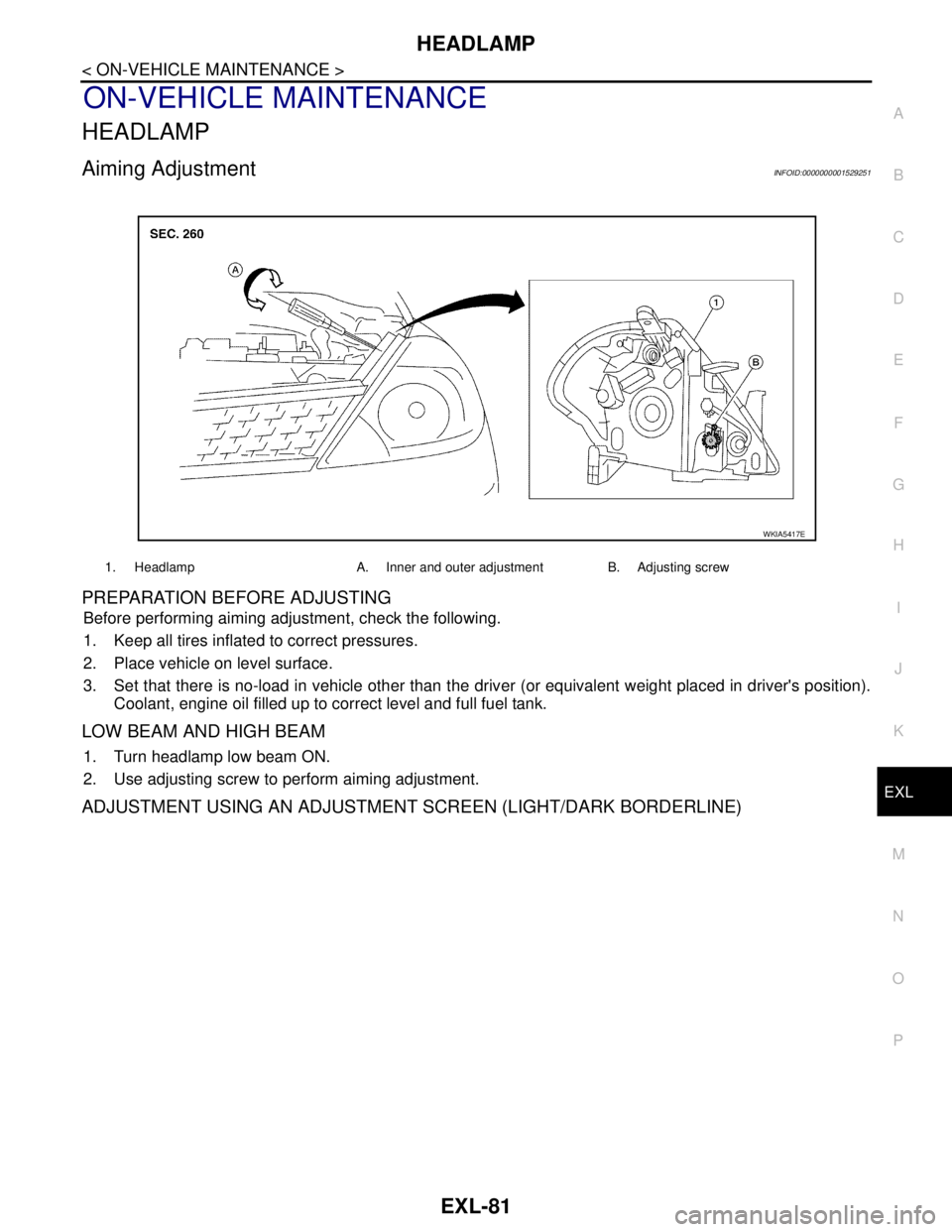
HEADLAMP
EXL-81
< ON-VEHICLE MAINTENANCE >
C
D
E
F
G
H
I
J
K
MA
B
EXL
N
O
P
ON-VEHICLE MAINTENANCE
HEADLAMP
Aiming AdjustmentINFOID:0000000001529251
PREPARATION BEFORE ADJUSTING
Before performing aiming adjustment, check the following.
1. Keep all tires inflated to correct pressures.
2. Place vehicle on level surface.
3. Set that there is no-load in vehicle other than the driver (or equivalent weight placed in driver's position).
Coolant, engine oil filled up to correct level and full fuel tank.
LOW BEAM AND HIGH BEAM
1. Turn headlamp low beam ON.
2. Use adjusting screw to perform aiming adjustment.
ADJUSTMENT USING AN ADJUSTMENT SCREEN (LIGHT/DARK BORDERLINE)
1. Headlamp A. Inner and outer adjustment B. Adjusting screw
WKIA5417E