2007 NISSAN TIIDA coolant level
[x] Cancel search: coolant levelPage 2396 of 5883
INSPECTION AND ADJUSTMENT
EC-1047
< BASIC INSPECTION >[K9K]
C
D
E
F
G
H
I
J
K
L
MA
EC
N
P O
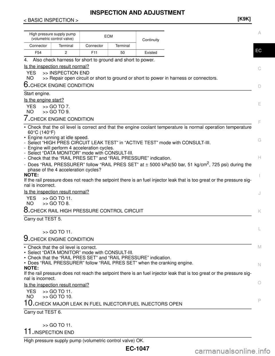
4. Also check harness for short to ground and short to power.
Is the inspection result normal?
YES >> INSPECTION END
NO >> Repair open circuit or short to ground or short to power in harness or connectors.
6.CHECK ENGINE CONDITION
Start engine.
Is the engine start?
YES >> GO TO 7.
NO >> GO TO 9.
7.CHECK ENGINE CONDITION
Check that the oil level is correct and that the engine coolant temperature is normal operation temperature
60°C (140°F)
Engine running at idle speed.
- Select “HIGH PRES CIRCUIT LEAK TEST” in “ACTIVE TEST” mode with CONSULT-III.
- Engine will perform 4 acceleration cycles.
- Select “DATA MONITOR” mode with CONSULT-III.
- Check that the “RAIL PRES SET” and “RAIL PRESSURE” indication.
- Does “RAIL PRESSURER” follow “RAIL PRES SET” at ± 5000 kPa(50 bar, 51 kg/cm
2, 725 psi) during the
phase of the 4 acceleration cycles?
NOTE:
If the rail pressure does not reach the setpoint there is an fuel injector leak that is too great or the pressure sig-
nal is incorrect.
Is the inspection result normal?
YES >> GO TO 11.
NO >> GO TO 8.
8.CHECK RAIL HIGH PRESSURE CONTROL CIRCUIT
Carry out TEST 5.
>> GO TO 11.
9.CHECK ENGINE CONDITION
Check that the oil level is correct.
Select “DATA MONITOR” mode with CONSULT-III.
Check that the “RAIL PRES SET” and “RAIL PRESSURE” indication.
Does “RAIL PRESSURER” follow “RAIL PRES SET” when the cranking engine.
NOTE:
If the rail pressure does not reach the setpoint there is an fuel injector leak that is too great or the pressure sig-
nal is incorrect.
Is the inspection result normal?
YES >> GO TO 11.
NO >> GO TO 10.
10.CHECK MAJOR LEAK IN FUEL INJECTOR/FUEL INJECTORS OPEN
Carry out TEST 6.
>> GO TO 11.
11 .INSPECTION END
High pressure supply pump (volumetric control valve) OK.
High pressure supply pump
(volumetric control valve)ECM
Continuity
Connector Terminal Connector Terminal
F54 2 F11 50 Existed
Page 2398 of 5883
INSPECTION AND ADJUSTMENT
EC-1049
< BASIC INSPECTION >[K9K]
C
D
E
F
G
H
I
J
K
L
MA
EC
N
P O
>> INSPECTION END
6.CHECK ENGINE CONDITION
Check that the oil level is correct and that the engine coolant temperature is normal operation tempera-
ture.60°C (140°F)
Engine running at idle speed.
- Select “HIGH PRES CIRCUIT LEAK TEST” in “ACTIVE TEST” mode with CONSULT-III.
- Engine will perform 4 acceleration cycles.
- Select “DATA MONITOR” mode with CONSULT-III.
- Check that the “RAIL PRES SET” and “RAIL PRESSURE” indication.
- Does “RAIL PRESSURE” follow “RAIL PRES SET” at during the phase of 4 acceleration cycles?
Is the inspection result normal?
YES >> GO TO 22.
NO >> GO TO 7.
7.CHECK ENGINE COOLANT TEMPERATURE AND FUEL TEMPERATURE
1. Select “DATA MONITOR” mode with CONSULT-III.
2. Check that the “FUEL TEMP” indication when operating at idle speed is between 60 - 80°C (140 - 176°F)
3. Check that the “WATER TEMP” indication is between 80 - 90°C (176 - 194°F)
NOTE:
When the fuel temperature is above 136°C (277°F), the maximum rail pressure is reduced to protect the
plastic pipes.
When the coolant temperature is above 100°C (212°F), the maximum rail pressure is reduced to protect the
engine.
Are the
“FUEL TEMP” and “WATER TEMP” within the reference value range?
YES >> GO TO 8.
NO >> Check the fuel pump temperature sensor (Refer to EC-1137, "
Component Inspection") or engine
coolant temperature sensor (Refer to EC-1133, "
Component Inspection").
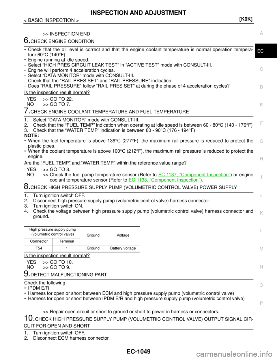
8.CHECK HIGH PRESSURE SUPPLY PUMP (VOLUMETRIC CONTROL VALVE) POWER SUPPLY
1. Turn ignition switch OFF.
2. Disconnect high pressure supply pump (volumetric control valve) harness connector.
3. Turn ignition switch ON.
4. Check the voltage between high pressure supply pump (volumetric control valve) harness connector and
ground.
Is the inspection result normal?
YES >> GO TO 10.
NO >> GO TO 9.
9.DETECT MALFUNCTIONING PART
Check the following.
IPDM E/R
Harness for open or short between ECM and high pressure supply pump (volumetric control valve)
Harness for open or short between IPDM E/R and high pressure supply pump (volumetric control valve)
>> Repair open circuit or short to ground or short to power in harness or connectors.
10.CHECK HIGH PRESSURE SUPPLY PUMP (VOLUMETRIC CONTROL VALVE) OUTPUT SIGNAL CIR-
CUIT FOR OPEN AND SHORT
1. Turn ignition switch OFF.
2. Disconnect ECM harness connector.
High pressure supply pump
(volumetric control valve)
Ground Voltage
Connector Terminal
F54 1 Ground Battery voltage
Page 2412 of 5883
FUEL INJECTION CONTROL
EC-1063
< FUNCTION DIAGNOSIS >[K9K]
C
D
E
F
G
H
I
J
K
L
MA
EC
N
P O
FUEL INJECTION CONTROL
System DescriptionINFOID:0000000001162530
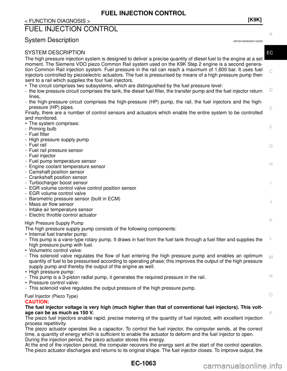
SYSTEM DESCRIPTION
The high pressure injection system is designed to deliver a precise quantity of diesel fuel to the engine at a set
moment. The Siemens VDO piezo Common Rail system used on the K9K Step 2 engine is a second genera-
tion Common Rail injection system. Fuel pressure in the rail can reach a maximum of 1,600 bar. It uses fuel
injectors controlled by piezoelectric actuators. The fuel is pressurised by means of a high pressure pump then
sent to a rail which supplies the four fuel injectors.
The circuit comprises two subsystems, which are distinguished by the fuel pressure level:
- the low pressure circuit comprises the tank, the diesel fuel filter, the transfer pump and the fuel injector return
lines,
- the high-pressure circuit comprises the high-pressure (HP) pump, the rail, the fuel injectors and the high-
pressure (HP) pipes.
Finally, there are a number of control sensors and actuators which enable the entire system to be controlled
and monitored.
The system comprises:
- Priming bulb
- Fuel filter
- High pressure supply pump
- Fuel rail
- Fuel rail pressure sensor
- Fuel injector
- Fuel pump temperature sensor
- Engine coolant temperature sensor
- Camshaft position sensor
- Crankshaft position sensor
- Turbocharger boost sensor
- EGR volume control valve control position sensor
- EGR volume control valve
- Barometric pressure sensor (built in ECM)
- Mass air flow sensor
- Intake air temperature sensor
- Electric throttle control actuator
High Pressure Supply Pump
The high pressure supply pump consists of the following components:
Internal fuel transfer pump:
- This pump is a vane-type rotary pump. It draws in fuel from the fuel tank through a fuel filter and supplies the
high pressure pump with fuel.
Volumetric control valve:
- This solenoid valve regulates the flow of fuel entering the high pressure pump and enables an optimum
quantity of fuel to be pressurised according to operating phase; this improves the output of the high pressure
supply pump and thereby the output of the engine as well.
High pressure pump:
- This pump is a 3-piston radial pump, it generates the required pressure in the rail.
Pressure control valve:
- This solenoid valve regulates the output pressure of the high pressure pump.
Fuel Injector (Piezo Type)
CAUTION:
The fuel injector voltage is very high (much higher than that of conventional fuel injectors). This volt-
age can be as much as 150 V.
The piezo fuel injectors enable rapid, precise metering of the quantity of fuel injected, with excellent injection
process repetitivity.
The piezo actuator operates like a capacitor. To control the fuel injector, the computer sends, at the correct
time, a quantity of energy which is sufficient to enable the actuator to deform and the fuel injector to open.
During the injection period, the piezo actuator stores this energy.
At the end of the injection period, the computer recovers the energy sent at the start of the control operation.
The piezo actuator discharges and returns to its original shape. The fuel injector closes. To improve output, the
Page 2608 of 5883
STARTING DIFFICULT WITH COLD ENGINE
EC-1259
< SYMPTOM DIAGNOSIS >[K9K]
C
D
E
F
G
H
I
J
K
L
MA
EC
N
P O
STARTING DIFFICULT WITH COLD ENGINE
DescriptionINFOID:0000000001162703
CHART 3: STARTING DIFFICULT WITH COLD ENGINE
Diagnosis ProcedureINFOID:0000000001162704
1.CHECK ENGINE OIL LEVEL
Is the engine oil level correct?
Ye s o r N o
Yes >> GO TO 2.
No >> Top up the oil.
2.CHECK ENGINE OIL
Check the grade of engine oil. Refer to LU-26, "
Inspection".
Is the inspection result normal?
YES >> GO TO 3.
NO >> Replace engine oil. Refer to LU-27, "
Refilling"
3.CHECK BATTERY
Check the battery. Refer to PG-6, "
Removal and Installation".
Is the inspection result normal?
YES >> GO TO 4.
NO >> Repair or replace battery. Refer to PG-6, "
Removal and Installation"
4.CHECK STARTER MOTOR
Check the starter motor. Refer to STR-35, "
Removal and Installation".
Is the inspection result normal?
YES >> GO TO 5.
NO >> Repair or replace starter motor. Refer to STR-35, "
Removal and Installation"
5.CHECK COMPONENT PART
Check the following.
Engine coolant temperature sensor. Refer to EC-1133, "
Component Inspection".
Fuel pump temperature sensor. Refer to EC-1137, "
Component Inspection".
Intake air temperature sensor. Refer to EC-1131, "
Component Inspection".
Is the inspection result normal?
YES >> GO TO 6.
NO >> Repair or replace.
6.CHECK GLOW SYSTEM
Check the glow system. Refer to EC-1156, "
Diagnosis Procedure".
Is the inspection result normal?
YES >> GO TO 7.
NO >> Repair or replace glow system. Refer to EM-279, "
Removal and Installation"
7.CHECK LOW PRESSURE CIRCUIT
Perform the TEST 1: LOW PRESSURE CIRCUIT CHECK. Refer to EC-1043, "
BASIC INSPECTION : Special
Repair Requirement (TEST 1: Low Pressure Fuel Supply System Check)".
>> GO TO 8.
8.CHECK INTERNAL FUEL TRANSFER PUMP
Perform the TEST 2: INTERNAL FUEL TRANSFER PUMP CHECK. Refer to EC-1044, "
BASIC INSPECTION
: Special Repair Requirement (TEST 2: Internal Fuel Transfer Pump Check)".
Page 2635 of 5883
EC-1286
< SYMPTOM DIAGNOSIS >[K9K]
ENGINE SMOKES WHEN STARTED
ENGINE SMOKES WHEN STARTED
DescriptionINFOID:0000000001162733
CHART 18: ENGINE SMOKES WHEN STARTED
Diagnosis ProcedureINFOID:0000000001162734
1.CHECK ENGINE OIL
Check the grade of engine oil. Refer to LU-26, "
Inspection".
Is the inspection result normal?
YES >> GO TO 2.
NO >> Replace engine oil. Refer to LU-27, "
Refilling"
2.CHECK ENGINE OIL LEVEL
Is the engine oil level correct?
Ye s o r N o
Ye s > > G O T O 3 .
No >> Top up the oil.
3.CHECK FUEL PUMP TEMPERATURE SENSOR
Check fuel pump temperature sensor. Refer to EC-1137, "
Component Inspection".
Is the inspection result normal?
Ye s > > G O T O 4 .
No >> Repair or replace.
4.CHECK ENGINE COOLANT TEMPERATURE SENSOR
Check engine coolant temperature sensor. Refer to EC-1133, "
Component Inspection".
Is the inspection result normal?
Ye s > > G O T O 5 .
No >> Repair or replace.
5.CHECK COOLING SYSTEM
Check the cooling system. Refer to CO-53, "
Troubleshooting Chart".
Is the inspection result normal?
YES >> GO TO 6.
NO >> Repair or replace.
6.CHECK HIGH PRESSURE SUPPLY PUMP (PRESSURE CONTROL VALVE)
Perform the TEST 3: HIGH PRESSURE SUPPLY PUMP (PRESSURE CONTROL VALVE). Refer to EC-1044,
"BASIC INSPECTION : Special Repair Requirement [TEST 3: High Pressure Supply Pump (Pressure Control
Valve) Check]".
>> GO TO 7.
7.CHECK HIGH PRESSURE SUPPLY PUMP (VOLUMETRIC CONTROL VALVE)
Perform the TEST 4: HIGH PRESSURE SUPPLY PUMP (VOLUMETRIC CONTROL VALVE). Refer to EC-
1045, "BASIC INSPECTION : Special Repair Requirement [TEST 4: High Pressure Supply Pump (Volumetric
Control Valve) Check]".
>> GO TO 8.
8.CHECK RAIL HIGH PRESSURE CONTROL CIRCUIT
Perform the TEST 5: RAIL HIGH PRESSURE CONTROL CIRCUIT CHECK. Refer to EC-1048, "
BASIC
INSPECTION : Special Repair Requirement (TEST 5: Rail High Pressure Regulation Check)".
>>INSPECTION END
Page 2636 of 5883
ENGINE EMITS BLUE SMOKE
EC-1287
< SYMPTOM DIAGNOSIS >[K9K]
C
D
E
F
G
H
I
J
K
L
MA
EC
N
P O
ENGINE EMITS BLUE SMOKE
DescriptionINFOID:0000000001162735
CHART 19: ENGINE EMITS BLUE SMOKE
Diagnosis ProcedureINFOID:0000000001162736
1.CHECK ENGINE OIL
Check the grade of engine oil. Refer to LU-26, "
Inspection".
Is the inspection result normal?
YES >> GO TO 2.
NO >> Replace engine oil. Refer to LU-27, "
Refilling"
2.CHECK ENGINE OIL LEVEL
Is the engine oil level correct?
Ye s o r N o
Yes >> GO TO 3.
No >> Top up the oil.
3.CHECK FUEL
Check that the fuel reservoir is correctly filled and with the right fuel.
>> GO TO 4.
4.CHECK ENGINE COOLANT TEMPERATURE SENSOR
Check engine coolant temperature sensor. Refer to EC-1133, "
Component Inspection".
Is the inspection result normal?
Yes >> GO TO 5.
No >> Repair or replace.
5.CHECK AIR INTAKE SYSTEM
Check air intake system. Refer to EM-269, "
Removal and Installation".
Is the inspection result normal?
YES >> GO TO 6.
NO >> Repair or replace air intake system.
6.CHECK ELECTRIC THROTTLE CONTROL ACTUATOR
Check electric throttle control actuator. Refer to EC-1134, "
Diagnosis Procedure".
Is the inspection result normal?
YES >> GO TO 7.
NO >> Repair or replace.
7.CHECK MASS AIR FLOW SENSOR
Check mass air flow sensor. Refer to EC-1125, "
Component Inspection".
Is the inspection result normal?
YES >> GO TO 8.
NO >> Repair or replace.
8.CHECK TURBOCHARGER
Check that the turbocharger is working properly. Refer to EC-1195, "
Diagnosis Procedure".
Is the turbocharger correct?
Yes >> GO TO 9.
No >> Repair or replace.
9.CHECK EGR SYSTEM
Check EGR system. Refer to EC-1202, "
Diagnosis Procedure".
Page 2705 of 5883
EM -58
< ON-VEHICLE REPAIR >[HR16DE]
TIMING CHAIN
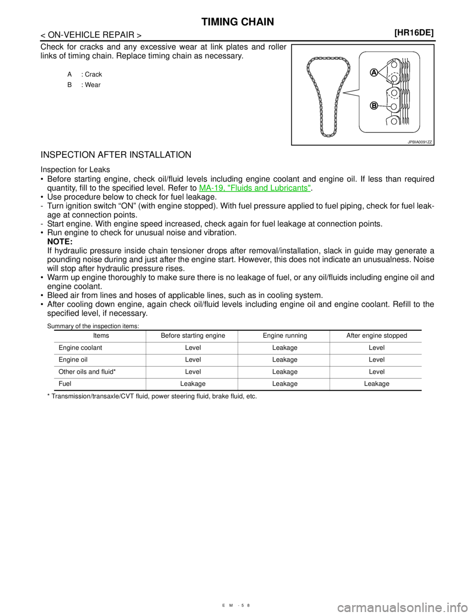
Check for cracks and any excessive wear at link plates and roller
links of timing chain. Replace timing chain as necessary.
INSPECTION AFTER INSTALLATION
Inspection for Leaks
Before starting engine, check oil/fluid levels including engine coolant and engine oil. If less than required
quantity, fill to the specified level. Refer to MA-19, "
Fluids and Lubricants".
Use procedure below to check for fuel leakage.
- Turn ignition switch “ON” (with engine stopped). With fuel pressure applied to fuel piping, check for fuel leak-
age at connection points.
- Start engine. With engine speed increased, check again for fuel leakage at connection points.
Run engine to check for unusual noise and vibration.
NOTE:
If hydraulic pressure inside chain tensioner drops after removal/installation, slack in guide may generate a
pounding noise during and just after the engine start. However, this does not indicate an unusualness. Noise
will stop after hydraulic pressure rises.
Warm up engine thoroughly to make sure there is no leakage of fuel, or any oil/fluids including engine oil and
engine coolant.
Bleed air from lines and hoses of applicable lines, such as in cooling system.
After cooling down engine, again check oil/fluid levels including engine oil and engine coolant. Refill to the
specified level, if necessary.
Summary of the inspection items:
* Transmission/transaxle/CVT fluid, power steering fluid, brake fluid, etc.A: Crack
B: Wear
JPBIA0091ZZ
Items Before starting engine Engine running After engine stopped
Engine coolant Level Leakage Level
Engine oil Level Leakage Level
Other oils and fluid* Level Leakage Level
Fuel Leakage Leakage Leakage
Page 2722 of 5883
CAMSHAFT
EM-75
< ON-VEHICLE REPAIR >[HR16DE]
C
D
E
F
G
H
I
J
K
L
MA
EM
N
P O Inspection for Leaks
The following are procedures for checking fluids leak, lubricates leak.
Before starting engine, check oil/fluid levels including engine coolant and engine oil. If less than required
quantity, fill to the specified level. Refer to MA-19, "
Fluids and Lubricants".
Use procedure below to check for fuel leakage.
- Turn ignition switch “ON” (with engine stopped). With fuel pressure applied to fuel piping, check for fuel leak-
age at connection points.
- Start engine. With engine speed increased, check again for fuel leakage at connection points.
Run engine to check for unusual noise and vibration.
NOTE:
If hydraulic pressure inside timing chain tensioner drops after removal/installation, slack in the guide may
generate a pounding noise during and just after engine start. However, this is normal. Noise will stop after
hydraulic pressure rises.
Warm up engine thoroughly to make sure there is no leakage of fuel, or any oil/fluids including engine oil and
engine coolant.
Bleed air from lines and hoses of applicable lines, such as in cooling system.
After cooling down engine, again check oil/fluid levels including engine oil and engine coolant. Refill to the
specified level, if necessary.
Summary of the inspection items:
*: Transmission/transaxle/CVT fluid, power steering fluid, brake fluid, etc.
Inspection of Camshaft Sprocket (INT) Oil Groove
CAUTION:
Perform this inspection only when DTC P0011 is detected in self-diagnostic results of CONSULT-III
and it is directed according to inspection procedure of EC section. Refer to EC-131, "
Diagnosis Pro-
cedure" (EURO-OBD), EC-484, "Diagnosis Procedure" (WITHOUT EURO-OBD).
Check when engine is cold so as to prevent burns from the splashing engine oil.
1. Check engine oil level. Refer to LU-6, "
Inspection".
2. Perform the following procedure so as to prevent the engine from being unintentionally started while
checking.
a. Release the fuel pressure. Refer to EC-377, "
Inspection" (EURO-OBD), EC-681, "Inspection" (WITHOUT
EURO-OBD).
b. Remove intake manifold. Refer to EM-29, "
Exploded View".
c. Disconnect ignition coil and injector harness connectors. Refer to EM-47, "
Exploded View".
3. Remove intake valve timing control solenoid valve. Refer to EM-50, "
Exploded View".
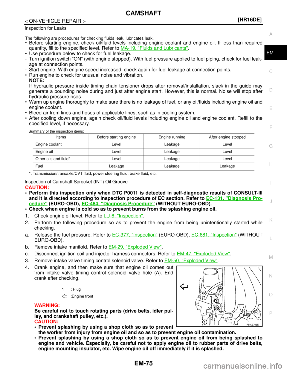
4. Crank engine, and then make sure that engine oil comes out
from intake valve timing control solenoid valve hole (A). End
crank after checking.
WARNING:
Be careful not to touch rotating parts (drive belts, idler pul-
ley, and crankshaft pulley, etc.).
CAUTION:
Prevent splashing by using a shop cloth so as to prevent
the worker from injury from engine oil and so as to prevent engine oil contamination.
Prevent splashing by using a shop cloth so as to prevent engine oil from being splashed to
engine and vehicle. Especially, be careful not to apply engine oil to rubber parts of drive belts,
engine mounting insulator, etc. Wipe engine oil off immediately if it is splashed.
Items Before starting engine Engine running After engine stopped
Engine coolant Level Leakage Level
Engine oil Level Leakage Level
Other oils and fluid* Level Leakage Level
Fuel Leakage Leakage Leakage
1: Plug
:Engine front
PBIC3706E