2007 NISSAN TIIDA air suspension
[x] Cancel search: air suspensionPage 4583 of 5883
REAR SUSPENSION BEAM
RSU-11
< ON-VEHICLE REPAIR >
C
D
F
G
H
I
J
K
L
MA
B
RSU
N
O
P
REAR SUSPENSION BEAM
Removal and InstallationINFOID:0000000001724580
REMOVAL
1. Remove rear tires from vehicle using power tool.
2. Separate parking brake rear cable from rear drum brake and rear suspension beam. Refer to PB-4, "
On-
Vehicle Service" .
3. Remove wheel sensor and wheel sensor harness from wheel hub and bearing assembly and rear suspen-
sion beam. Refer to BRC-83, "
Removal and Installation" .
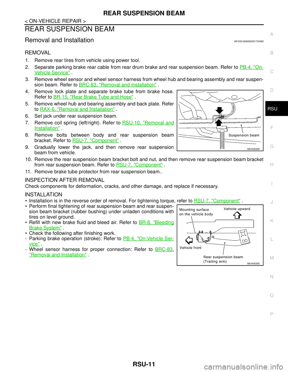
4. Remove lock plate and separate brake tube from brake hose.
Refer to BR-15, "
Rear Brake Tube and Hose" .
5. Remove wheel hub and bearing assembly and back plate. Refer
to RAX-6, "
Removal and Installation" .
6. Set jack under rear suspension beam.
7. Remove coil spring (left/right). Refer to RSU-10, "
Removal and
Installation" .
8. Remove bolts between body and rear suspension beam
bracket. Refer to RSU-7, "
Component" .
9. Gradually lower the jack, and then remove rear suspension
beam from vehicle.
10. Remove the rear suspension beam bracket bolt and nut, and then remove rear suspension beam bracket
from rear suspension beam. Refer to RSU-7, "
Component" .
11. Remove brake tube protector from rear suspension beam..
INSPECTION AFTER REMOVAL
Check components for deformation, cracks, and other damage, and replace if necessary.
INSTALLATION
Installation is in the reverse order of removal. For tightening torque, refer to RSU-7, "Component" .
Perform final tightening of rear suspension beam and rear suspen-
sion beam bracket (rubber bushing) under unladen conditions with
tires on level ground.
Refill with new brake fluid and bleed air. Refer to BR-8, "
Bleeding
Brake System" .
Check the following after finishing work.
- Parking brake operation (stroke): Refer to PB-4, "
On-Vehicle Ser-
vice" .
- Wheel sensor harness for proper connection: Refer to BRC-83,
"Removal and Installation" .
MEIA0029E
MEIA0030E
Page 4860 of 5883
NOISE, VIBRATION AND HARSHNESS (NVH) TROUBLESHOOTING
ST-5
< SYMPTOM DIAGNOSIS >
C
D
E
F
H
I
J
K
L
MA
B
ST
N
O
P
SYMPTOM DIAGNOSIS
NOISE, VIBRATION AND HARSHNESS (NVH) TROUBLESHOOTING
NVH Troubleshooting ChartINFOID:0000000001282490
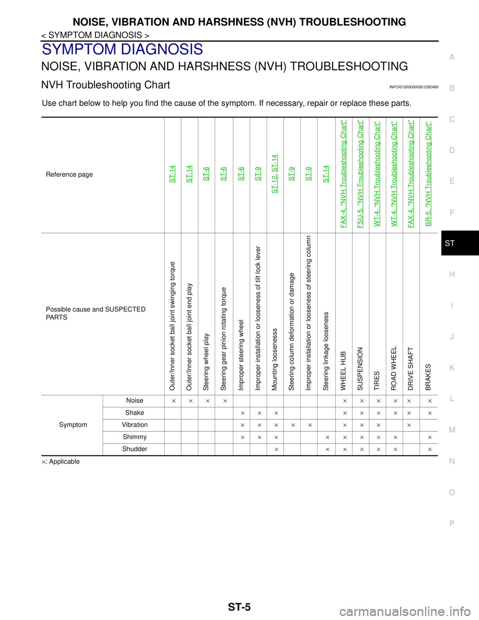
Use chart below to help you find the cause of the symptom. If necessary, repair or replace these parts.
×: ApplicableReference page
ST-14ST-14ST-6ST-6ST-6ST-9
ST-12
, ST-14ST-9ST-9ST-14
FAX-4, "
NVH Troubleshooting Chart
"
FSU-5, "
NVH Troubleshooting Chart
"
WT-4, "
NVH Troubleshooting Chart
"
WT-4, "
NVH Troubleshooting Chart
"
FAX-4, "
NVH Troubleshooting Chart
"
BR-5, "
NVH Troubleshooting Chart
"
Possible cause and SUSPECTED
PA R T S
Outer/Inner socket ball joint swinging torque
Outer/Inner socket ball joint end play
Steering wheel play
Steering gear pinion rotating torque
Improper steering wheel
Improper installation or looseness of tilt lock lever
Mounting loosenesss
Steering column deformation or damage
Improper installation or looseness of steering column
Steering linkage looseness
WHEEL HUB
SUSPENSION
TIRES
ROAD WHEEL
DRIVE SHAFT
BRAKES
SymptomNoise××× × ××××× ×
Shake××× ××××× ×
Vibration××××× ××× ×
Shimmy××× × ×××× ×
Shudder× × ×××× ×
Page 4861 of 5883
ST-6
< ON-VEHICLE MAINTENANCE >
STEERING WHEEL
ON-VEHICLE MAINTENANCE
STEERING WHEEL
On-Vehicle Inspection and ServiceINFOID:0000000001282496
CHECKING CONDITION OF INSTALLATION
Check installation conditions of steering gear assembly, front suspension assembly, axle and steering col-
umn assembly.
Check if movement exists when steering wheel is moved up and down, to the left and right and to the axial
direction.
Check steering gear assembly mounting bolts and nuts for looseness. Refer to ST-12, "
Removal and Instal-
lation" .
CHECKING STEERING WHEEL PLAY
Turn steering wheel so that front wheels come to the straight-ahead position. Start engine and lightly turn
steering wheel to the left and right until front wheels start to move. Measure steering wheel movement on the
outer circumference.
When the measurement value is outside the standard value, check backlash for each joint of steering col-
umn assembly and installation condition of steering gear assembly.
CHECKING NEUTRAL POSITION STEERING WHEEL
Make sure that steering gear assembly, steering column assembly and steering wheel are installed in the
correct position.
Perform neutral position inspection after wheel alignment. Refer to SR-2, "
Precaution for Supplemental
Restraint System (SRS) "AIR BAG" and "SEAT BELT PRE-TENSIONER"" .
Set vehicle to the straight-ahead position and confirm steering wheel is in the neutral position.
Loosen outer socket lock nut and turn inner socket to left and right equally to make fine adjustments if steer-
ing wheel is not in the neutral position.
CHECKING STEERING WHEEL TURNING FORCE
1. Park vehicle on a level and dry surface, set parking brake.
2. Start engine.
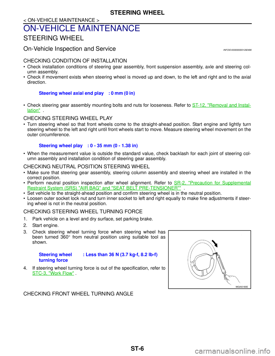
3. Check steering wheel turning force when steering wheel has
been turned 360° from neutral position using suitable tool as
shown.
4. If steering wheel turning force is out of the specification, refer to
STC-3, "
Work Flow" .
CHECKING FRONT WHEEL TURNING ANGLE
Steering wheel axial end play : 0 mm (0 in)
Steering wheel play : 0 - 35 mm (0 - 1.38 in)
Steering wheel
turning force: Less than 36 N (3.7 kg-f, 8.2 lb-f)
WGIA0180E
Page 4867 of 5883
ST-12
< ON-VEHICLE REPAIR >
STEERING GEAR
STEERING GEAR
Removal and InstallationINFOID:0000000001282501
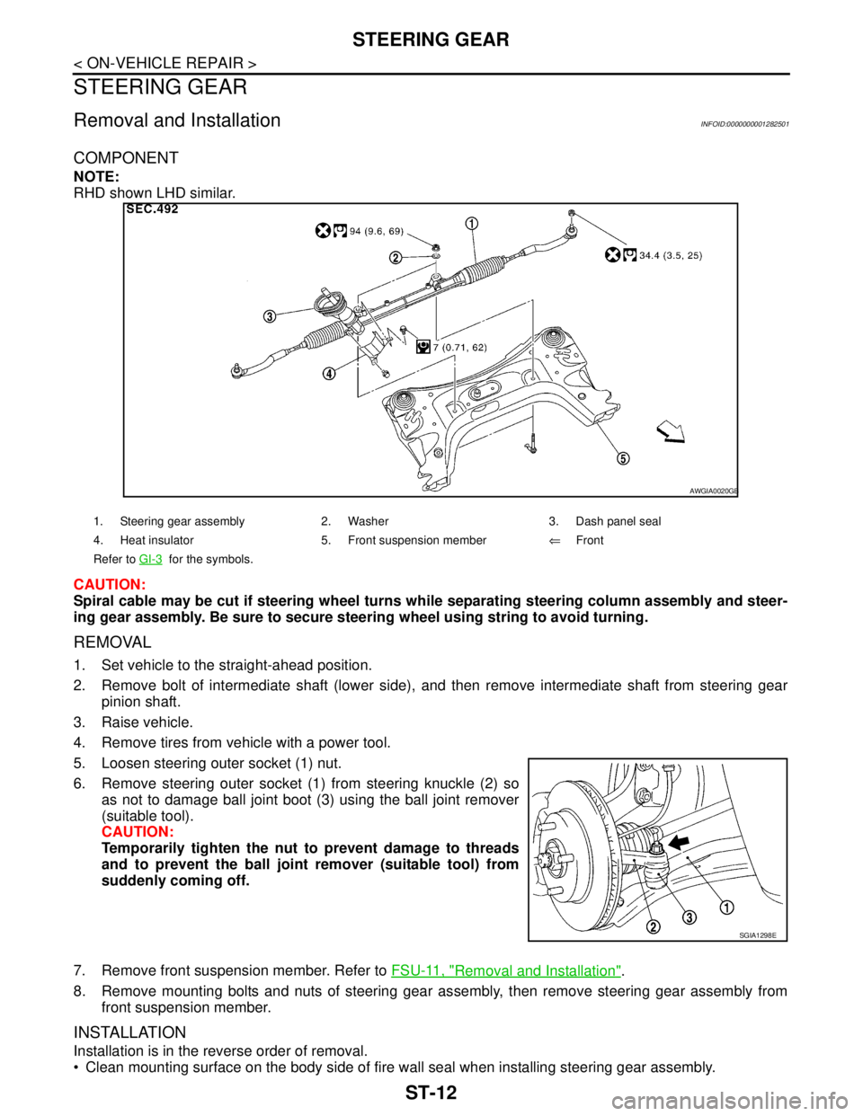
COMPONENT
NOTE:
RHD shown LHD similar.
CAUTION:
Spiral cable may be cut if steering wheel turns while separating steering column assembly and steer-
ing gear assembly. Be sure to secure steering wheel using string to avoid turning.
REMOVAL
1. Set vehicle to the straight-ahead position.
2. Remove bolt of intermediate shaft (lower side), and then remove intermediate shaft from steering gear
pinion shaft.
3. Raise vehicle.
4. Remove tires from vehicle with a power tool.
5. Loosen steering outer socket (1) nut.
6. Remove steering outer socket (1) from steering knuckle (2) so
as not to damage ball joint boot (3) using the ball joint remover
(suitable tool).
CAUTION:
Temporarily tighten the nut to prevent damage to threads
and to prevent the ball joint remover (suitable tool) from
suddenly coming off.
7. Remove front suspension member. Refer to FSU-11, "
Removal and Installation".
8. Remove mounting bolts and nuts of steering gear assembly, then remove steering gear assembly from
front suspension member.
INSTALLATION
Installation is in the reverse order of removal.
Clean mounting surface on the body side of fire wall seal when installing steering gear assembly.
1. Steering gear assembly 2. Washer 3. Dash panel seal
4. Heat insulator 5. Front suspension member⇐Front
Refer to GI-3
for the symbols.
AWGIA0020GB
SGIA1298E
Page 5796 of 5883

WT-1
SUSPENSION
C
D
F
G
H
I
J
K
L
M
SECTION WT
A
B
WT
N
O
PCONTENTS
ROAD WHEELS & TIRES
PRECAUTION ...............................................2
PRECAUTIONS ...................................................2
Precaution for Supplemental Restraint System
(SRS) "AIR BAG" and "SEAT BELT PRE-TEN-
SIONER" ...................................................................
2
PREPARATION ............................................3
PREPARATION ...................................................3
Special Service Tool .................................................3
Commercial Service Tool ..........................................3
SYMPTOM DIAGNOSIS ...............................4
NOISE, VIBRATION AND HARSHNESS
(NVH) TROUBLESHOOTING .............................
4
NVH Troubleshooting Chart ......................................4
ON-VEHICLE MAINTENANCE .....................5
ROAD WHEEL ...................................................5
Inspection .................................................................5
ON-VEHICLE REPAIR ..................................6
ROAD WHEEL TIRE ASSEMBLY .....................6
Balancing Wheels .....................................................6
Rotation ....................................................................6
SERVICE DATA AND SPECIFICATIONS
(SDS) .............................................................
7
SERVICE DATA AND SPECIFICATIONS
(SDS) ..................................................................
7
Road Wheel ..............................................................7
Tire ...........................................................................7
Page 5799 of 5883
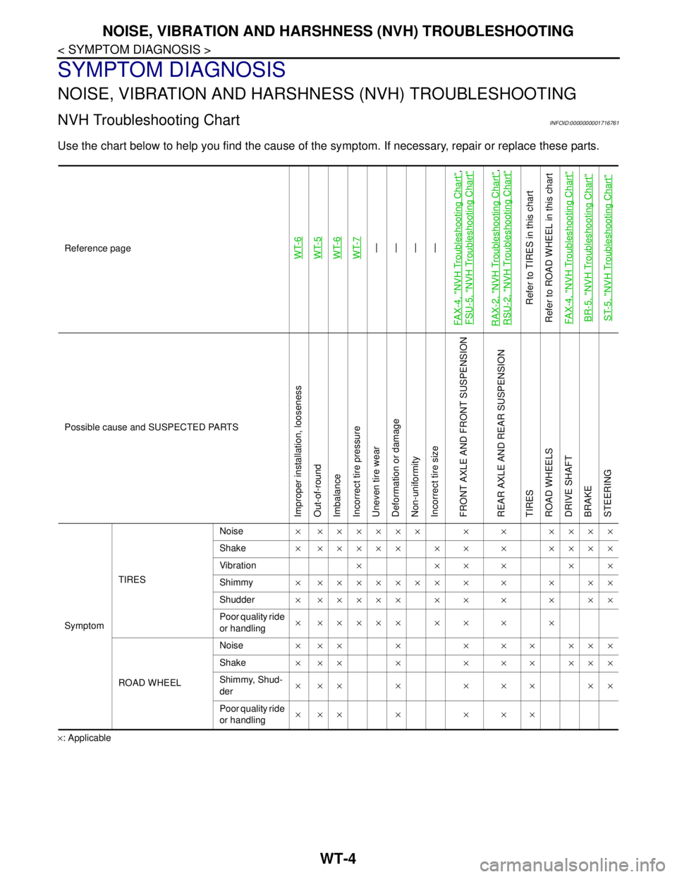
WT-4
< SYMPTOM DIAGNOSIS >
NOISE, VIBRATION AND HARSHNESS (NVH) TROUBLESHOOTING
SYMPTOM DIAGNOSIS
NOISE, VIBRATION AND HARSHNESS (NVH) TROUBLESHOOTING
NVH Troubleshooting ChartINFOID:0000000001716761
Use the chart below to help you find the cause of the symptom. If necessary, repair or replace these parts.
×: ApplicableReference page
WT-6WT-5
WT-6
WT-7—
—
—
—
FA X - 4 , "
NVH Troubleshooting Chart
",
FSU-5, "
NVH Troubleshooting Chart
"
RAX-2, "
NVH Troubleshooting Chart
",
RSU-2, "
NVH Troubleshooting Chart
"
Refer to TIRES in this chart
Refer to ROAD WHEEL in this chart
FAX-4, "
NVH Troubleshooting Chart
"
BR-5, "
NVH Troubleshooting Chart
"
ST-5, "
NVH Troubleshooting Chart
"
Possible cause and SUSPECTED PARTS
Improper installation, looseness
Out-of-round
Imbalance
Incorrect tire pressure
Uneven tire wear
Deformation or damage
Non-uniformity
Incorrect tire size
FRONT AXLE AND FRONT SUSPENSION
REAR AXLE AND REAR SUSPENSION
TIRES
ROAD WHEELS
DRIVE SHAFT
BRAKE
STEERING
SymptomTIRESNoise× ×××××× × × ××××
Shake× ××××× × × × ××××
Vibration××××××
Shimmy× ××××××× × × × ××
Shudder× ××××× × × × × ××
Poor quality ride
or handling× ××××× × × × ×
ROAD WHEELNoise× ×× × × × × ×××
Shake× ×× × × × × ×××
Shimmy, Shud-
der×××× ×××××
Poor quality ride
or handling××× × × × ×