2007 NISSAN TIIDA engine coolant
[x] Cancel search: engine coolantPage 4287 of 5883

ENGINE MAINTENANCE (K9K)
MA-47
< ON-VEHICLE MAINTENANCE >
C
D
E
F
G
H
I
J
K
L
MB
MAN
OA
ENGINE OIL : InspectionINFOID:0000000001730878
OIL LEVEL AND MUDDINESS
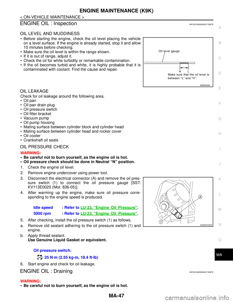
Before starting the engine, check the oil level placing the vehicle
on a level surface. If the engine is already started, stop it and allow
10 minutes before checking.
Make sure the oil level is within the range shown.
If it is out of range, adjust it.
Check the oil for white turbidity or remarkable contamination.
If the oil becomes turbid and white, it is highly probable that it is
contaminated with coolant. Find the cause and repair.
OIL LEAKAGE
Check for oil leakage around the following area.
Oil pan
Oil pan drain plug
Oil pressure switch
Oil filter bracket
Vacuum pump
Oil pump housing
Mating surface between cylinder block and cylinder head
Mating surface between cylinder head and rocker cover
Oil cooler
Crankshaft oil seals
OIL PRESSURE CHECK
WARNING:
Be careful not to burn yourself, as the engine oil is hot.
Oil pressure check should be done in Neutral “N” position.
1. Check the engine oil level.
2. Remove engine undercover using power tool.
3. Disconnect the electrical connector (A) and remove the oil pres-
sure switch (1) to connect the oil pressure gauge [SST:
KV113E0020 (Mot. 836-05)].
4. After warming up the engine, make sure oil pressure corre-
sponding to the engine speed is produced.
5. After checking, install the oil pressure switch (1) as follows.
a. Remove old sealant adhering to the oil pressure switch (1) and
engine.
b. Apply thread sealant.
Use Genuine Liquid Gasket or equivalent.
6. Start engine and check for oil leakage.
ENGINE OIL : DrainingINFOID:0000000001730876
WARNING:
Be careful not to burn yourself, as the engine oil is hot.
MBIB0548E
Idle speed : Refer to LU-33, "EngineOilPressure".
3000 rpm : Refer to LU-33, "
EngineOilPressure".
Oil pressure switch:
: 25 N·m (2.55 kg-m, 18.4 ft-lb)
ALBIA0418ZZ
Page 4314 of 5883

MWI
METER SYSTEM
MWI-7
< FUNCTION DIAGNOSIS >
C
D
E
F
G
H
I
J
K
L
MB A
O
P
METER SYSTEM : Component DescriptionINFOID:0000000001537306
SPEEDOMETER
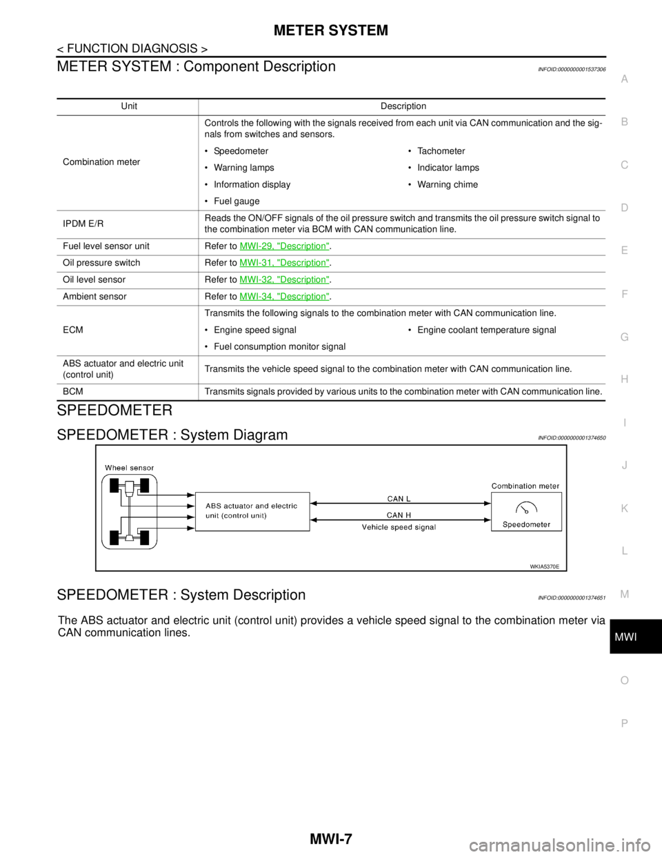
SPEEDOMETER : System DiagramINFOID:0000000001374650
SPEEDOMETER : System DescriptionINFOID:0000000001374651
The ABS actuator and electric unit (control unit) provides a vehicle speed signal to the combination meter via
CAN communication lines.
Unit Description
Combination meterControls the following with the signals received from each unit via CAN communication and the sig-
nals from switches and sensors.
Speedometer Tachometer
Warning lamps Indicator lamps
Information display Warning chime
Fuel gauge
IPDM E/RReads the ON/OFF signals of the oil pressure switch and transmits the oil pressure switch signal to
the combination meter via BCM with CAN communication line.
Fuel level sensor unit Refer to MWI-29, "
Description".
Oil pressure switch Refer to MWI-31, "
Description".
Oil level sensor Refer to MWI-32, "
Description".
Ambient sensor Refer to MWI-34, "
Description".
ECMTransmits the following signals to the combination meter with CAN communication line.
Engine speed signal Engine coolant temperature signal
Fuel consumption monitor signal
ABS actuator and electric unit
(control unit)Transmits the vehicle speed signal to the combination meter with CAN communication line.
BCM Transmits signals provided by various units to the combination meter with CAN communication line.
WKIA5370E
Page 4329 of 5883

MWI-22
< FUNCTION DIAGNOSIS >
DIAGNOSIS SYSTEM (METER)
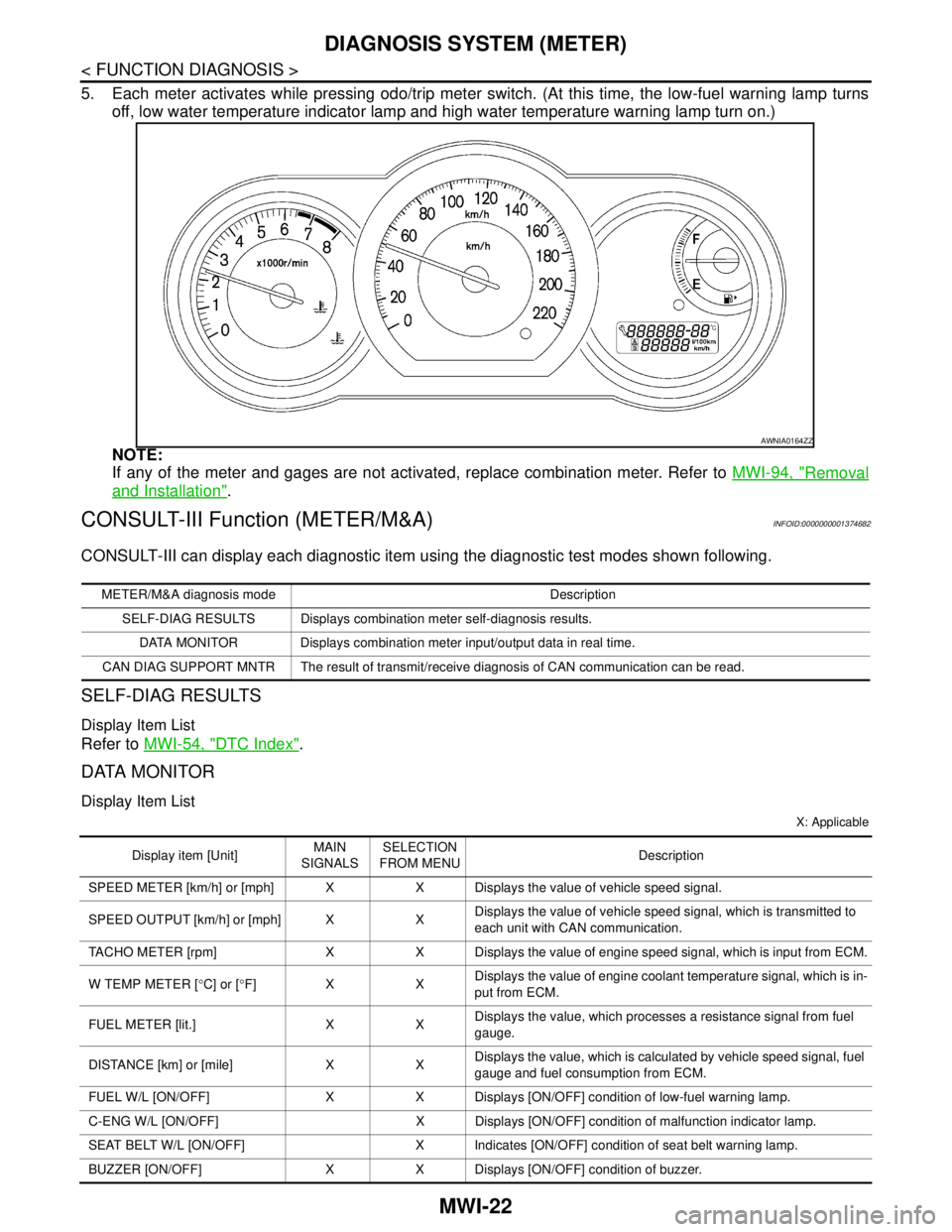
5. Each meter activates while pressing odo/trip meter switch. (At this time, the low-fuel warning lamp turns
off, low water temperature indicator lamp and high water temperature warning lamp turn on.)
NOTE:
If any of the meter and gages are not activated, replace combination meter. Refer to MWI-94, "
Removal
and Installation".
CONSULT-III Function (METER/M&A)INFOID:0000000001374682
CONSULT-III can display each diagnostic item using the diagnostic test modes shown following.
SELF-DIAG RESULTS
Display Item List
Refer to MWI-54, "DTC Index".
DATA MONITOR
Display Item List
X: Applicable
AWNIA0164ZZ
METER/M&A diagnosis mode Description
SELF-DIAG RESULTS Displays combination meter self-diagnosis results.
DATA MONITOR Displays combination meter input/output data in real time.
CAN DIAG SUPPORT MNTR The result of transmit/receive diagnosis of CAN communication can be read.
Display item [Unit]MAIN
SIGNALSSELECTION
FROM MENUDescription
SPEED METER [km/h] or [mph] X X Displays the value of vehicle speed signal.
SPEED OUTPUT [km/h] or [mph] X XDisplays the value of vehicle speed signal, which is transmitted to
each unit with CAN communication.
TACHO METER [rpm] X X Displays the value of engine speed signal, which is input from ECM.
W TEMP METER [°C] or [°F] X XDisplays the value of engine coolant temperature signal, which is in-
put from ECM.
FUEL METER [lit.] X XDisplays the value, which processes a resistance signal from fuel
gauge.
DISTANCE [km] or [mile] X XDisplays the value, which is calculated by vehicle speed signal, fuel
gauge and fuel consumption from ECM.
FUEL W/L [ON/OFF] X X Displays [ON/OFF] condition of low-fuel warning lamp.
C-ENG W/L [ON/OFF] X Displays [ON/OFF] condition of malfunction indicator lamp.
SEAT BELT W/L [ON/OFF] X Indicates [ON/OFF] condition of seat belt warning lamp.
BUZZER [ON/OFF] X X Displays [ON/OFF] condition of buzzer.
Page 4344 of 5883

MWI
COMBINATION METER
MWI-37
< ECU DIAGNOSIS >
C
D
E
F
G
H
I
J
K
L
MB A
O
P
11 LG Brake fluid level switch ONBrake fluid level low 0
Brake fluid level normal Battery voltage
16 VSteering switch (trip comput-
er) signalONPress the steering switch (trip
computer)0
Other than the above 5
19 V Ambient sensor signal ON —
20 BR Ambient sensor ground ON — 0
21
BGround — — 0 22
23
24 V Fuel level sensor ground (-) ON — 0
25 RAuto A/C sense signal (with
auto A/C)ON — 5V
27 G Battery power supply OFF — Battery voltage
28 SB Ignition switch ON or START ON — Battery voltage
30 G Stop lamp switch ONBrake pedal depressed Battery voltage
Brake pedal released 0
31 V A/T N-range input (with A/T) ONTransmission gear selector lever
in N positionBattery voltage
Transmission gear selector lever
other than N position0
32 W A/T P-range input (with A/T) ONTransmission gear selector lever
in P positionBattery voltage
Transmission gear selector lever
other than P position0
33 Y A/T PN output (with A/T) ONTransmission gear selector lever
in P or N position0
Transmission gear selector lever
other than P or N positionBattery voltage
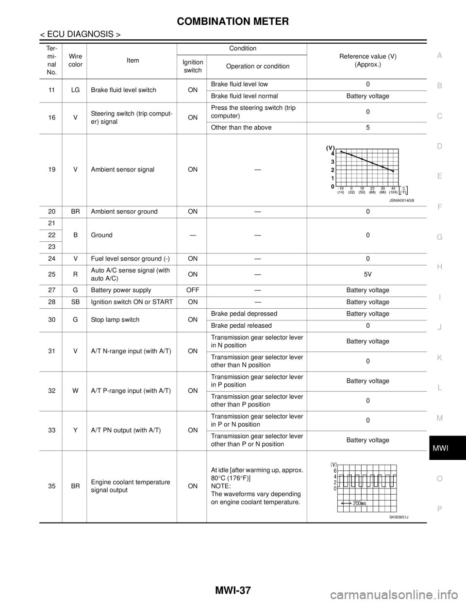
35 BREngine coolant temperature
signal outputONAt idle [after warming up, approx.
80°C (176°F)]
NOTE:
The waveforms vary depending
on engine coolant temperature. Te r -
mi-
nal
No.Wire
colorItemCondition
Reference value (V)
(Approx.) Ignition
switchOperation or condition
JSNIA0014GB
SKIB3651J
Page 4362 of 5883

MWI
BCM (BODY CONTROL MODULE)
MWI-55
< ECU DIAGNOSIS >
C
D
E
F
G
H
I
J
K
L
MB A
O
P
BCM (BODY CONTROL MODULE)
Reference ValueINFOID:0000000001713119
VALUES ON THE DIAGNOSIS TOOL
Monitor Item Condition Value/Status
AIR COND SWA/C switch OFF OFF
A/C switch ON ON
AUT LIGHT SYSOutside of the room is dark OFF
Outside of the room is bright ON
AUTO LIGHT SWLighting switch OFF OFF
Lighting switch AUTO ON
BACK DOOR SWBack door closed OFF
Back door opened ON
BATTERY VOLT
NOTE:
Diesel engine models
onlyIgnition switch ONApproximately the same as power
supply voltage
CDL LOCK SWDoor lock/unlock switch does not operate OFF
Press door lock/unlock switch to the LOCK side ON
CDL UNLOCK SWDoor lock/unlock switch does not operate OFF
Press door lock/unlock switch to the UNLOCK side ON
DOOR SW-ASPassenger door closed OFF
Passenger door opened ON
DOOR SW-DRDriver door closed OFF
Driver door opened ON
DOOR SW-RLRear LH door closed OFF
Rear LH door opened ON
DOOR SW-RRRear RH door closed OFF
Rear RH door opened ON
ELEC PWR CUT
NOTE:
Diesel engine models
onlyEngine runningFan switch ON (when engine coolant is
cool)
NOTE:
Depending on the ambient tempera-
ture, battery voltage, etc.OFF
The current status maintained with the
signal from ECM received.FREEZ
Fan switch OFF
Fan switch ON after engine warming
UP
NOTE:
Depending on the engine coolant
temperature, ambient temperature,
battery voltage, etc.INHBT
ENG COOLNT T
NOTE:
Diesel engine models
onlyEngine runningApproximately the same as engine
water temperature
ENGINE RPM
NOTE:
Diesel engine models
onlyEngine runningApproximately the same as tachom-
eter reading
Page 4382 of 5883

MWI
IPDM E/R (INTELLIGENT POWER DISTRIBUTION MODULE ENGINE ROOM)
MWI-75
< ECU DIAGNOSIS >
C
D
E
F
G
H
I
J
K
L
MB A
O
P
IPDM E/R (INTELLIGENT POWER DISTRIBUTION MODULE ENGINE
ROOM)
Reference ValueINFOID:0000000001713125
VALUES ON THE DIAGNOSIS TOOL
Monitor Item Condition Value/Status
MOTOR FAN REQ Engine idle speedChanges depending on engine
coolant temperature, air conditioner
operation status, vehicle speed,
etc.0 - 100 %
A/C COMP REQA/C switch OFF OFF
A/C switch ON ON
TA I L & C L R R E QLighting switch OFF OFF
Lighting switch 1ST, 2ND, HI or AUTO (Light is illuminated) ON
HL LO REQLighting switch OFF OFF
Lighting switch 2ND HI or AUTO (Light is illuminated) ON
HL HI REQLighting switch OFF OFF
Lighting switch HI ON
FR FOG REQLighting switch 2ND or AUTO (Light
is illuminated)Front fog lamp switch OFF OFF
Front fog lamp switch ON
Daytime light activated ON
HL WASHER REQNOTE:
This item is displayed, but cannot be monitored.OFF
FR WIP REQ Ignition switch ONFront wiper switch OFF STOP
Front wiper switch INT 1LOW
Front wiper switch LO LOW
Front wiper switch HI HI
WIP AUTO STOP Ignition switch ONFront wiper stop position STOP P
Any position other than front wiper
stop positionACT P
WIP PROT Ignition switch ONFront wiper operates normally OFF
Front wiper stops at fail-safe opera-
tionBLOCK
ST RLY REQIgnition switch OFF or ACC OFF
Ignition switch START ON
IGN RLYIgnition switch OFF or ACC OFF
Ignition switch ON ON
RR DEF REQRear defogger switch OFF OFF
Rear defogger switch ON ON
OIL P SWIgnition switch OFF, ACC or engine running OPEN
Ignition switch ON CLOSE
DTRL REQNOTE:
This item is displayed, but cannot be monitored.OFF
HOOD SWNOTE:
This item is displayed, but cannot be monitored.OFF
Page 4424 of 5883
![NISSAN TIIDA 2007 Service Repair Manual PCS-10
< FUNCTION DIAGNOSIS >[IPDM E/R]
DIAGNOSIS SYSTEM (IPDM E/R)
DIAGNOSIS SYSTEM (IPDM E/R)
Diagnosis DescriptionINFOID:0000000001697589
AUTO ACTIVE TEST
Description
In auto active test mode, the NISSAN TIIDA 2007 Service Repair Manual PCS-10
< FUNCTION DIAGNOSIS >[IPDM E/R]
DIAGNOSIS SYSTEM (IPDM E/R)
DIAGNOSIS SYSTEM (IPDM E/R)
Diagnosis DescriptionINFOID:0000000001697589
AUTO ACTIVE TEST
Description
In auto active test mode, the](/manual-img/5/57395/w960_57395-4423.png)
PCS-10
< FUNCTION DIAGNOSIS >[IPDM E/R]
DIAGNOSIS SYSTEM (IPDM E/R)
DIAGNOSIS SYSTEM (IPDM E/R)
Diagnosis DescriptionINFOID:0000000001697589
AUTO ACTIVE TEST
Description
In auto active test mode, the IPDM E/R sends a drive signal to the following systems to check their operation.
Oil pressure low/coolant pressure high warning indicator
Oil pressure gauge
Rear window defogger
Front wipers
Tail, license and parking lamps
Front fog lamps
Headlamps (Hi, Lo)
A/C compressor (magnetic clutch)
Cooling fan
Operation Procedure
1. Close the hood and front door RH, and lift the wiper arms from the windshield (to prevent windshield dam-
age due to wiper operation).
NOTE:
When auto active test is performed with hood opened, sprinkle water on windshield before hand.
2. Turn ignition switch OFF.
3. Turn the ignition switch ON and, within 20 seconds, press the front door switch LH 10 times. Then turn the
ignition switch OFF.
4. Turn the ignition switch ON within 10 seconds. After that the horn sounds once and the auto active test
starts.
5. After a series of the following operations is repeated 3 times, auto active test is completed.
NOTE:
When auto active test mode has to be cancelled halfway through test, turn ignition switch OFF.
CAUTION:
• If auto active test mode cannot be actuated, check door switch system. Refer to DLK-65, "
DRIVER
SIDE : Description" (with Intelligent Key system), DLK-499, "DRIVER SIDE : Description" (without
Intelligent Key system).
Do not start the engine.
Inspection in Auto Active Test Mode
Page 4431 of 5883
![NISSAN TIIDA 2007 Service Repair Manual PCS
IPDM E/R (INTELLIGENT POWER DISTRIBUTION MODULE ENGINE ROOM)
PCS-17
< ECU DIAGNOSIS >[IPDM E/R]
C
D
E
F
G
H
I
J
K
L B A
O
P N
ECU DIAGNOSIS
IPDM E/R (INTELLIGENT POWER DISTRIBUTION MODULE ENGINE
R NISSAN TIIDA 2007 Service Repair Manual PCS
IPDM E/R (INTELLIGENT POWER DISTRIBUTION MODULE ENGINE ROOM)
PCS-17
< ECU DIAGNOSIS >[IPDM E/R]
C
D
E
F
G
H
I
J
K
L B A
O
P N
ECU DIAGNOSIS
IPDM E/R (INTELLIGENT POWER DISTRIBUTION MODULE ENGINE
R](/manual-img/5/57395/w960_57395-4430.png)
PCS
IPDM E/R (INTELLIGENT POWER DISTRIBUTION MODULE ENGINE ROOM)
PCS-17
< ECU DIAGNOSIS >[IPDM E/R]
C
D
E
F
G
H
I
J
K
L B A
O
P N
ECU DIAGNOSIS
IPDM E/R (INTELLIGENT POWER DISTRIBUTION MODULE ENGINE
ROOM)
Reference ValueINFOID:0000000001697595
VALUES ON THE DIAGNOSIS TOOL
Monitor Item Condition Value/Status
MOTOR FAN REQ Engine idle speedChanges depending on engine
coolant temperature, air conditioner
operation status, vehicle speed,
etc.0 - 100 %
A/C COMP REQA/C switch OFF OFF
A/C switch ON ON
TA I L & C L R R E QLighting switch OFF OFF
Lighting switch 1ST, 2ND, HI or AUTO (Light is illuminated) ON
HL LO REQLighting switch OFF OFF
Lighting switch 2ND HI or AUTO (Light is illuminated) ON
HL HI REQLighting switch OFF OFF
Lighting switch HI ON
FR FOG REQLighting switch 2ND or AUTO (Light
is illuminated)Front fog lamp switch OFF OFF
Front fog lamp switch ON
Daytime light activated ON
HL WASHER REQNOTE:
This item is displayed, but cannot be monitored.OFF
FR WIP REQ Ignition switch ONFront wiper switch OFF STOP
Front wiper switch INT 1LOW
Front wiper switch LO LOW
Front wiper switch HI HI
WIP AUTO STOP Ignition switch ONFront wiper stop position STOP P
Any position other than front wiper
stop positionACT P
WIP PROT Ignition switch ONFront wiper operates normally OFF
Front wiper stops at fail-safe opera-
tionBLOCK
ST RLY REQIgnition switch OFF or ACC OFF
Ignition switch START ON
IGN RLYIgnition switch OFF or ACC OFF
Ignition switch ON ON
RR DEF REQRear defogger switch OFF OFF
Rear defogger switch ON ON
OIL P SWIgnition switch OFF, ACC or engine running OPEN
Ignition switch ON CLOSE
DTRL REQNOTE:
This item is displayed, but cannot be monitored.OFF
HOOD SWNOTE:
This item is displayed, but cannot be monitored.OFF