2007 NISSAN TIIDA light
[x] Cancel search: lightPage 3583 of 5883
![NISSAN TIIDA 2007 Service Repair Manual HAC-250
< COMPONENT DIAGNOSIS >[AUTO AIR CONDITIONER (W/NAVI)]
SUNLOAD SENSOR
SUNLOAD SENSOR
Component DescriptionINFOID:0000000001547363
COMPONENT DESCRIPTION
Sunload Sensor
The sunload sensor (1) is NISSAN TIIDA 2007 Service Repair Manual HAC-250
< COMPONENT DIAGNOSIS >[AUTO AIR CONDITIONER (W/NAVI)]
SUNLOAD SENSOR
SUNLOAD SENSOR
Component DescriptionINFOID:0000000001547363
COMPONENT DESCRIPTION
Sunload Sensor
The sunload sensor (1) is](/manual-img/5/57395/w960_57395-3582.png)
HAC-250
< COMPONENT DIAGNOSIS >[AUTO AIR CONDITIONER (W/NAVI)]
SUNLOAD SENSOR
SUNLOAD SENSOR
Component DescriptionINFOID:0000000001547363
COMPONENT DESCRIPTION
Sunload Sensor
The sunload sensor (1) is located on the instrument upper mask. It
detects sunload entering through windshield by means of a photo
diode. The sensor converts the sunload into a current value which is
then input into the front air control.
SUNLOAD INPUT PROCESS
The front air control also includes a processing circuit which averages the variations in detected sunload over
a period of time. This prevents drastic swings in the ATC system operation due to small or quick variations in
detected sunload.
For example, consider driving along a road bordered by an occasional group of large trees. The sunload
detected by the sunload sensor will vary whenever the trees obstruct the sunlight. The processing circuit aver-
ages the detected sunload over a period of time, so that the (insignificant) effect of the trees momentarily
obstructing the sunlight does not cause any change in the ATC system operation. On the other hand, shortly
after entering a long tunnel, the system will recognize the change in sunload, and the system will react accord-
ingly.
Sunload Sensor Diagnosis ProcedureINFOID:0000000001547364
DIAGNOSTIC PROCEDURE FOR SUNLOAD SENSOR
SYMPTOM: Sunload sensor circuit is open or shorted.
LEDs of intake switch (FRE, REC) does not illuminate as a result of
performing self-diagnosis STEP-2.
1.CHECK VOLTAGE BETWEEN SUNLOAD SENSOR AND GROUND
1. Turn ignition switch OFF.
2. Disconnect sunload sensor connector.
3. Turn ignition switch ON.
4. Check voltage between sunload sensor harness connector M94
terminal 1 and ground.
Is the inspection result normal
SJIA0819E
AWIIA0347GB
Te r m i n a l s
Voltag e
(Approx.) (+) (−)
Connector Terminal
Ground
Sunload sensor: M94 1 5V
SJIA0821E
Page 3613 of 5883
![NISSAN TIIDA 2007 Service Repair Manual HAC-280
< ECU DIAGNOSIS >[AUTO AIR CONDITIONER (W/NAVI)]
AIR CONDITIONER CONTROL
16 GR Illumination signal ON Light switch: ON Approx. 12
18 O Power supply for IGN 1 ON - Battery voltage
19 LG Power s NISSAN TIIDA 2007 Service Repair Manual HAC-280
< ECU DIAGNOSIS >[AUTO AIR CONDITIONER (W/NAVI)]
AIR CONDITIONER CONTROL
16 GR Illumination signal ON Light switch: ON Approx. 12
18 O Power supply for IGN 1 ON - Battery voltage
19 LG Power s](/manual-img/5/57395/w960_57395-3612.png)
HAC-280
< ECU DIAGNOSIS >[AUTO AIR CONDITIONER (W/NAVI)]
AIR CONDITIONER CONTROL
16 GR Illumination signal ON Light switch: ON Approx. 12
18 O Power supply for IGN 1 ON - Battery voltage
19 LG Power supply for BAT OFF - Battery voltage
20 B Ground ON - Approx. 0
21 GR Blower PWM ON FAN speed: 1st step (manual)
22 P FAN ON signal ON FAN speed: 1st step (manual)
23 O Compressor ON signal ONA/C switch: ON
(Blower motor operates.)
24 WRear window defogger ON
signalONWhen rear window defogger
switch is depressed.Approx. 0
When rear window defogger
switch is released.Approx. 5
25 BR
Air mix door motor drive sig-
nalONImmediately after temperature
adjustment dial operation. 26 G
27 LG
28 R
30 V PTC ON/OFF signal ONBlower fan: ON Approx. 0
Blower fan: OFF Approx. 5
31 G Intake door motor drive signal ONIntake
switchREC→FRE Approx. 0
FRE→REC Approx. 12
32 V Intake door motor drive signal ONIntake
switchREC→FRE Approx. 12
FRE→REC Approx. 0
33 GR
Mode door motor drive signal ONImmediately after mode control
dial operation. 34 W
35 Y
36 V Te r m i n a l
No.Wire
colorItemIgnition
switchConditionVoltag e
(V)
ZJIA0863J
ZJIA0583J
ZJIA0584J
HAK0627D
HAK0627D
Page 3638 of 5883
![NISSAN TIIDA 2007 Service Repair Manual INSUFFICIENT COOLING
HAC-305
< SYMPTOM DIAGNOSIS >[AUTO AIR CONDITIONER (W/NAVI)]
C
D
E
F
G
H
J
K
L
MA
B
HAC
N
O
P Both High- and Low-pressure Sides are Too Low
Low-pressure Side Sometimes Becomes Neg NISSAN TIIDA 2007 Service Repair Manual INSUFFICIENT COOLING
HAC-305
< SYMPTOM DIAGNOSIS >[AUTO AIR CONDITIONER (W/NAVI)]
C
D
E
F
G
H
J
K
L
MA
B
HAC
N
O
P Both High- and Low-pressure Sides are Too Low
Low-pressure Side Sometimes Becomes Neg](/manual-img/5/57395/w960_57395-3637.png)
INSUFFICIENT COOLING
HAC-305
< SYMPTOM DIAGNOSIS >[AUTO AIR CONDITIONER (W/NAVI)]
C
D
E
F
G
H
J
K
L
MA
B
HAC
N
O
P Both High- and Low-pressure Sides are Too Low
Low-pressure Side Sometimes Becomes Negative
Gauge indication Refrigerant cycle Probable cause Corrective action
High-pressure side is too low
and low-pressure side is too
high.High- and low-pressure sides
become equal soon after com-
pressor operation stops.Compressor pressure operation
is improper.
↓
Damaged inside compressor
packings.Replace compressor.
No temperature difference be-
tween high- and low-pressure
sides.Compressor pressure operation
is improper.
↓
Damaged inside compressor
packings.Replace compressor.
AC356A
Gauge indication Refrigerant cycle Probable cause Corrective action
Both high- and low-pressure
sides are too low. There is a big temperature dif-
ference between liquid tank
outlet and inlet. Outlet tem-
perature is extremely low.
Liquid tank inlet and expan-
sion valve are frosted.Liquid tank inside is slightly
clogged. Replace liquid tank.
Check oil for contamination.
Temperature of expansion
valve inlet is extremely low as
compared with areas near liq-
uid tank.
Expansion valve inlet may be
frosted.
Temperature difference oc-
curs somewhere in high-pres-
sure side.High-pressure pipe located be-
tween liquid tank and expansion
valve is clogged. Check and repair malfunc-
tioning parts.
Check oil for contamination.
Expansion valve and liquid tank
are warm or only cool when
touched.Low refrigerant charge.
↓
Leaking fittings or componentsCheck refrigerant for leaks.
Refer to HA-22, "
Checking of
Refrigerant Leaks".
There is a big temperature dif-
ference between expansion
valve inlet and outlet while the
valve itself is frosted.Expansion valve closes a little
compared with the specification.
↓
1. Improper expansion valve
adjustment.
2. Malfunctioning expansion
valve.
3. Outlet and inlet may be
clogged. Remove foreign particles by
using compressed air.
Replace expansion valve.
Check oil for contamination.
An area of the low-pressure pipe
is colder than areas near the
evaporator outlet.Low-pressure pipe is clogged or
crushed. Check and repair malfunc-
tioning parts.
Check oil for contamination.
Air flow volume is not enough or
is too low.Evaporator is frozen. Check intake sensor circuit.
Refer to HAC-229, "
Intake
Door Motor Component
Function Check".
Replace compressor.
Repair evaporator fins.
Replace evaporator.
Refer to HAC-233, "
Front
Blower Motor Component
Function Check".
AC353A
Page 3652 of 5883

INL-1
DRIVER CONTROLS
C
D
E
F
G
H
I
J
K
M
SECTION INL
A
B
INL
N
O
P
CONTENTS
INTERIOR LIGHTING SYSTEM
BASIC INSPECTION ....................................2
DIAGNOSIS AND REPAIR WORKFLOW ..........2
Work Flow .................................................................2
FUNCTION DIAGNOSIS ...............................5
INTERIOR ROOM LAMP CONTROL SYSTEM
.....
5
System Diagram ........................................................5
System Description ...................................................5
Component Parts Location ........................................6
Component Description ............................................6
ILLUMINATION CONTROL SYSTEM .................8
System Diagram ........................................................8
System Description ...................................................8
Component Parts Location ........................................8
Component Description .............................................9
DIAGNOSIS SYSTEM (BCM) ............................10
COMMON ITEM .........................................................10
COMMON ITEM : CONSULT-III Function (BCM -
COMMON ITEM) .....................................................
10
INT LAMP ..................................................................10
INT LAMP : CONSULT-III Function (BCM - INT
LAMP) .....................................................................
10
BATTERY SAVER .....................................................12
BATTERY SAVER : CONSULT-III Function (BCM
- BATTERY SAVER) ...............................................
12
COMPONENT DIAGNOSIS .........................14
POWER SUPPLY AND GROUND CIRCUIT ......14
BCM ...........................................................................14
BCM : Diagnosis Procedure ....................................14
INTERIOR ROOM LAMP POWER SUPPLY
CIRCUIT ............................................................
15
Description ...............................................................15
Component Function Check ....................................15
Diagnosis Procedure ...............................................15
INTERIOR ROOM LAMP CONTROL SYSTEM
...
17
Wiring Diagram - INTERIOR ROOM LAMP - ..........17
ILLUMINATION .................................................20
Wiring Diagram - ILLUMINATION - .........................20
ECU DIAGNOSIS .........................................22
BCM (BODY CONTROL MODULE) .................22
Description ...............................................................22
SYMPTOM DIAGNOSIS ..............................23
INTERIOR LIGHTING SYSTEM SYMPTOMS ...23
Symptom Table .......................................................23
PRECAUTION ..............................................24
PRECAUTIONS .................................................24
Supplemental Restraint System (SRS) "AIR BAG"
and "SEAT BELT PRE-TENSIONER" .....................
24
General precautions for service operations .............24
ON-VEHICLE REPAIR .................................25
INTERIOR ROOM LAMP ..................................25
Removal and Installation .........................................25
SERVICE DATA AND SPECIFICATIONS
(SDS) ............................................................
28
SERVICE DATA AND SPECIFICATIONS
(SDS) .................................................................
28
Bulb Specifications ..................................................28
Page 3659 of 5883

INL-8
< FUNCTION DIAGNOSIS >
ILLUMINATION CONTROL SYSTEM
ILLUMINATION CONTROL SYSTEM
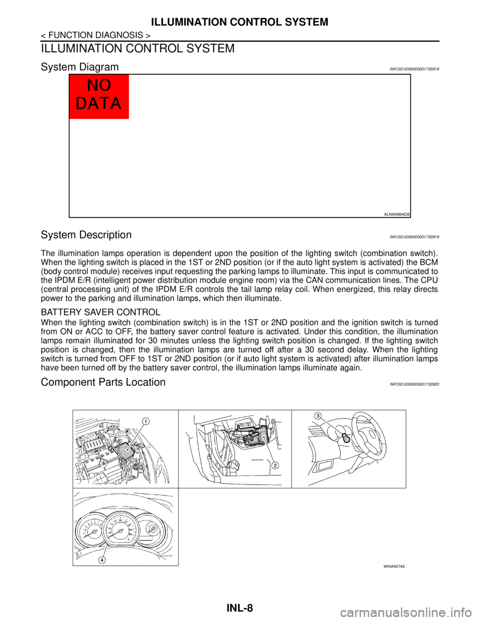
System DiagramINFOID:0000000001730918
System DescriptionINFOID:0000000001730919
The illumination lamps operation is dependent upon the position of the lighting switch (combination switch).
When the lighting switch is placed in the 1ST or 2ND position (or if the auto light system is activated) the BCM
(body control module) receives input requesting the parking lamps to illuminate. This input is communicated to
the IPDM E/R (intelligent power distribution module engine room) via the CAN communication lines. The CPU
(central processing unit) of the IPDM E/R controls the tail lamp relay coil. When energized, this relay directs
power to the parking and illumination lamps, which then illuminate.
BATTERY SAVER CONTROL
When the lighting switch (combination switch) is in the 1ST or 2ND position and the ignition switch is turned
from ON or ACC to OFF, the battery saver control feature is activated. Under this condition, the illumination
lamps remain illuminated for 30 minutes unless the lighting switch position is changed. If the lighting switch
position is changed, then the illumination lamps are turned off after a 30 second delay. When the lighting
switch is turned from OFF to 1ST or 2ND position (or if auto light system is activated) after illumination lamps
have been turned off by the battery saver control, the illumination lamps illuminate again.
Component Parts LocationINFOID:0000000001730920
ALNIA0894GB
WKIA5674E
Page 3660 of 5883

ILLUMINATION CONTROL SYSTEM
INL-9
< FUNCTION DIAGNOSIS >
C
D
E
F
G
H
I
J
K
MA
B
INL
N
O
P
Component DescriptionINFOID:0000000001730921
1. IPDM E/R E46, E47, E48 2. BCM M18, M19, M20 (view with glove
box removed)3. Combination switch M28
4. Combination meter
Part name Description
BCMThe BCM monitors the lighting switch position with the combina-
tion switch reading function. The BCM requests, via CAN com-
munication, that the IPDM E/R activate the tail lamp relay.
IPDM E/RThe IPDM E/R activates the tail lamp relay based on inputs re-
ceived from the BCM via the CAN communication network.
Combination switchThe combination switch provides input to the BCM about the light-
ing switch position.
Page 3674 of 5883

INTERIOR LIGHTING SYSTEM SYMPTOMS
INL-23
< SYMPTOM DIAGNOSIS >
C
D
E
F
G
H
I
J
K
MA
B
INL
N
O
P
SYMPTOM DIAGNOSIS
INTERIOR LIGHTING SYSTEM SYMPTOMS
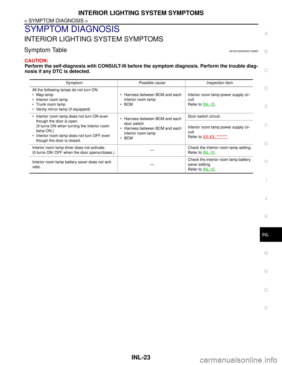
Symptom TableINFOID:0000000001728883
CAUTION:
Perform the self-diagnosis with CONSULT-III before the symptom diagnosis. Perform the trouble diag-
nosis if any DTC is detected.
Symptom Possible cause Inspection item
All the following lamps do not turn ON.
Map lamp
Interior room lamp
Trunk room lamp
Vanity mirror lamp (if equipped) Harness between BCM and each
interior room lamp
BCMInterior room lamp power supply cir-
cuit
Refer to INL-15
.
Interior room lamp does not turn ON even
though the door is open.
(It turns ON when turning the interior room
lamp ON.)
Interior room lamp does not turn OFF even
though the door is closed. Harness between BCM and each
door switch
Harness between BCM and each
interior room lamp
BCMDoor switch circuit.
Interior room lamp power supply cir-
cuit
Refer to XX-XX, "*****"
.
Interior room lamp timer does not activate.
(It turns ON/ OFF when the door opens/closes.)—Check the interior room lamp setting.
Refer to INL-10
.
Interior room lamp battery saver does not acti-
vate.—Check the interior room lamp battery
saver setting.
Refer to INL-12
.
Page 3675 of 5883

INL-24
< PRECAUTION >
PRECAUTIONS
PRECAUTION
PRECAUTIONS
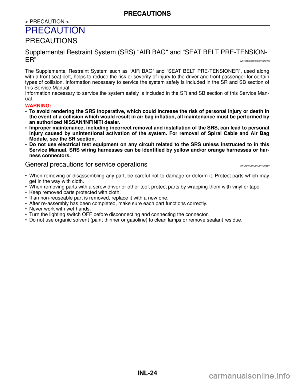
Supplemental Restraint System (SRS) "AIR BAG" and "SEAT BELT PRE-TENSION-
ER"
INFOID:0000000001726696
The Supplemental Restraint System such as “AIR BAG” and “SEAT BELT PRE-TENSIONER”, used along
with a front seat belt, helps to reduce the risk or severity of injury to the driver and front passenger for certain
types of collision. Information necessary to service the system safely is included in the SR and SB section of
this Service Manual.
Information necessary to service the system safely is included in the SR and SB section of this Service Man-
ual.
WARNING:
• To avoid rendering the SRS inoperative, which could increase the risk of personal injury or death in
the event of a collision which would result in air bag inflation, all maintenance must be performed by
an authorized NISSAN/INFINITI dealer.
Improper maintenance, including incorrect removal and installation of the SRS, can lead to personal
injury caused by unintentional activation of the system. For removal of Spiral Cable and Air Bag
Module, see the SR section.
Do not use electrical test equipment on any circuit related to the SRS unless instructed to in this
Service Manual. SRS wiring harnesses can be identified by yellow and/or orange harnesses or har-
ness connectors.
General precautions for service operationsINFOID:0000000001726697
When removing or disassembling any part, be careful not to damage or deform it. Protect parts which may
get in the way with cloth.
When removing parts with a screw driver or other tool, protect parts by wrapping them with vinyl or tape.
Keep removed parts protected with cloth.
If an non-reuseable part is removed, replace it with a new one.
After re-assembly has been completed, make sure each part functions correctly.
Never work with wet hands.
Turn the lighting switch OFF before disconnecting and connecting the connector.
Do not use organic solvent (paint thinner or gasoline) to clean lamps or remove sealant residue.