2007 NISSAN TIIDA Driver controls
[x] Cancel search: Driver controlsPage 3652 of 5883

INL-1
DRIVER CONTROLS
C
D
E
F
G
H
I
J
K
M
SECTION INL
A
B
INL
N
O
P
CONTENTS
INTERIOR LIGHTING SYSTEM
BASIC INSPECTION ....................................2
DIAGNOSIS AND REPAIR WORKFLOW ..........2
Work Flow .................................................................2
FUNCTION DIAGNOSIS ...............................5
INTERIOR ROOM LAMP CONTROL SYSTEM
.....
5
System Diagram ........................................................5
System Description ...................................................5
Component Parts Location ........................................6
Component Description ............................................6
ILLUMINATION CONTROL SYSTEM .................8
System Diagram ........................................................8
System Description ...................................................8
Component Parts Location ........................................8
Component Description .............................................9
DIAGNOSIS SYSTEM (BCM) ............................10
COMMON ITEM .........................................................10
COMMON ITEM : CONSULT-III Function (BCM -
COMMON ITEM) .....................................................
10
INT LAMP ..................................................................10
INT LAMP : CONSULT-III Function (BCM - INT
LAMP) .....................................................................
10
BATTERY SAVER .....................................................12
BATTERY SAVER : CONSULT-III Function (BCM
- BATTERY SAVER) ...............................................
12
COMPONENT DIAGNOSIS .........................14
POWER SUPPLY AND GROUND CIRCUIT ......14
BCM ...........................................................................14
BCM : Diagnosis Procedure ....................................14
INTERIOR ROOM LAMP POWER SUPPLY
CIRCUIT ............................................................
15
Description ...............................................................15
Component Function Check ....................................15
Diagnosis Procedure ...............................................15
INTERIOR ROOM LAMP CONTROL SYSTEM
...
17
Wiring Diagram - INTERIOR ROOM LAMP - ..........17
ILLUMINATION .................................................20
Wiring Diagram - ILLUMINATION - .........................20
ECU DIAGNOSIS .........................................22
BCM (BODY CONTROL MODULE) .................22
Description ...............................................................22
SYMPTOM DIAGNOSIS ..............................23
INTERIOR LIGHTING SYSTEM SYMPTOMS ...23
Symptom Table .......................................................23
PRECAUTION ..............................................24
PRECAUTIONS .................................................24
Supplemental Restraint System (SRS) "AIR BAG"
and "SEAT BELT PRE-TENSIONER" .....................
24
General precautions for service operations .............24
ON-VEHICLE REPAIR .................................25
INTERIOR ROOM LAMP ..................................25
Removal and Installation .........................................25
SERVICE DATA AND SPECIFICATIONS
(SDS) ............................................................
28
SERVICE DATA AND SPECIFICATIONS
(SDS) .................................................................
28
Bulb Specifications ..................................................28
Page 3657 of 5883
INL-6
< FUNCTION DIAGNOSIS >
INTERIOR ROOM LAMP CONTROL SYSTEM
a signal is received from an Intelligent Key or main power window and door lock/unlock switch, or when the
front door LH lock assembly (key cylinder switch) is locked or unlocked
a door is opened or closed
the Intelligent Key is removed from or inserted into the key slot.
The Interior lamp battery saver control time period can be changed with the function setting of CONSULT-III.
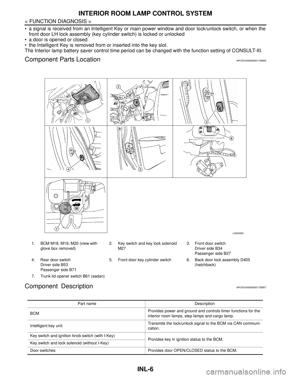
Component Parts LocationINFOID:0000000001728856
Component DescriptionINFOID:0000000001728857
1. BCM M18, M19, M20 (view with
glove box removed)2. Key switch and key lock solenoid
M273. Front door switch
Driver side B34
Passenger side B27
4. Rear door switch
Driver side B53
Passenger side B715. Front door key cylinder switch 6. Back door lock assembly D405
(hatchback)
7. Trunk lid opener switch B61 (sedan)
LIIA2942E
Part name Description
BCMProvides power and ground and controls timer functions for the
interior room lamps, step lamps and cargo lamp.
Intelligent key unitTransmits the lock/unlock signal to the BCM via CAN communi-
cation.
Key switch and ignition knob switch (with I-Key)
Provides key in ignition status to the BCM.
Key switch and lock solenoid (without I-Key)
Door switches Provides door OPEN/CLOSED status to the BCM.
Page 4299 of 5883
MIR-1
DRIVER CONTROLS
C
D
E
F
G
H
I
J
K
M
SECTION MIR
A
B
MIR
N
O
P
CONTENTS
MIRRORS
PRECAUTION ...............................................2
PRECAUTIONS ...................................................2
Precaution for Supplemental Restraint System
(SRS) "AIR BAG" and "SEAT BELT PRE-TEN-
SIONER" ...................................................................
2
COMPONENT DIAGNOSIS ..........................3
DOOR MIRROR ...................................................3
Wiring Diagram — Position Adjustment (LHD) — ......3
Wiring Diagram — Position Adjustment (RHD) — ......4
Wiring Diagram — Power Fold System (LHD) — .....5
Wiring Diagram — Power Fold System (RHD) — .....6
REMOVAL AND INSTALLATION ................7
DOOR MIRROR .................................................7
Removal and Installation ..........................................7
Disassembly and Assembly ......................................8
INSIDE MIRROR ................................................9
Removal and Installation ..........................................9
Page 4468 of 5883
POWER WINDOW SYSTEM
PWC-7
< FUNCTION DIAGNOSIS >
C
D
E
F
G
H
I
J
L
MA
B
PWC
N
O
P
POWER WINDOW OPERATION
Power window system is operable during the retained power operation timer after turning ignition switch ON
and OFF.
Main power window and door lock/unlock switch can open/close all windows.
Front & rear power window switches can open/close the corresponding windows.
POWER WINDOW AUTO-OPERATION (FRONT DRIVER SIDE)
AUTO UP/DOWN operation can be performed when main power window and door lock/unlock switch turns
to AUTO.
Encoder continues detecting the movement of power window motor and transmits to main power window
and door lock/unlock switch as the encoder pulse signal while power window motor is operating.
Main power window and door lock/unlock switch reads the changes of encoder signal and stops AUTO oper-
ation when door glass is at fully opened/closed position.
Power window motor is operable in case encoder is malfunctioning.
RETAINED POWER OPERATION
Retained power operation is an additional power supply function that enables power window system to oper-
ate during the 45 seconds even when ignition switch is turned OFF
Retained power function cancel conditions Front door CLOSE (door switch OFF)→OPEN (door switch ON).
When ignition switch is ON.
When timer time passes (45 seconds).
POWER WINDOW LOCK
Ground circuit inside main power window and door lock/unlock switch shuts off when power window lock
switch is ON. This inhibits power window switch operation except with the main power window and door lock/
unlock switch.
ANTI-PINCH OPERATION (FRONT DRIVER SIDE)
Pinch foreign material in the door glass during AUTO-UP operation,and it is the anti-pinch function that low-
ers the door glass 150 mm (5.9 in.) or 2 seconds when detected.
Encoder continues detecting the movement of power window motor and transmits to main power window
and door lock/unlock switch as the encoder pulse signal while power window motor is operating.
Resistance is applied to the power window motor rotation that changes the frequency of encoder pulse sig-
nal if foreign material is trapped in the door glass.
Power window switch controls to lower the window glass for 150 mm (5.9 in.) or 2 seconds after it detects
encoder pulse signal frequency change.
OPERATION CONDITION
When door glass AUTO-UP operation is performed (anti-pinch function does not operate just before the door
glass closes and is fully closed)
NOTE:
Depending on environment and driving conditions, if a similar impact or load is applied to the door glass, it
may lower.
Item Input signal to front power window
switch (passenger side) & rear power
window switch (LH & RH)Front power window switch
(passenger side) & rear power
window switch (LH & RH) func-
tionActuator
Front power window
switch (passenger
side)Front power window motor (passen-
ger side) UP/DOWN signal
Power window controlFront power window motor
(passenger side)
Rear power window
switch (LH & RH)Rear power window motor (LH & RH)
UP/DOWN signalRear power window motor (LH
& RH)
Page 4469 of 5883
PWC-8
< FUNCTION DIAGNOSIS >
POWER WINDOW SYSTEM
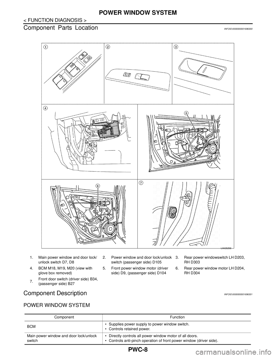
Component Parts Location
INFOID:0000000001696300
Component DescriptionINFOID:0000000001696301
POWER WINDOW SYSTEM
LIIA2529E
1. Main power window and door lock/
unlock switch D7, D82. Power window and door lock/unlock
switch (passenger side) D1053. Rear power windowswitch LH D203,
RH D303
4. BCM M18, M19, M20 (view with
glove box removed)5. Front power window motor (driver
side) D9, (passenger side) D1046. Rear power window motor LH D204,
RH D304
7.Front door switch (driver side) B34,
(passenger side) B27
Component Function
BCM Supplies power supply to power window switch.
Controls retained power.
Main power window and door lock/unlock
switch Directly controls all power window motor of all doors.
Controls anti-pinch operation of front power window (driver side).
Page 4470 of 5883
POWER WINDOW SYSTEM
PWC-9
< FUNCTION DIAGNOSIS >
C
D
E
F
G
H
I
J
L
MA
B
PWC
N
O
P
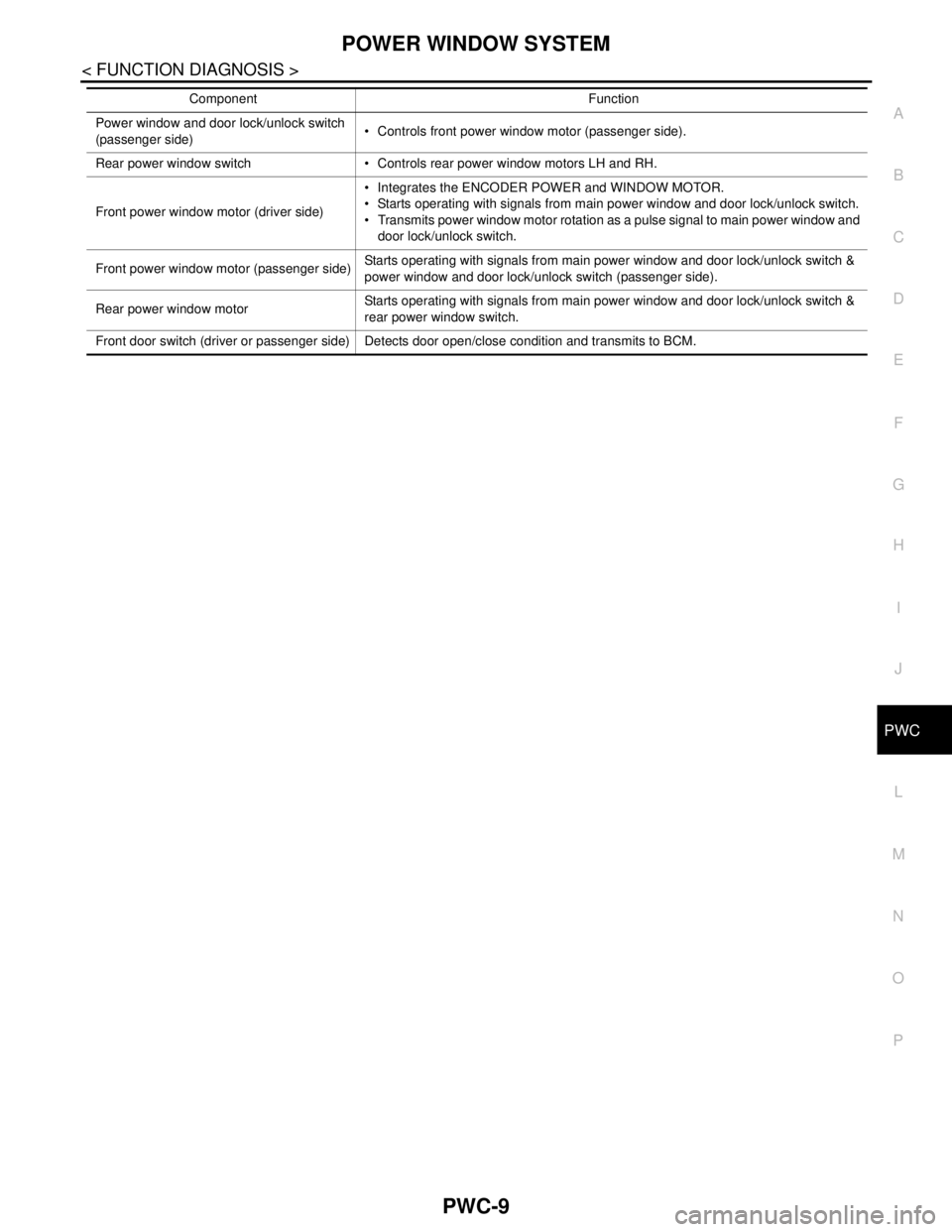
Power window and door lock/unlock switch
(passenger side) Controls front power window motor (passenger side).
Rear power window switch Controls rear power window motors LH and RH.
Front power window motor (driver side) Integrates the ENCODER POWER and WINDOW MOTOR.
Starts operating with signals from main power window and door lock/unlock switch.
Transmits power window motor rotation as a pulse signal to main power window and
door lock/unlock switch.
Front power window motor (passenger side)Starts operating with signals from main power window and door lock/unlock switch &
power window and door lock/unlock switch (passenger side).
Rear power window motorStarts operating with signals from main power window and door lock/unlock switch &
rear power window switch.
Front door switch (driver or passenger side) Detects door open/close condition and transmits to BCM.Component Function
Page 5803 of 5883
WW-1
DRIVER CONTROLS
C
D
E
F
G
H
I
J
K
M
SECTION WW
A
B
WW
N
O
P
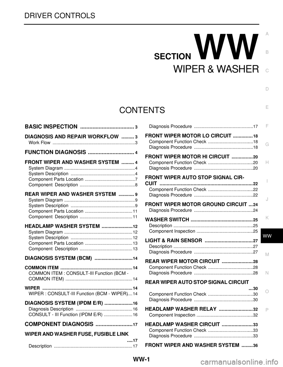
CONTENTS
WIPER & WASHER
BASIC INSPECTION ....................................3
DIAGNOSIS AND REPAIR WORKFLOW ..........3
Work Flow .................................................................3
FUNCTION DIAGNOSIS ...............................4
FRONT WIPER AND WASHER SYSTEM ..........4
System Diagram ........................................................4
System Description ...................................................4
Component Parts Location ........................................7
Component Description ............................................8
REAR WIPER AND WASHER SYSTEM ............9
System Diagram ........................................................9
System Description ...................................................9
Component Parts Location ......................................11
Component Description ..........................................11
HEADLAMP WASHER SYSTEM .......................12
System Diagram ......................................................12
System Description .................................................12
Component Parts Location ......................................13
Component Description ..........................................13
DIAGNOSIS SYSTEM (BCM) ............................14
COMMON ITEM .........................................................14
COMMON ITEM : CONSULT-III Function (BCM -
COMMON ITEM) .....................................................
14
WIPER .......................................................................14
WIPER : CONSULT-III Function (BCM - WIPER) ....14
DIAGNOSIS SYSTEM (IPDM E/R) .....................16
Diagnosis Description .............................................16
CONSULT - III Function (IPDM E/R) .......................16
COMPONENT DIAGNOSIS .........................17
WIPER AND WASHER FUSE, FUSIBLE LINK
....
17
Description ..............................................................17
Diagnosis Procedure ...............................................17
FRONT WIPER MOTOR LO CIRCUIT ..............18
Component Function Check ....................................18
Diagnosis Procedure ...............................................18
FRONT WIPER MOTOR HI CIRCUIT ...............20
Component Function Check ....................................20
Diagnosis Procedure ...............................................20
FRONT WIPER AUTO STOP SIGNAL CIR-
CUIT ..................................................................
22
Component Function Check ....................................22
Diagnosis Procedure ...............................................22
FRONT WIPER MOTOR GROUND CIRCUIT ...24
Diagnosis Procedure ...............................................24
WASHER SWITCH ............................................25
Description ...............................................................25
Component Inspection .............................................25
LIGHT & RAIN SENSOR ..................................27
Description ...............................................................27
Diagnosis Procedure ...............................................27
REAR WIPER MOTOR CIRCUIT ......................28
Component Function Check ....................................28
Diagnosis Procedure ...............................................28
REAR WIPER AUTO STOP SIGNAL CIRCUIT
...
30
Component Function Check ....................................30
Diagnosis Procedure ...............................................30
HEADLAMP WASHER RELAY ........................32
Component Inspection .............................................32
HEADLAMP WASHER CIRCUIT ......................33
Component Function Check ....................................33
Diagnosis Procedure ...............................................33
FRONT WIPER AND WASHER SYSTEM ........36