2007 NISSAN TIIDA Cooling
[x] Cancel search: CoolingPage 4283 of 5883

ENGINE MAINTENANCE (K9K)
MA-43
< ON-VEHICLE MAINTENANCE >
C
D
E
F
G
H
I
J
K
L
MB
MAN
OA
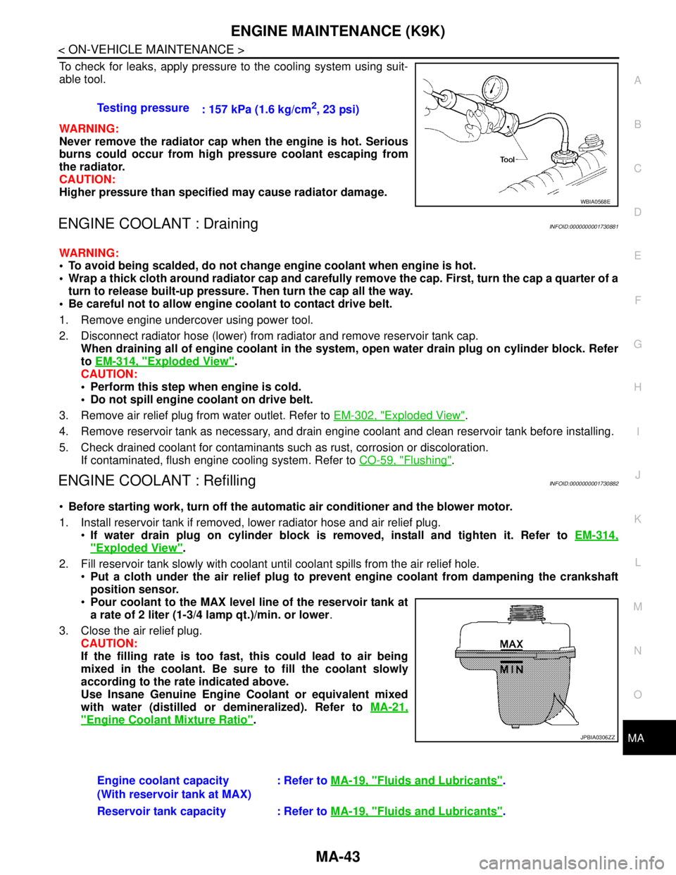
To check for leaks, apply pressure to the cooling system using suit-
able tool.
WARNING:
Never remove the radiator cap when the engine is hot. Serious
burns could occur from high pressure coolant escaping from
the radiator.
CAUTION:
Higher pressure than specified may cause radiator damage.
ENGINE COOLANT : DrainingINFOID:0000000001730881
WARNING:
To avoid being scalded, do not change engine coolant when engine is hot.
Wrap a thick cloth around radiator cap and carefully remove the cap. First, turn the cap a quarter of a
turn to release built-up pressure. Then turn the cap all the way.
Be careful not to allow engine coolant to contact drive belt.
1. Remove engine undercover using power tool.
2. Disconnect radiator hose (lower) from radiator and remove reservoir tank cap.
When draining all of engine coolant in the system, open water drain plug on cylinder block. Refer
to EM-314, "
Exploded View".
CAUTION:
Perform this step when engine is cold.
Do not spill engine coolant on drive belt.
3. Remove air relief plug from water outlet. Refer to EM-302, "
Exploded View".
4. Remove reservoir tank as necessary, and drain engine coolant and clean reservoir tank before installing.
5. Check drained coolant for contaminants such as rust, corrosion or discoloration.
If contaminated, flush engine cooling system. Refer to CO-59, "
Flushing".
ENGINE COOLANT : RefillingINFOID:0000000001730882
Before starting work, turn off the automatic air conditioner and the blower motor.
1. Install reservoir tank if removed, lower radiator hose and air relief plug.
If water drain plug on cylinder block is removed, install and tighten it. Refer to EM-314,
"Exploded View".
2. Fill reservoir tank slowly with coolant until coolant spills from the air relief hole.
Put a cloth under the air relief plug to prevent engine coolant from dampening the crankshaft
position sensor.
Pour coolant to the MAX level line of the reservoir tank at
a rate of 2 liter (1-3/4 lamp qt.)/min. or lower.
3. Close the air relief plug.
CAUTION:
If the filling rate is too fast, this could lead to air being
mixed in the coolant. Be sure to fill the coolant slowly
according to the rate indicated above.
Use Insane Genuine Engine Coolant or equivalent mixed
with water (distilled or demineralized). Refer to MA-21,
"Engine Coolant Mixture Ratio". Testing pressure
: 157 kPa (1.6 kg/cm
2, 23 psi)
WBIA0568E
JPBIA0306ZZ
Engine coolant capacity
(With reservoir tank at MAX): Refer to MA-19, "Fluids and Lubricants".
Reservoir tank capacity : Refer to MA-19, "
Fluids and Lubricants".
Page 4284 of 5883

MA-44
< ON-VEHICLE MAINTENANCE >
ENGINE MAINTENANCE (K9K)
4. Start engine without closing reservoir tank cap and keep engine racing at 1,500 rpm for about 2-3 minutes.
If necessary, pour engine coolant up to MAX level.
If coolant overflows reservoir tank hole, install filler cap.
Watch engine coolant temperature gauge so as not overheat the engine.
WARNING:
Be careful not to be scaled with hot engine coolant or vacuum pump when operating.
Radiator fan blade can start at any time and cause personal injuries.
5. Turn off the engine and loosen air relief plug until coolant spills from air relief hole.
6. Close the air relief plug and run the engine at 2,000 rpm until the upper hose becomes hot and radiator
fan operates. Leave the engine running approximately 5 minutes at idle speed and check for sound of
coolant flow while running engine from idle up to 3,000 rpm.
Sound may be noticeable at heater water cock.
7. If sound is heard, bleed air from cooling system by repeating steps 4 to 6 until coolant level no longer
drops.
Check the radiator lower hose for any signs of leakage.
8. Turn off the engine and let it cool down.
Cool down using a fan to reduce the time.
9. After cooling period, loosen the air relief plug and check if coolant spills from the air relief hole. if not,
remove the air relief plug until the coolant spills, and then close the relief air plug. Bleed air from cooling
system by repeating steps 6 to 10 until the coolant spills immediately.
10. Check the engine coolant level when engine is cool and refill to MAX level line if the level is lower.
Clean excess coolant from engine.
11. Check that the reservoir tank cap is tightened.
ENGINE COOLANT : FlushingINFOID:0000000001730883
1. Install reservoir tank if removed.
If water drain plug on cylinder block is removed, close and tighten it. Refer to EM-314, "
Exploded
View".
2. Fill reservoir tank with water until water spills from the air relief hole, then close air relief plug. Reinstall
reservoir tank cap.
3. Run engine and warm it up to normal operating temperature.
4. Rev engine two or three times under no-load.
5. Stop engine and wait until it cools down.
6. Drain water.
7. Repeat steps 1 through 6 until clear water begins to drain from radiator.
8. Blow compressed air into cooling circuit through the reservoir tank valve hole to drain all the water.
RADIATOR
RADIATOR : Checking Radiator CapINFOID:0000000001730884
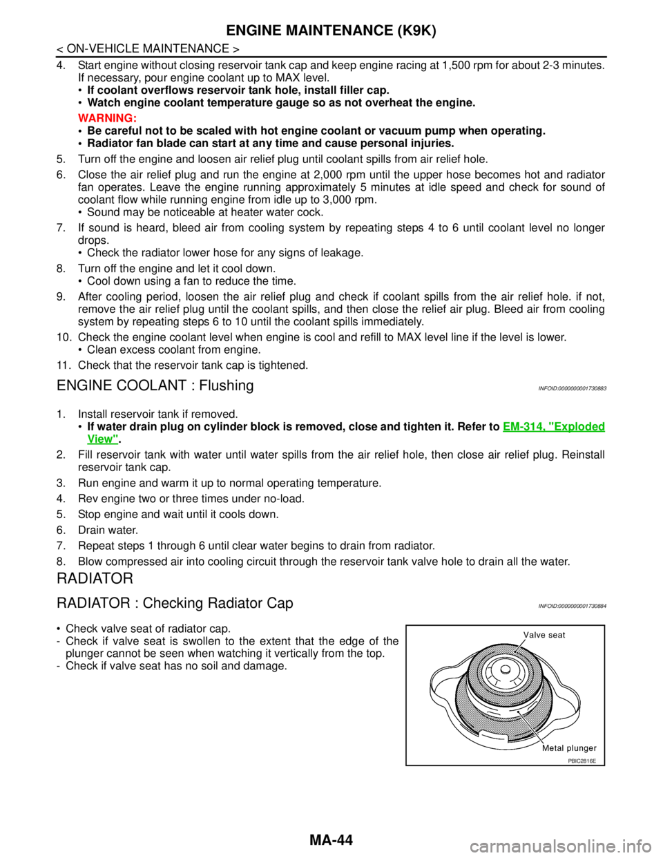
Check valve seat of radiator cap.
- Check if valve seat is swollen to the extent that the edge of the
plunger cannot be seen when watching it vertically from the top.
- Check if valve seat has no soil and damage.
PBIC2816E
Page 4285 of 5883

ENGINE MAINTENANCE (K9K)
MA-45
< ON-VEHICLE MAINTENANCE >
C
D
E
F
G
H
I
J
K
L
MB
MAN
OA
Pull negative-pressure valve to open it, and make sure that it is
completely closed when released.
- Make sure that there is no dirt or damage on the valve seat of radi-
ator cap negative-pressure valve.
- Make sure that the valve operates properly in the opening and
closing conditions.
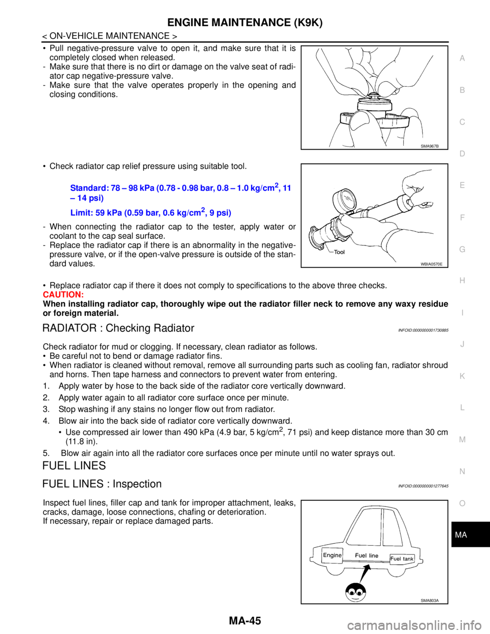
Check radiator cap relief pressure using suitable tool.
- When connecting the radiator cap to the tester, apply water or
coolant to the cap seal surface.
- Replace the radiator cap if there is an abnormality in the negative-
pressure valve, or if the open-valve pressure is outside of the stan-
dard values.
Replace radiator cap if there it does not comply to specifications to the above three checks.
CAUTION:
When installing radiator cap, thoroughly wipe out the radiator filler neck to remove any waxy residue
or foreign material.
RADIATOR : Checking RadiatorINFOID:0000000001730885
Check radiator for mud or clogging. If necessary, clean radiator as follows.
Be careful not to bend or damage radiator fins.
When radiator is cleaned without removal, remove all surrounding parts such as cooling fan, radiator shroud
and horns. Then tape harness and connectors to prevent water from entering.
1. Apply water by hose to the back side of the radiator core vertically downward.
2. Apply water again to all radiator core surface once per minute.
3. Stop washing if any stains no longer flow out from radiator.
4. Blow air into the back side of radiator core vertically downward.
Use compressed air lower than 490 kPa (4.9 bar, 5 kg/cm
2, 71 psi) and keep distance more than 30 cm
(11.8 in).
5. Blow air again into all the radiator core surfaces once per minute until no water sprays out.
FUEL LINES
FUEL LINES : InspectionINFOID:0000000001277645
Inspect fuel lines, filler cap and tank for improper attachment, leaks,
cracks, damage, loose connections, chafing or deterioration.
If necessary, repair or replace damaged parts.
SMA967B
Standard: 78 – 98 kPa (0.78 - 0.98 bar, 0.8 – 1.0 kg/cm2, 11
– 14 psi)
Limit: 59 kPa (0.59 bar, 0.6 kg/cm
2, 9 psi)
WBIA0570E
SMA803A
Page 4385 of 5883

MWI-78
< ECU DIAGNOSIS >
IPDM E/R (INTELLIGENT POWER DISTRIBUTION MODULE ENGINE ROOM)
Te r m i n a lWire
colorSignal nameSignal
input/
outputMeasuring condition
Reference value
(Approx.) Ignition
switchOperation or condition
1 R Battery power supply Input OFF — Battery voltage
2 G Battery power supply Input OFF — Battery voltage
3 Y ECM Relay Output —Ignition switch ON or START Battery voltage
Ignition switch OFF or ACC 0V
4 G ECM relay Output —Ignition switch ON or START Battery voltage
Ignition switch OFF or ACC 0V
6GRDaytime light relay
controlInput ON Daytime light system active. Less than battery voltage
Daytime light system inactive. Battery voltage
7 G ECM relay control Input —Ignition switch ON or START 0V
Ignition switch OFF or ACC Battery voltage
8GThrottle control motor
relayOutput —Ignition switch ON or START Battery voltage
Ignition switch OFF or ACC 0V
11 W A/C compressor OutputON or
STARTA/C switch ON or defrost A/C
switchBattery voltage
A/C switch OFF or defrost A/C
switch0V
12 OIgnition switch sup-
plied powerInput —OFF or ACC 0V
ON or START Battery voltage
14BR
(M/T)
R
(A/T)Fuse 49 Output —Ignition switch ON or START Battery voltage
Ignition switch OFF or ACC 0V
15 V Fuse 50 Output —Ignition switch ON or START Battery voltage
Ignition switch OFF or ACC 0V
16 SB Fuse 51 Output —Ignition switch ON or START Battery voltage
Ignition switch OFF or ACC 0V
19 R Starter motor Output START — Battery voltage
20L
(with
A/C)
LG
(with-
out A/
C)Cooling fan relay-1 Output —Conditions correct for cooling
fan low operation.Battery voltage
Conditions not correct for
cooling fan low operation.0V
21 WIgnition switch START
signalInput START — Battery voltage
22 G Battery power supply Input — — Battery voltage
23 L Cooling fan relay-2 Input —Conditions correct for cooling
fan high operationBattery voltage
Conditions not correct for
cooling fan high operation0V
24 Y Cooling fan relay-3 Output —Conditions correct for cooling
fan high operationBattery voltage
Conditions not correct for
cooling fan high operation0V
27 BR
Tail lamp relay (park-
ing lamps)Output — Lighting switch in 2nd position Battery voltage
Page 4392 of 5883

MWI
IPDM E/R (INTELLIGENT POWER DISTRIBUTION MODULE ENGINE ROOM)
MWI-85
< ECU DIAGNOSIS >
C
D
E
F
G
H
I
J
K
L
MB A
O
P If No CAN Communication Is Available With BCM
IGNITION RELAY MALFUNCTION DETECTION FUNCTION
IPDM E/R monitors the voltage at the contact circuit and excitation coil circuit of the ignition relay inside it.
IPDM E/R judges the ignition relay error if the voltage differs between the contact circuit and the excitation
coil circuit.
If the ignition relay cannot turn OFF due to contact seizure, it activates the tail lamp relay for 10 minutes to
alert the user to the ignition relay malfunction when the ignition switch is turned OFF.
NOTE:
The tail lamp turns OFF when the ignition switch is turned ON.
FRONT WIPER CONTROL
IPDM E/R detects front wiper stop position by a front wiper auto stop signal.
When a front wiper auto stop signal is in the conditions listed below, IPDM E/R stops power supply to wiper
after repeating a front wiper 10 second activation and 20 second stop five times.
NOTE:
This operation status can be confirmed on the IPDM E/R “DATA MONITOR” that displays “Block” for the item
“WIP PROT” while the wiper is stopped.
STARTER MOTOR PROTECTION FUNCTION
IPDM E/R turns OFF the starter control relay to protect the starter motor when the starter control relay remains
active for 90 seconds.
Control part Fail-safe in operation
Cooling fan Turns ON the cooling fan relay when the ignition switch is turned ON
Turns OFF the cooling fan relay when the ignition switch is turned OFF
Control part Fail-safe in operation
Headlamp Turns ON the headlamp low relay when the ignition switch is turned ON
Turns OFF the headlamp low relay when the ignition switch is turned OFF
Headlamp high relay OFF
Parking lamps
License plate lamps
Tail lamps Turns ON the tail lamp relay when the ignition switch is turned ON
Turns OFF the tail lamp relay when the ignition switch is turned OFF
Front wiper The status just before activation of fail-safe control is maintained until the ignition
switch is turned OFF while the front wiper is operating at LO or HI speed.
The wiper is operated at LO speed until the ignition switch is turned OFF if the fail-
safe control is activated while the front wiper is set in the INT mode and the front wiper
motor is operating.
Rear window defogger Rear window defogger relay OFF
A/C compressor A/C relay OFF
Front fog lamps Front fog lamp relay OFF
Ignition switch Ignition relay Tail lamp relay
ON ON —
OFF OFF —
Ignition switch Front wiper switch Auto stop signal
ONOFFFront wiper stop position signal cannot be
input 10 seconds.
ON The signal does not change for 10 seconds.
Page 4418 of 5883
![NISSAN TIIDA 2007 Service Repair Manual PCS-4
< FUNCTION DIAGNOSIS >[IPDM E/R]
RELAY CONTROL SYSTEM
System Description
INFOID:0000000001697580
IPDM E/R activates the internal control circuit to perform the relay ON-OFF control according to NISSAN TIIDA 2007 Service Repair Manual PCS-4
< FUNCTION DIAGNOSIS >[IPDM E/R]
RELAY CONTROL SYSTEM
System Description
INFOID:0000000001697580
IPDM E/R activates the internal control circuit to perform the relay ON-OFF control according to](/manual-img/5/57395/w960_57395-4417.png)
PCS-4
< FUNCTION DIAGNOSIS >[IPDM E/R]
RELAY CONTROL SYSTEM
System Description
INFOID:0000000001697580
IPDM E/R activates the internal control circuit to perform the relay ON-OFF control according to the input sig-
nals from various sensors and the request signals received from control units via CAN communication.
CAUTION:
IPDM E/R integrated relays cannot be removed.
Control relay Input/output Transmit unit Control partReference
page
Front fog lamp relay Front fog lamp request signal BCM (CAN) Front fog lampsEXL-19
• Headlamp high relay
Headlamp low relay High beam request signal
Low beam request signalBCM (CAN) Headlamp high
Headlamp lowEXL-8
EXL-10
Tail lamp relay Position light request signal BCM (CAN)Parking lamps
License plate lamps
Tail lamps
Illumination systemEXL-24
Front wiper relay
Front wiper high relayFront wiper request signal BCM (CAN) Front wiper motorWW-4
Rear window defogger re-
layRear window defogger re-
quest signalBCM (CAN) Rear window defoggerDEF-6
A/C relay A/C request signalBCM (CAN)
ECM (CAN)A/C compressorHAC-11
Starter relay Ignition switch START signal TCM Starter motorSTR-6
Cooling fan relay Cooling fan request signal ECM (CAN) Cooling fan relayCO-4
ECM relay ECM relay control signal ECM (CAN) ECM relayEC-124
Throttle control motor relayThrottle control motor control
signalECM (CAN)Throttle control motor re-
layEC-38
Fuel pump relay Fuel pump request signal ECM (CAN) Fuel pumpEC-38
Ignition relay Ignition switch ON signal Ignition switch Ignition relayEC-47
Page 4420 of 5883
![NISSAN TIIDA 2007 Service Repair Manual PCS-6
< FUNCTION DIAGNOSIS >[IPDM E/R]
POWER CONTROL SYSTEM
POWER CONTROL SYSTEM
System DiagramINFOID:0000000001697582
System DescriptionINFOID:0000000001697583
COOLING FAN CONTROL
IPDM E/R controls t NISSAN TIIDA 2007 Service Repair Manual PCS-6
< FUNCTION DIAGNOSIS >[IPDM E/R]
POWER CONTROL SYSTEM
POWER CONTROL SYSTEM
System DiagramINFOID:0000000001697582
System DescriptionINFOID:0000000001697583
COOLING FAN CONTROL
IPDM E/R controls t](/manual-img/5/57395/w960_57395-4419.png)
PCS-6
< FUNCTION DIAGNOSIS >[IPDM E/R]
POWER CONTROL SYSTEM
POWER CONTROL SYSTEM
System DiagramINFOID:0000000001697582
System DescriptionINFOID:0000000001697583
COOLING FAN CONTROL
IPDM E/R controls the cooling fan according to the status of the cooling fan speed request signal received
from ECM via CAN communication. Refer to LAN-13, "
System Description".
ALMIA0111GB
Page 4424 of 5883
![NISSAN TIIDA 2007 Service Repair Manual PCS-10
< FUNCTION DIAGNOSIS >[IPDM E/R]
DIAGNOSIS SYSTEM (IPDM E/R)
DIAGNOSIS SYSTEM (IPDM E/R)
Diagnosis DescriptionINFOID:0000000001697589
AUTO ACTIVE TEST
Description
In auto active test mode, the NISSAN TIIDA 2007 Service Repair Manual PCS-10
< FUNCTION DIAGNOSIS >[IPDM E/R]
DIAGNOSIS SYSTEM (IPDM E/R)
DIAGNOSIS SYSTEM (IPDM E/R)
Diagnosis DescriptionINFOID:0000000001697589
AUTO ACTIVE TEST
Description
In auto active test mode, the](/manual-img/5/57395/w960_57395-4423.png)
PCS-10
< FUNCTION DIAGNOSIS >[IPDM E/R]
DIAGNOSIS SYSTEM (IPDM E/R)
DIAGNOSIS SYSTEM (IPDM E/R)
Diagnosis DescriptionINFOID:0000000001697589
AUTO ACTIVE TEST
Description
In auto active test mode, the IPDM E/R sends a drive signal to the following systems to check their operation.
Oil pressure low/coolant pressure high warning indicator
Oil pressure gauge
Rear window defogger
Front wipers
Tail, license and parking lamps
Front fog lamps
Headlamps (Hi, Lo)
A/C compressor (magnetic clutch)
Cooling fan
Operation Procedure
1. Close the hood and front door RH, and lift the wiper arms from the windshield (to prevent windshield dam-
age due to wiper operation).
NOTE:
When auto active test is performed with hood opened, sprinkle water on windshield before hand.
2. Turn ignition switch OFF.
3. Turn the ignition switch ON and, within 20 seconds, press the front door switch LH 10 times. Then turn the
ignition switch OFF.
4. Turn the ignition switch ON within 10 seconds. After that the horn sounds once and the auto active test
starts.
5. After a series of the following operations is repeated 3 times, auto active test is completed.
NOTE:
When auto active test mode has to be cancelled halfway through test, turn ignition switch OFF.
CAUTION:
• If auto active test mode cannot be actuated, check door switch system. Refer to DLK-65, "
DRIVER
SIDE : Description" (with Intelligent Key system), DLK-499, "DRIVER SIDE : Description" (without
Intelligent Key system).
Do not start the engine.
Inspection in Auto Active Test Mode