2007 NISSAN TIIDA fuel type
[x] Cancel search: fuel typePage 2834 of 5883
![NISSAN TIIDA 2007 Service Repair Manual CAMSHAFT
EM-187
< ON-VEHICLE REPAIR >[MR18DE]
C
D
E
F
G
H
I
J
K
L
MA
EM
N
P O
Fuel tube and fuel injector assembly; Refer to EM-162.
Front cover, timing chain and related parts; Refer to EM-176
.](/manual-img/5/57395/w960_57395-2833.png "NISSAN TIIDA 2007 Service Repair Manual CAMSHAFT
EM-187
< ON-VEHICLE REPAIR >[MR18DE]
C
D
E
F
G
H
I
J
K
L
MA
EM
N
P O
Fuel tube and fuel injector assembly; Refer to EM-162.
Front cover, timing chain and related parts; Refer to EM-176
.")
CAMSHAFT
EM-187
< ON-VEHICLE REPAIR >[MR18DE]
C
D
E
F
G
H
I
J
K
L
MA
EM
N
P O
Fuel tube and fuel injector assembly; Refer to EM-162.
Front cover, timing chain and related parts; Refer to EM-176
.
7. Remove camshaft position sensor (PHASE) from camshaft bracket.
CAUTION:
Handle carefully to avoid dropping and shocks.
Never disassemble.
Never allow metal powder to adhere to magnetic part at sensor tip.
Never place sensor in a location where it is exposed to magnetism.
8. Put the matching mark (A) on the camshaft sprocket (INT) (2)
and the camshaft bracket (1) as shown.
NOTE:
It prevents the knock pin of the camshaft (INT) from engaging
with the incorrect pin hole when installing the camshaft sprocket
(INT).
9. Remove camshaft sprockets (INT) (1) and (EXH) (2).
Secure hexagonal part (A) of camshaft with a wrench. Loosen
camshaft sprocket bolts and remove camshaft sprocket.
CAUTION:
Never rotate crankshaft or camshaft while timing chain
is removed. It causes interference between valve and
piston.
Never loosen the bolts with securing anything other
than the camshaft hexagonal part or with tensioning the
timing chain.
10. Loosen bolts in reverse order as shown.
11. Cut liquid gasket by prying the position ( ) shown, and then
remove the camshaft bracket.
CAUTION:
Be careful not to damage the mating surface.
A more adhesive liquid gasket is applied compared to pre-
vious types when shipped, so it should not be forced off
the position not specified.
12. Remove camshafts.
: Engine front
PBIC3992J
PBIC3454J
: Engine front
PBIC3176J
: Engine front
PBIC3358J
Page 2855 of 5883
![NISSAN TIIDA 2007 Service Repair Manual EM-208
< REMOVAL AND INSTALLATION >[MR18DE]
ENGINE ASSEMBLY
Always use the support point specified for lifting.
Use either 2-pole lift type or separate type lift as best you can. If board-on type](/manual-img/5/57395/w960_57395-2854.png "NISSAN TIIDA 2007 Service Repair Manual EM-208
< REMOVAL AND INSTALLATION >[MR18DE]
ENGINE ASSEMBLY
Always use the support point specified for lifting.
Use either 2-pole lift type or separate type lift as best you can. If board-on type")
EM-208
< REMOVAL AND INSTALLATION >[MR18DE]
ENGINE ASSEMBLY
Always use the support point specified for lifting.
Use either 2-pole lift type or separate type lift as best you can. If board-on type is used for unavoid-
able reasons, support at the rear axle jacking point with a transmission jack or similar tool before
starting work, in preparation for the backward shift of center of gravity.
For supporting points for lifting and jacking point at rear axle, refer to GI-48, "
Garage Jack and
Safety Stand and 2-Pole Lift".
REMOVAL
Remove the engine and the transaxle assembly from the vehicle downward. Separate the engine and the tran-
saxle.
1. Remove engine undercover
2. Drain engine coolant from radiator. Refer to CO-35, "
Changing Engine Coolant".
CAUTION:
Perform this step when the engine is cold.
Do not spill engine coolant on drive belt.
3. Remove front fender protector (RH and LH); Refer to EXT-22, "
Removal and Installation".
4. Remove exhaust front tube; Refer to EX-10, "
Component".
5. Remove drive shafts (LH and RH) from steering knuckle. Refer to FA X - 7 , "
Removal and Installation".
6. Remove transaxle joint bolts which pierce at oil pan (upper) lower rear side. Refer to EM-207, "
Compo-
nent".
7. Remove rear torque rod (1).
8. Remove hood assembly. Refer to DLK-214, "
Removal and Installation".
9. Remove cowl top cover and cowl top extension assembly. Refer to EXT-20, "
Removal and Installation".
10. Release fuel pressure. Refer to EC-1035, "
Inspection".
11. Remove battery and battery tray; Refer to PG-6, "
Removal and Installation".
12. Remove drive belt; Refer to EM-142, "
Component".
13. Remove air duct and air cleaner case assembly; Refer to EM-154
.
14. Remove cooling fan assembly.
15. Remove radiator hose (upper and lower). Refer to CO-40, "
Component".
16. Disconnect all connections of engine harness around the engine mounting insulator (LH), and then tem-
porarily secure the engine harness into the engine side.
CAUTION:
Protect connectors using a resin bag to protect against foreign materials during the operation.
17. Disconnect fuel feed hose at engine side. Refer to EM-162, "
Component".
18. Disconnect heater hoses, and install plugs them to prevent engine coolant from draining. Refer to CO-47,
"Component".
19. Disconnect control cable from transaxle. Refer to TM-674, "
Exploded View".
20. Remove ground cable at transaxle side.
21. Remove ground cable between front cover and vehicle.
22. Remove generator. Refer to CHG-29, "
Removal and Installation".
23. Remove A/C compressor with piping connected from the engine. Temporarily secure it on the vehicle side
with a rope to avoid putting load on it. Refer to HA-32, "
Removal and Installation of Compressor -
MR18DE".
LBIA0460E
Page 3084 of 5883
FRONT FOG LAMP
EXL-83
< ON-VEHICLE MAINTENANCE >
C
D
E
F
G
H
I
J
K
MA
B
EXL
N
O
P
FRONT FOG LAMP
Aiming AdjustmentINFOID:0000000001529283
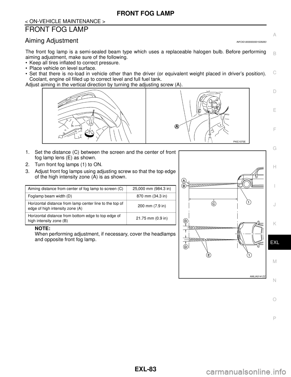
The front fog lamp is a semi-sealed beam type which uses a replaceable halogen bulb. Before performing
aiming adjustment, make sure of the following.
Keep all tires inflated to correct pressure.
Place vehicle on level surface.
Set that there is no-load in vehicle other than the driver (or equivalent weight placed in driver’s position).
Coolant, engine oil filled up to correct level and full fuel tank.
Adjust aiming in the vertical direction by turning the adjusting screw (A).
1. Set the distance (C) between the screen and the center of front
fog lamp lens (E) as shown.
2. Turn front fog lamps (1) to ON.
3. Adjust front fog lamps using adjusting screw so that the top edge
of the high intensity zone (A) is as shown.
NOTE:
When performing adjustment, if necessary, cover the headlamps
and opposite front fog lamp.
PKIC1070E
Aiming distance from center of fog lamp to screen (C) 25,000 mm (984.3 in)
Foglamp beam width (D) 870 mm (34.3 in)
Horizontal distance from lamp center line to the top of
edge of high intensity zone (A)200 mm (7.9 in)
Horizontal distance from bottom edge to top edge of
high intensity zone (B)21.75 mm (0.9 in)
AWLIA0141ZZ
Page 3178 of 5883
FSU-2
< PRECAUTION >
PRECAUTIONS
PRECAUTION
PRECAUTIONS
Precaution for Supplemental Restraint System (SRS) "AIR BAG" and "SEAT BELT
PRE-TENSIONER"
INFOID:0000000001716875
The Supplemental Restraint System such as “AIR BAG” and “SEAT BELT PRE-TENSIONER”, used along
with a front seat belt, helps to reduce the risk or severity of injury to the driver and front passenger for certain
types of collision. This system includes seat belt switch inputs and dual stage front air bag modules. The SRS
system uses the seat belt switches to determine the front air bag deployment, and may only deploy one front
air bag, depending on the severity of a collision and whether the front occupants are belted or unbelted.
Information necessary to service the system safely is included in the SR and SB section of this Service Man-
ual.
WARNING:
• To avoid rendering the SRS inoperative, which could increase the risk of personal injury or death in
the event of a collision which would result in air bag inflation, all maintenance must be performed by
an authorized NISSAN/INFINITI dealer.
Improper maintenance, including incorrect removal and installation of the SRS, can lead to personal
injury caused by unintentional activation of the system. For removal of Spiral Cable and Air Bag
Module, see the SR section.
Do not use electrical test equipment on any circuit related to the SRS unless instructed to in this
Service Manual. SRS wiring harnesses can be identified by yellow and/or orange harnesses or har-
ness connectors.
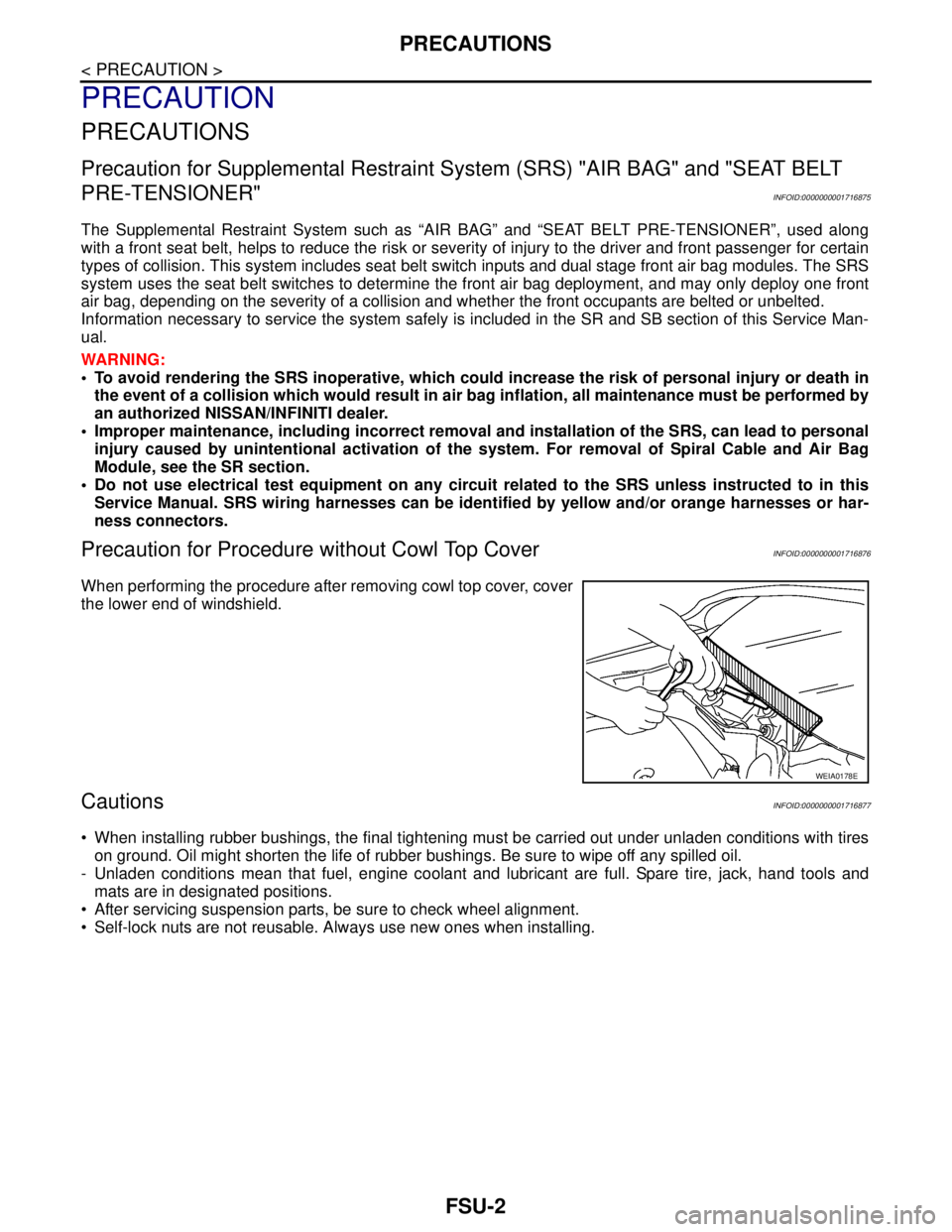
Precaution for Procedure without Cowl Top CoverINFOID:0000000001716876
When performing the procedure after removing cowl top cover, cover
the lower end of windshield.
CautionsINFOID:0000000001716877
When installing rubber bushings, the final tightening must be carried out under unladen conditions with tires
on ground. Oil might shorten the life of rubber bushings. Be sure to wipe off any spilled oil.
- Unladen conditions mean that fuel, engine coolant and lubricant are full. Spare tire, jack, hand tools and
mats are in designated positions.
After servicing suspension parts, be sure to check wheel alignment.
Self-lock nuts are not reusable. Always use new ones when installing.
WEIA0178E
Page 3182 of 5883
FSU-6
< ON-VEHICLE MAINTENANCE >
FRONT SUSPENSION ASSEMBLY
ON-VEHICLE MAINTENANCE
FRONT SUSPENSION ASSEMBLY
On-Vehicle Inspection and ServiceINFOID:0000000001716890
Make sure the mounting conditions (looseness, back lash) of each component and component conditions
(wear, damage) are normal.
INSPECTION OF LOWER BALL JOINT END PLAY
1. Set front wheels in a straight-ahead position. Do not depress brake pedal.
2. Place an iron bar or similar tool between transverse link and steering knuckle.
3. Measure axial end play by prying it up and down.
CAUTION:
Be careful not to damage ball joint boot. Do not damage the installation position by applying
excessive force.
STRUT INSPECTION
Check for oil leakage, damage and replace as necessary.
Wheel Alignment InspectionINFOID:0000000001716891
PRELIMINARY INSPECTION
WARNING:
Always adjust the alignment with the vehicle on a flat surface.
NOTE:
If alignment is out of specification, inspect and replace any damaged or worn rear suspension parts before
making any adjustments.
1. Check and adjust the wheel alignment with the vehicle under unladen conditions. “Unladen conditions”
means that the fuel, coolant, and lubricant are full; and that the spare tire, jack, hand tools and mats are in
their designated positions.
2. Check the tires for incorrect air pressure and excessive wear.
3. Check the wheels for run out and damage. Refer to WT-5, "
Inspection" .
4. Check the wheel bearing axial end play. Refer to FA X - 5 , "
On-Vehicle Inspection and Service" .
5. Check the shock absorbers for leaks or damage.
6. Check each mounting point of the suspension components for any excessive looseness or damage.
7. Check each link, arm, and the suspension member for any damage.
8. Check the vehicle height. Refer to FSU-18, "
Wheelarch Height (Unladen*)" .
GENERAL INFORMATION AND RECOMMENDATIONS
1. A Four-Wheel Thrust Alignment should be performed.
This type of alignment is recommended for any NISSAN vehicle.
The four-wheel “thrust” process helps ensure that the vehicle is properly aligned and the steering wheel
is centered.
The alignment machine itself should be capable of accepting any NISSAN vehicle.
The alignment machine should be checked to ensure that it is level.
2. Make sure the alignment machine is properly calibrated.
Your alignment machine should be regularly calibrated in order to give correct information.
Check with the manufacturer of your specific alignment machine for their recommended Service/Cali-
bration Schedule.
THE ALIGNMENT PROCESS
IMPORTANT: Use only the alignment specifications listed in this Service Manual. Refer to FSU-17, "Wheel
Alignment (Unladen*)" .
1. When displaying the alignment settings, many alignment machines use “indicators”: (Green/red, plus or
minus, Go/No Go). Do NOT use these indicators. Axial end play : 0 mm (0 in)
Page 3773 of 5883
![NISSAN TIIDA 2007 Service Repair Manual LAN
CAN COMMUNICATION SYSTEM
LAN-33
< FUNCTION DIAGNOSIS >[CAN]
C
D
E
F
G
H
I
J
K
L B A
O
P N
Check CAN system type from the vehicle shape and equipment.
CAN Communication Signal ChartINFOID:000000000](/manual-img/5/57395/w960_57395-3772.png "NISSAN TIIDA 2007 Service Repair Manual LAN
CAN COMMUNICATION SYSTEM
LAN-33
< FUNCTION DIAGNOSIS >[CAN]
C
D
E
F
G
H
I
J
K
L B A
O
P N
Check CAN system type from the vehicle shape and equipment.
CAN Communication Signal ChartINFOID:000000000")
LAN
CAN COMMUNICATION SYSTEM
LAN-33
< FUNCTION DIAGNOSIS >[CAN]
C
D
E
F
G
H
I
J
K
L B A
O
P N
Check CAN system type from the vehicle shape and equipment.
CAN Communication Signal ChartINFOID:0000000001162801
Refer to LAN-21, "How to Use CAN Communication Signal Chart" for how to use CAN communication signal
chart.
NOTE:
Refer to LAN-27, "
Abbreviation List" for the abbreviations of the connecting units.
T: Transmit R: Receive
ALMIA0068GB
Signal name/Connecting unitECM
BCM
EPS
I-KEY
M&A
STRG
AV
ABS
TCM
IPDM-E
A/C compressor request signal TR
Accelerator pedal position signal T
R
*1R
ASCD CRUISE lamp signal T R
ASCD status signal T R
Closed throttle position signal T R
Cooling fan speed request signal TR
Engine coolant temperature signal T R R
Engine speed signal T R R R
R
*1R
Engine status signal T R R R
Fuel consumption monitor signal T R R
Glow indicator signal
*2TR
Malfunctioning indicator lamp signal (×2
*2)TR
Wide open throttle signal T R
A/C switch signal R T
Blower fan motor switch signal
*3RT
Page 4247 of 5883
PERIODIC MAINTENANCE
MA-7
< ON-VEHICLE MAINTENANCE >
C
D
E
F
G
H
I
J
K
L
MB
MAN
OA
PERIODIC MAINTENANCE
Periodic MaintenanceINFOID:0000000001277598
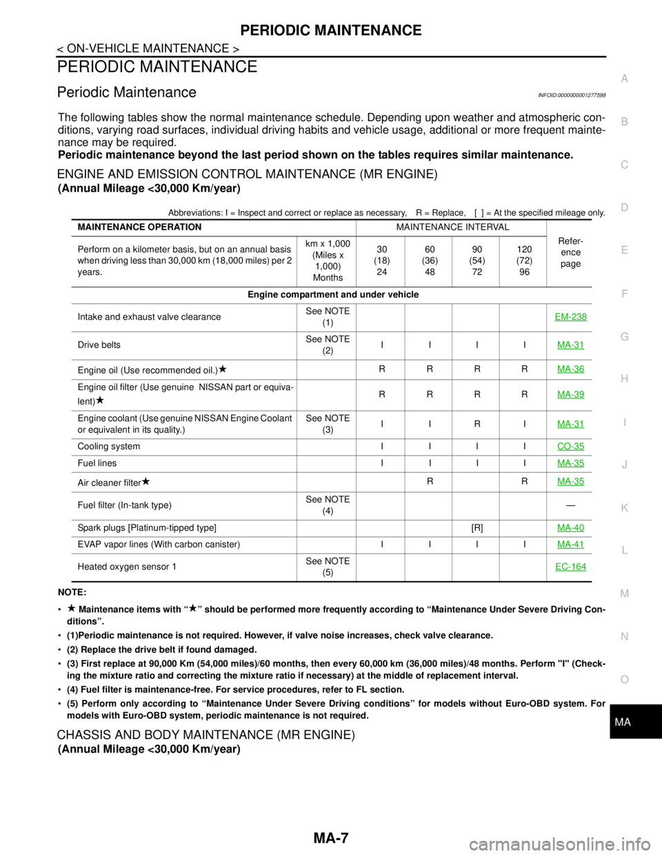
The following tables show the normal maintenance schedule. Depending upon weather and atmospheric con-
ditions, varying road surfaces, individual driving habits and vehicle usage, additional or more frequent mainte-
nance may be required.
Periodic maintenance beyond the last period shown on the tables requires similar maintenance.
ENGINE AND EMISSION CONTROL MAINTENANCE (MR ENGINE)
(Annual Mileage <30,000 Km/year)
Abbreviations: I = Inspect and correct or replace as necessary, R = Replace, [ ] = At the specified mileage only.
NOTE:
Maintenance items with “ ” should be performed more frequently according to “Maintenance Under Severe Driving Con-
ditions”.
(1)Periodic maintenance is not required. However, if valve noise increases, check valve clearance.
(2) Replace the drive belt if found damaged.
(3) First replace at 90,000 Km (54,000 miles)/60 months, then every 60,000 km (36,000 miles)/48 months. Perform "I" (Check-
ing the mixture ratio and correcting the mixture ratio if necessary) at the middle of replacement interval.
(4) Fuel filter is maintenance-free. For service procedures, refer to FL section.
(5) Perform only according to “Maintenance Under Severe Driving conditions” for models without Euro-OBD system. For
models with Euro-OBD system, periodic maintenance is not required.
CHASSIS AND BODY MAINTENANCE (MR ENGINE)
(Annual Mileage <30,000 Km/year)
MAINTENANCE OPERATIONMAINTENANCE INTERVAL
Refer-
ence
page Perform on a kilometer basis, but on an annual basis
when driving less than 30,000 km (18,000 miles) per 2
years.km x 1,000
(Miles x
1,000)
Months30
(18)
2460
(36)
4890
(54)
72120
(72)
96
Engine compartment and under vehicle
Intake and exhaust valve clearanceSee NOTE
(1)EM-238
Drive beltsSee NOTE
(2)IIIIMA-31
Engine oil (Use recommended oil.)RRRRMA-36
Engine oil filter (Use genuine NISSAN part or equiva-
lent)RRRRMA-39
Engine coolant (Use genuine NISSAN Engine Coolant
or equivalent in its quality.)See NOTE
(3)IIRIMA-31
Cooling system I I I ICO-35
Fuel lines I I I IMA-35
Air cleaner filterRRMA-35
Fuel filter (In-tank type)See NOTE
(4)—
Spark plugs [Platinum-tipped type] [R]MA-40
EVAP vapor lines (With carbon canister) I I I IMA-41
Heated oxygen sensor 1See NOTE
(5)EC-164
Page 4249 of 5883
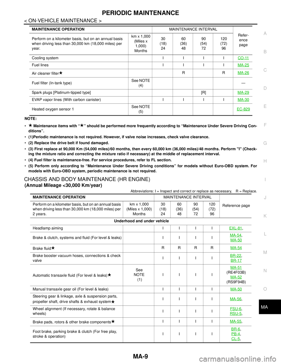
PERIODIC MAINTENANCE
MA-9
< ON-VEHICLE MAINTENANCE >
C
D
E
F
G
H
I
J
K
L
MB
MAN
OA
NOTE:
Maintenance items with “ ” should be performed more frequently according to “Maintenance Under Severe Driving Con-
ditions”.
(1)Periodic maintenance is not required. However, if valve noise increases, check valve clearance.
(2) Replace the drive belt if found damaged.
(3) First replace at 90,000 Km (54,000 miles)/60 months, then every 60,000 km (36,000 miles)/48 months. Perform "I" (Check-
ing the mixture ratio and correcting the mixture ratio if necessary) at the middle of replacement interval.
(4) Fuel filter is maintenance-free. For service procedures, refer to FL section.
(5) Perform only according to “Maintenance Under Severe Driving conditions” for models without Euro-OBD system. For
models with Euro-OBD system, periodic maintenance is not required.
CHASSIS AND BODY MAINTENANCE (HR ENGINE)
(Annual Mileage <30,000 Km/year)
Abbreviations: I = Inspect and correct or replace as necessary, R = Replace.
Cooling system I I I ICO-11
Fuel lines I I I IMA-25
Air cleaner filterRRMA-26
Fuel filter (In-tank type)See NOTE
(4)—
Spark plugs [Platinum-tipped type] [R]MA-29
EVAP vapor lines (With carbon canister) I I I IMA-30
Heated oxygen sensor 1See NOTE
(5)EC-829
MAINTENANCE OPERATIONMAINTENANCE INTERVAL
Refer-
ence
page Perform on a kilometer basis, but on an annual basis
when driving less than 30,000 km (18,000 miles) per
year.km x 1,000
(Miles x
1,000)
Months30
(18)
2460
(36)
4890
(54)
72120
(72)
96
MAINTENANCE OPERATIONMAINTENANCE INTERVAL
Reference page Perform on a kilometer basis, but on an annual basis
when driving less than 30,000 km (18,000 miles) per
2 years.km x 1,000
(Miles x 1,000)
Months30
(18)
2460
(36)
4890
(54)
72120
(72)
96
Underhood and under vehicle
Headlamp aiming IIIIEXL-81
,
Brake & clutch, systems and fluid (For level & leaks) IIIIMA-54
,
MA-50
Brake fluidRRRRMA-54
Brake booster vacuum hoses, connections & check
valveIIIIBR-22,
BR-17
Automatic transaxle fluid (For level & leaks)See
NOTE
(1)IIIIMA-51(RE4F03B)
MA-52
(RS9F94B)
Manual transaxle gear oil (For level & leaks) IIIIMA-50
Steering gear & linkage, axle & suspension parts,
propeller shaft, drive shafts & exhaust systemIIIIMA-56,
Wheel alignment (If necessary, rotate & balance
wheels)IIIIFSU-6
,
RSU-5
,
Brake pads, rotors & other brake componentsIIIIMA-55
,
Foot brake, parking brake & clutch (For free play,
stroke & operation)IIIIBR-6
,
PB-4
,
CL-5
,