2007 NISSAN TIIDA fuel type
[x] Cancel search: fuel typePage 4253 of 5883
PERIODIC MAINTENANCE
MA-13
< ON-VEHICLE MAINTENANCE >
C
D
E
F
G
H
I
J
K
L
MB
MAN
OA
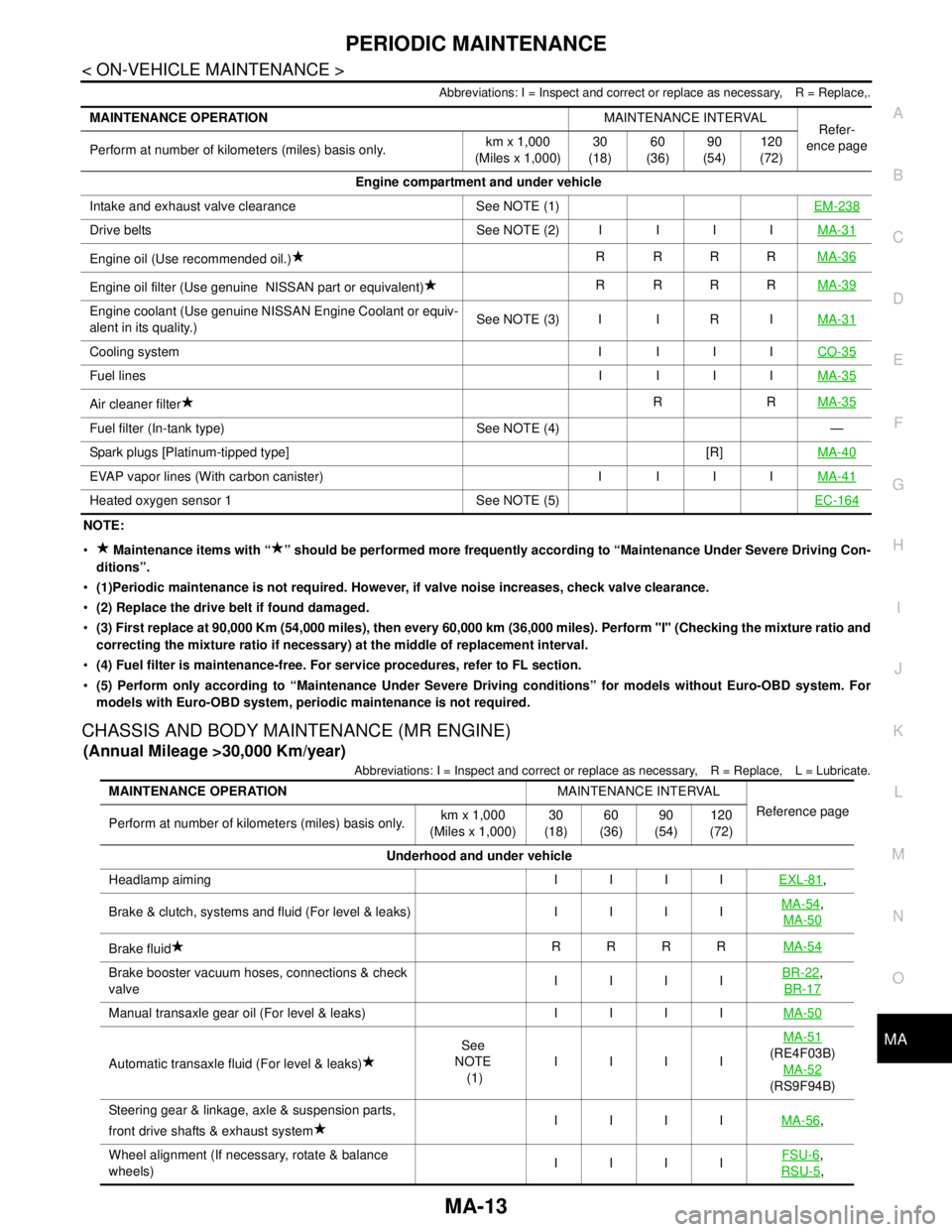
Abbreviations: I = Inspect and correct or replace as necessary, R = Replace,.
NOTE:
Maintenance items with “ ” should be performed more frequently according to “Maintenance Under Severe Driving Con-
ditions”.
(1)Periodic maintenance is not required. However, if valve noise increases, check valve clearance.
(2) Replace the drive belt if found damaged.
(3) First replace at 90,000 Km (54,000 miles), then every 60,000 km (36,000 miles). Perform "I" (Checking the mixture ratio and
correcting the mixture ratio if necessary) at the middle of replacement interval.
(4) Fuel filter is maintenance-free. For service procedures, refer to FL section.
(5) Perform only according to “Maintenance Under Severe Driving conditions” for models without Euro-OBD system. For
models with Euro-OBD system, periodic maintenance is not required.
CHASSIS AND BODY MAINTENANCE (MR ENGINE)
(Annual Mileage >30,000 Km/year)
Abbreviations: I = Inspect and correct or replace as necessary, R = Replace, L = Lubricate.
MAINTENANCE OPERATIONMAINTENANCE INTERVAL
Refer-
ence page
Perform at number of kilometers (miles) basis only.km x 1,000
(Miles x 1,000)30
(18)60
(36)90
(54)120
(72)
Engine compartment and under vehicle
Intake and exhaust valve clearance See NOTE (1)EM-238
Drive belts See NOTE (2) I I I IMA-31
Engine oil (Use recommended oil.)RRRRMA-36
Engine oil filter (Use genuine NISSAN part or equivalent)RRRRMA-39
Engine coolant (Use genuine NISSAN Engine Coolant or equiv-
alent in its quality.)See NOTE (3) I I R IMA-31
Cooling system I I I ICO-35
Fuel linesI IIIMA-35
Air cleaner filterRRMA-35
Fuel filter (In-tank type) See NOTE (4) —
Spark plugs [Platinum-tipped type] [R]MA-40
EVAP vapor lines (With carbon canister) I I I IMA-41
Heated oxygen sensor 1 See NOTE (5)EC-164
MAINTENANCE OPERATIONMAINTENANCE INTERVAL
Reference page
Perform at number of kilometers (miles) basis only.km x 1,000
(Miles x 1,000)30
(18)60
(36)90
(54)120
(72)
Underhood and under vehicle
Headlamp aiming I I I IEXL-81
,
Brake & clutch, systems and fluid (For level & leaks) I I I IMA-54
,
MA-50
Brake fluidRRRRMA-54
Brake booster vacuum hoses, connections & check
valveIIIIBR-22,
BR-17
Manual transaxle gear oil (For level & leaks) I I I IMA-50
Automatic transaxle fluid (For level & leaks)See
NOTE
(1)IIIIMA-51(RE4F03B)
MA-52
(RS9F94B)
Steering gear & linkage, axle & suspension parts,
front drive shafts & exhaust systemIIIIMA-56
,
Wheel alignment (If necessary, rotate & balance
wheels)IIIIFSU-6
,
RSU-5
,
Page 4254 of 5883
MA-14
< ON-VEHICLE MAINTENANCE >
PERIODIC MAINTENANCE
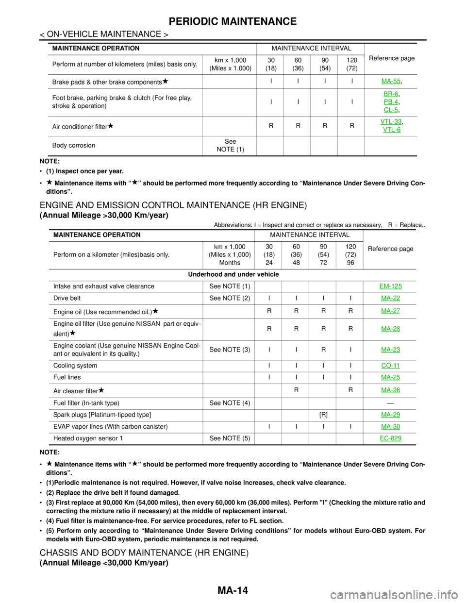
NOTE:
(1) Inspect once per year.
Maintenance items with “ ” should be performed more frequently according to “Maintenance Under Severe Driving Con-
ditions”.
ENGINE AND EMISSION CONTROL MAINTENANCE (HR ENGINE)
(Annual Mileage >30,000 Km/year)
Abbreviations: I = Inspect and correct or replace as necessary, R = Replace,.
NOTE:
Maintenance items with “ ” should be performed more frequently according to “Maintenance Under Severe Driving Con-
ditions”.
(1)Periodic maintenance is not required. However, if valve noise increases, check valve clearance.
(2) Replace the drive belt if found damaged.
(3) First replace at 90,000 Km (54,000 miles), then every 60,000 km (36,000 miles). Perform "I" (Checking the mixture ratio and
correcting the mixture ratio if necessary) at the middle of replacement interval.
(4) Fuel filter is maintenance-free. For service procedures, refer to FL section.
(5) Perform only according to “Maintenance Under Severe Driving conditions” for models without Euro-OBD system. For
models with Euro-OBD system, periodic maintenance is not required.
CHASSIS AND BODY MAINTENANCE (HR ENGINE)
(Annual Mileage <30,000 Km/year)
Brake pads & other brake componentsIIIIMA-55,
Foot brake, parking brake & clutch (For free play,
stroke & operation)IIIIBR-6
,
PB-4
,
CL-5
,
Air conditioner filterRRRRVTL-33
,
VTL-6
Body corrosionSee
NOTE (1) MAINTENANCE OPERATIONMAINTENANCE INTERVAL
Reference page
Perform at number of kilometers (miles) basis only.km x 1,000
(Miles x 1,000)30
(18)60
(36)90
(54)120
(72)
MAINTENANCE OPERATIONMAINTENANCE INTERVAL
Reference page
Perform on a kilometer (miles)basis only.km x 1,000
(Miles x 1,000)
Months30
(18)
2460
(36)
4890
(54)
72120
(72)
96
Underhood and under vehicle
Intake and exhaust valve clearance See NOTE (1)EM-125
Drive belt See NOTE (2)IIIIMA-22
Engine oil (Use recommended oil.)RRRRMA-27
Engine oil filter (Use genuine NISSAN part or equiv-
alent)RRRRMA-28
Engine coolant (Use genuine NISSAN Engine Cool-
ant or equivalent in its quality.)See NOTE (3) I I R IMA-23
Cooling system IIIICO-11
Fuel lines IIIIMA-25
Air cleaner filterRRMA-26
Fuel filter (In-tank type) See NOTE (4) —
Spark plugs [Platinum-tipped type] [R]MA-29
EVAP vapor lines (With carbon canister) IIIIMA-30
Heated oxygen sensor 1 See NOTE (5)EC-829
Page 4328 of 5883
MWI
DIAGNOSIS SYSTEM (METER)
MWI-21
< FUNCTION DIAGNOSIS >
C
D
E
F
G
H
I
J
K
L
MB A
O
P
DIAGNOSIS SYSTEM (METER)
Diagnosis DescriptionINFOID:0000000001374681
SELF-DIAGNOSIS MODE
Self-diagnosis can check for continuity between meter control circuit and each meter (speedometer, tachom-
eter and fuel gauge).
Self-diagnosis can check for odo/trip meter and information display segment, low-fuel level warning lamp,
low water temperature indicator lamp, and high water temperature warning lamp.
NOTE:
This combination meter has no capability to perform on-board data checking and CONSULT type active tests
as seen in other Nissan combination meters. For additional combination meter diagnostic functions refer to
MWI-22, "
CONSULT-III Function (METER/M&A)".
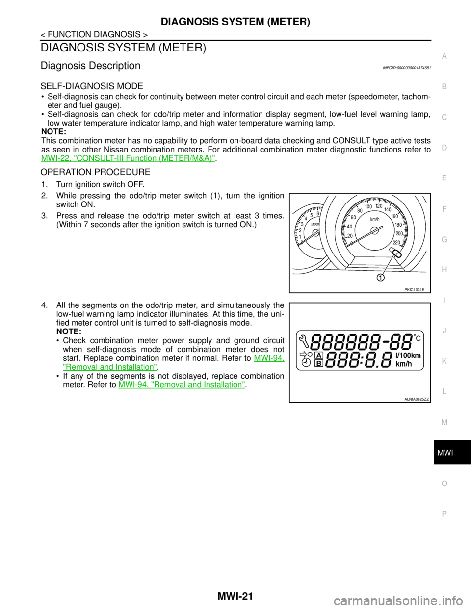
OPERATION PROCEDURE
1. Turn ignition switch OFF.
2. While pressing the odo/trip meter switch (1), turn the ignition
switch ON.
3. Press and release the odo/trip meter switch at least 3 times.
(Within 7 seconds after the ignition switch is turned ON.)
4. All the segments on the odo/trip meter, and simultaneously the
low-fuel warning lamp indicator illuminates. At this time, the uni-
fied meter control unit is turned to self-diagnosis mode.
NOTE:
Check combination meter power supply and ground circuit
when self-diagnosis mode of combination meter does not
start. Replace combination meter if normal. Refer to MWI-94,
"Removal and Installation".
If any of the segments is not displayed, replace combination
meter. Refer to MWI-94, "
Removal and Installation".
PKIC1031E
ALNIA0625ZZ
Page 4530 of 5883
PRECAUTIONS
RAX-3
< PRECAUTION >
C
E
F
G
H
I
J
K
L
MA
B
RAX
N
O
P
PRECAUTION
PRECAUTIONS
Precaution for Supplemental Restraint System (SRS) "AIR BAG" and "SEAT BELT
PRE-TENSIONER"
INFOID:0000000001724594
The Supplemental Restraint System such as “AIR BAG” and “SEAT BELT PRE-TENSIONER”, used along
with a front seat belt, helps to reduce the risk or severity of injury to the driver and front passenger for certain
types of collision. Information necessary to service the system safely is included in the SR and SB section of
this Service Manual.
WARNING:
• To avoid rendering the SRS inoperative, which could increase the risk of personal injury or death in
the event of a collision which would result in air bag inflation, all maintenance must be performed by
an authorized NISSAN/INFINITI dealer.
Improper maintenance, including incorrect removal and installation of the SRS, can lead to personal
injury caused by unintentional activation of the system. For removal of Spiral Cable and Air Bag
Module, see the SR section.
Do not use electrical test equipment on any circuit related to the SRS unless instructed to in this
Service Manual. SRS wiring harnesses can be identified by yellow and/or orange harnesses or har-
ness connectors.
PrecautionINFOID:0000000001724595
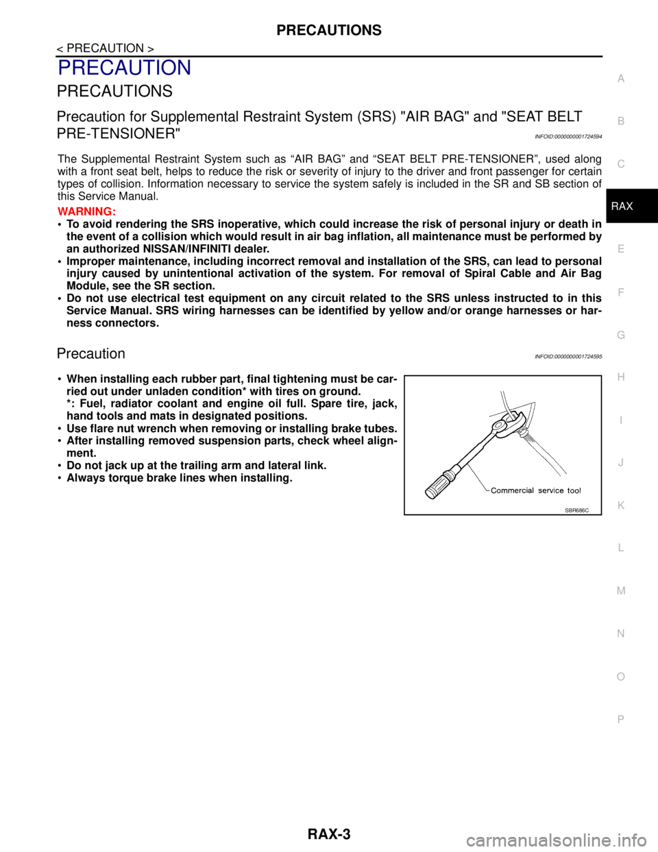
When installing each rubber part, final tightening must be car-
ried out under unladen condition* with tires on ground.
*: Fuel, radiator coolant and engine oil full. Spare tire, jack,
hand tools and mats in designated positions.
Use flare nut wrench when removing or installing brake tubes.
After installing removed suspension parts, check wheel align-
ment.
Do not jack up at the trailing arm and lateral link.
Always torque brake lines when installing.
SBR686C
Page 4575 of 5883

PRECAUTIONS
RSU-3
< PRECAUTION >
C
D
F
G
H
I
J
K
L
MA
B
RSU
N
O
P
PRECAUTION
PRECAUTIONS
Precaution for Supplemental Restraint System (SRS) "AIR BAG" and "SEAT BELT
PRE-TENSIONER"
INFOID:0000000001724583
The Supplemental Restraint System such as “AIR BAG” and “SEAT BELT PRE-TENSIONER”, used along
with a front seat belt, helps to reduce the risk or severity of injury to the driver and front passenger for certain
types of collision. This system includes seat belt switch inputs and dual stage front air bag modules. The SRS
system uses the seat belt switches to determine the front air bag deployment, and may only deploy one front
air bag, depending on the severity of a collision and whether the front occupants are belted or unbelted.
Information necessary to service the system safely is included in the SRS and SB section of this Service Man-
ual.
WARNING:
• To avoid rendering the SRS inoperative, which could increase the risk of personal injury or death in
the event of a collision which would result in air bag inflation, all maintenance must be performed by
an authorized NISSAN/INFINITI dealer.
Improper maintenance, including incorrect removal and installation of the SRS, can lead to personal
injury caused by unintentional activation of the system. For removal of Spiral Cable and Air Bag
Module, see the SRS section.
Do not use electrical test equipment on any circuit related to the SRS unless instructed to in this
Service Manual. SRS wiring harnesses can be identified by yellow and/or orange harnesses or har-
ness connectors.
Precaution for Rear SuspensionINFOID:0000000001724584
When installing the rubber bushings, the final tightening must be done under unladen condition and with the
tires on level ground. Oil will shorten the life of the rubber bushings, so wipe off any spilled oil immediately.
Unladen condition means the fuel tank, engine coolant and lubricants are at the full specification. The spare
tire, jack, hand tools, and mats are in their designated positions.
After installing suspension components, check the wheel alignment.
Caulking nuts are not reusable. Always use new caulking nuts for installation. New caulking nuts are pre-
oiled, do not apply any additional lubrication.
Page 4577 of 5883
REAR SUSPENSION ASSEMBLY
RSU-5
< ON-VEHICLE MAINTENANCE >
C
D
F
G
H
I
J
K
L
MA
B
RSU
N
O
P
ON-VEHICLE MAINTENANCE
REAR SUSPENSION ASSEMBLY
On-Vehicle Inspection and ServiceINFOID:0000000001724575
Make sure the mounting conditions (looseness, backlash) of each component and component conditions
(wear, damage) are within specifications.
SHOCK ABSORBER INSPECTION
Check shock absorber for oil leakage, damage and replace it if necessary.
Wheel AlignmentINFOID:0000000001724576
DESCRIPTION
Measure wheel alignment under unladen conditions.
NOTE:
“Unladen conditions” means that fuel, engine coolant, and lubricant are full. Spare tire, jack, hand tools and
mats are in designated positions.
PRELIMINARY
Check the following:
1. Tires for improper air pressure and wear.
2. Road wheels for runout. Refer to WT-5, "
Inspection" .
3. Wheel bearing axial end play. Refer to RAX-5, "
On-Vehicle Inspection and Service" .
4. Shock absorber operation.
5. Each mounting part of suspension for looseness and deformation.
6. Rear suspension beam for cracks, deformation, and other damage.
7. Vehicle height (posture).
GENERAL INFORMATION AND RECOMMENDATIONS
1. A Four-Wheel Thrust Alignment should be performed.
This type of alignment is recommended for any NISSAN vehicle.
The four-wheel “thrust” process helps ensure that the vehicle is properly aligned and the steering wheel
is centered.
The alignment machine itself should be capable of accepting any NISSAN vehicle.
The alignment machine should be checked to ensure that it is level.
2. Make sure the alignment machine is properly calibrated.
Your alignment machine should be regularly calibrated in order to give correct information.
Check with the manufacturer of your specific alignment machine for their recommended Service/Cali-
bration Schedule.
THE ALIGNMENT PROCESS
IMPORTANT: Use only the alignment specifications listed in this Service Manual. Refer to RSU-5, "Wheel
Alignment" .
1. When displaying the alignment settings, many alignment machines use “indicators”: (Green/red, plus or
minus, Go/No Go). Do NOT use these indicators.
The alignment specifications programmed into your alignment machine that operate these indicators
may not be correct.
This may result in an ERROR.
2. Some newer alignment machines are equipped with an optional “Rolling Compensation” method to “com-
pensate” the sensors (alignment targets or head units). Do NOT use this “Rolling Compensation”
method.
Use the “Jacking Compensation” method. After installing the alignment targets or head units, raise the
vehicle and rotate the wheels 1/2 turn both ways.
See Instructions in the alignment machine you are using for more information.
CAMBER INSPECTION
Page 4970 of 5883
![NISSAN TIIDA 2007 Service Repair Manual TM-24
< FUNCTION DIAGNOSIS >[TYPE 1 (4AT: RE4F03B)]
A/T CONTROL SYSTEM
The line pressure is temporarily reduced corresponding to a change
in engine torque when shifting gears (that is, when the shift](/manual-img/5/57395/w960_57395-4969.png "NISSAN TIIDA 2007 Service Repair Manual TM-24
< FUNCTION DIAGNOSIS >[TYPE 1 (4AT: RE4F03B)]
A/T CONTROL SYSTEM
The line pressure is temporarily reduced corresponding to a change
in engine torque when shifting gears (that is, when the shift")
TM-24
< FUNCTION DIAGNOSIS >[TYPE 1 (4AT: RE4F03B)]
A/T CONTROL SYSTEM
The line pressure is temporarily reduced corresponding to a change
in engine torque when shifting gears (that is, when the shift solenoid
valve is switched for clutch operation) to reduce shifting shock.
AT LOW FLUID TEMPERATURE
A/T fluid viscosity and frictional characteristics of the clutch facing change with A/T fluid temperature. Clutch
engaging or band-contacting pressure is compensated for, according to A/T fluid temperature, to stabilize
shifting quality.
The line pressure is reduced below 60°C (140°F) to prevent shift-
ing shock due to high viscosity of A/T fluid when temperature is
low.
Line pressure is increased to a maximum irrespective of the throt-
tle opening when A/T fluid temperature drops to −10°C (14°F). This
pressure rise is adopted to prevent a delay in clutch and brake
operation due to extreme drop of A/T fluid viscosity at low temper-
ature.
Shift ControlINFOID:0000000001694426
The shift is regulated entirely by electronic control to accommodate vehicle speed and varying engine opera-
tions. This is accomplished by electrical signals transmitted by the revolution sensor and the ECM (accelerator
pedal position sensor). This results in improved acceleration performance and fuel economy.
CONTROL OF SHIFT SOLENOID VALVES A AND B
The TCM activates shift solenoid valves A and B according to sig-
nals from the accelerator pedal position sensor and revolution sen-
sor to select the optimum gear position on the basis of the shift
schedule memorized in the TCM.
The shift solenoid valve performs simple ON-OFF operation. When
set to “ON”, the drain circuit closes and pilot pressure is applied to
the shift valve.
RELATION BETWEEN SHIFT SOLENOID VALVES A AND B AND GEAR POSITIONS
SCIA4828E
SCIA4829E
SCIA4830E
SAT008J
Page 4978 of 5883
![NISSAN TIIDA 2007 Service Repair Manual TM-32
< FUNCTION DIAGNOSIS >[TYPE 1 (4AT: RE4F03B)]
ON BOARD DIAGNOSTIC (OBD) SYSTEM
ON BOARD DIAGNOSTIC (OBD) SYSTEM
IntroductionINFOID:0000000001694433
A/T system has two self-diagnostic systems.
Th](/manual-img/5/57395/w960_57395-4977.png "NISSAN TIIDA 2007 Service Repair Manual TM-32
< FUNCTION DIAGNOSIS >[TYPE 1 (4AT: RE4F03B)]
ON BOARD DIAGNOSTIC (OBD) SYSTEM
ON BOARD DIAGNOSTIC (OBD) SYSTEM
IntroductionINFOID:0000000001694433
A/T system has two self-diagnostic systems.
Th")
TM-32
< FUNCTION DIAGNOSIS >[TYPE 1 (4AT: RE4F03B)]
ON BOARD DIAGNOSTIC (OBD) SYSTEM
ON BOARD DIAGNOSTIC (OBD) SYSTEM
IntroductionINFOID:0000000001694433
A/T system has two self-diagnostic systems.
The first is emission-related on board diagnostic system (OBD) performed by the TCM in combination with the
ECM. The malfunction is indicated by the MIL (malfunction indicator lamp) and is stored as a DTC in the ECM
memory but not the TCM memory.
The second is the TCM original self-diagnosis indicated by the OD OFF indicator lamp. The malfunction is
stored in the TCM memory. The detected items are overlapped with OBD self-diagnostic items. For detail,
refer to TM-35, "
CONSULT-III Function (TRANSMISSION)".
OBD Function for A/T SystemINFOID:0000000001694434
The ECM provides emission-related on board diagnostic (OBD) functions for the A/T system. One function is
to receive a signal from the TCM used with OBD-related parts of the A/T system. The signal is sent to the ECM
when a malfunction occurs in the corresponding OBD-related part. The other function is to indicate a diagnos-
tic result by means of the MIL (malfunction indicator lamp) on the instrument panel. Sensors, switches and
solenoid valves are used as sensing elements.
The MIL automatically illuminates in One or Two Trip Detection Logic when a malfunction is sensed in relation
to A/T system parts.
One or Two Trip Detection Logic of OBDINFOID:0000000001694435
ONE TRIP DETECTION LOGIC
If a malfunction is sensed during the first test drive, the MIL will illuminate and the malfunction will be stored in
the ECM memory as a DTC. The TCM is not provided with such a memory function.
TWO TRIP DETECTION LOGIC
When a malfunction is sensed during the first test drive, it is stored in the ECM memory as a 1st trip DTC
(diagnostic trouble code) or 1st trip freeze frame data. At this point, the MIL will not illuminate. — 1st trip
If the same malfunction as that experienced during the first test drive is sensed during the second test drive,
the MIL will illuminate. — 2nd trip
The “trip” in the “One or Two Trip Detection Logic” means a driving mode in which self-diagnosis is performed
during vehicle operation.
OBD Diagnostic Trouble Code (DTC)INFOID:0000000001694436
HOW TO READ DTC AND 1ST TRIP DTC
DTC and 1st trip DTC can be read by the following methods.
( with CONSULT-III or GST) CONSULT-III or GST (Generic Scan Tool) Examples: P0705, P0720 etc.
These DTC are prescribed by SAE J2012.
(CONSULT-III also displays the malfunctioning component or system.)
1st trip DTC No. is the same as DTC No.
Output of the diagnostic trouble code indicates that the indicated circuit has a malfunction. How-
ever, in case of the Mode II and GST, they do not indicate whether the malfunction is still occurring or
occurred in the past and returned to normal.
CONSULT-III can identify them as shown below, therefore, CONSULT-III (if available) is recom-
mended.
Freeze Frame Data and 1st Trip Freeze Frame Data
The ECM has a memory function, which stores the driving condition such as fuel system status, calculated
load value, engine coolant temperature, short term fuel trim, long term fuel trim, engine speed and vehicle
speed at the moment the ECM detects a malfunction.
Data which are stored in the ECM memory, along with the 1st trip DTC, are called 1st trip freeze frame data,
and the data, stored together with the DTC data, are called freeze frame data and displayed on CONSULT-III
or GST. The 1st trip freeze frame data can only be displayed on the CONSULT-III screen, not on the GST. For
detail, refer to EC-107, "
CONSULT-III Function".
Only one set of freeze frame data (either 1st trip freeze frame data of freeze frame data) can be stored in the
ECM. 1st trip freeze frame data is stored in the ECM memory along with the 1st trip DTC. There is no priority
for 1st trip freeze frame data and it is updated each time a different 1st trip DTC is detected. However, once
freeze frame data (2nd trip detection/MIL on) is stored in the ECM memory, 1st trip freeze frame data is no