2007 NISSAN TIIDA Ventilation
[x] Cancel search: VentilationPage 2373 of 5883

EC-1024
< SYMPTOM DIAGNOSIS >[MR18DE]
ENGINE CONTROL SYSTEM
SYMPTOM DIAGNOSIS
ENGINE CONTROL SYSTEM
Symptom TableINFOID:0000000001161997
SYSTEM — BASIC ENGINE CONTROL SYSTEM
SYMPTOM
Reference
page
HARD/NO START/RESTART (EXCP. HA)
ENGINE STALL
HESITATION/SURGING/FLAT SPOT
SPARK KNOCK/DETONATION
LACK OF POWER/POOR ACCELERATION
HIGH IDLE/LOW IDLE
ROUGH IDLE/HUNTING
IDLING VIBRATION
SLOW/NO RETURN TO IDLE
OVERHEATS/WATER TEMPERATURE HIGH
EXCESSIVE FUEL CONSUMPTION
EXCESSIVE OIL CONSUMPTION
BATTERY DEAD (UNDER CHARGE)
Warranty symptom code AA AB AC AD AE AF AG AH AJ AK AL AM HA
Fuel Fuel pump circuit 11232 22 3 2EC-978
Fuel pressure regulator system 334444444 4EC-1035
Fuel injector circuit 11232 22 2EC-975
Evaporative emission system 334444444 4EC-745
Air Positive crankcase ventilation sys-
tem
334444444 41EC-987
Incorrect idle speed adjustment 1 1 1 1 1EC-692
Electric throttle control actuator 112332222 2 2EC-885,
EC-887
IgnitionIncorrect ignition timing adjustment33111 11 1EC-693
Ignition circuit 11222 22 2EC-981
Main power supply and ground circuit 22333 33 23EC-789
Mass air flow sensor circuit
1
122
222 2EC-799
Engine coolant temperature sensor circuit
333EC-807
Heated oxygen sensor 1 circuitEC-813
,
EC-817
,
EC-823
,
EC-896
,
EC-901
Throttle position sensor circuit
22EC-810
,
EC-852
,
EC-924
,
EC-926
,
EC-956
Accelerator pedal position sensor circuit 3 2 1EC-948
,
EC-952
,
EC-956
Knock sensor circuit 2 3EC-860
Crankshaft position sensor (POS) circuit 2 2EC-862
Page 3224 of 5883
GI-30
< HOW TO USE THIS MANUAL >
TERMINOLOGY
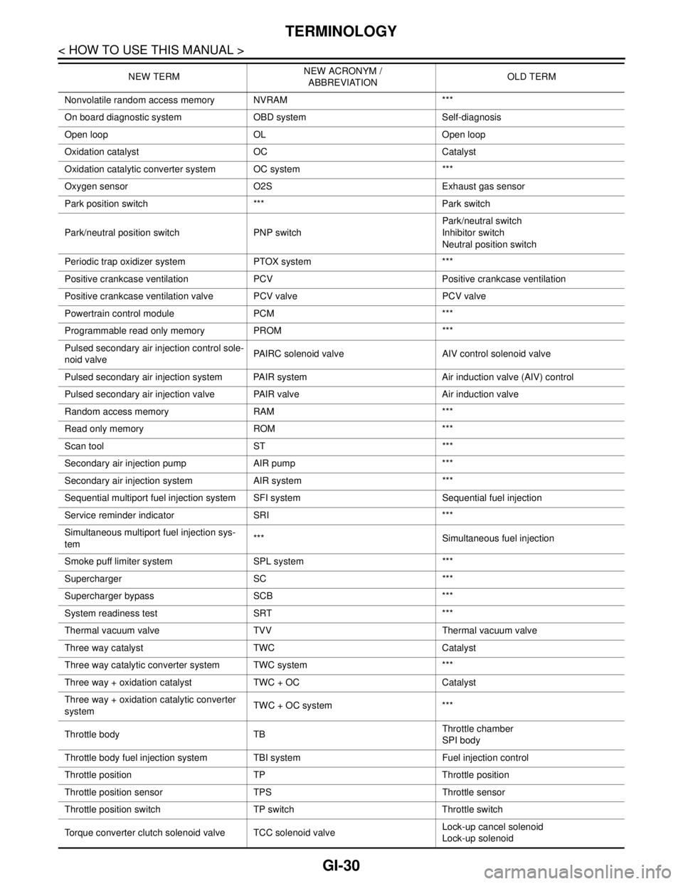
Nonvolatile random access memory NVRAM ***
On board diagnostic system OBD system Self-diagnosis
Open loop OL Open loop
Oxidation catalyst OC Catalyst
Oxidation catalytic converter system OC system ***
Oxygen sensor O2S Exhaust gas sensor
Park position switch *** Park switch
Park/neutral position switch PNP switchPark/neutral switch
Inhibitor switch
Neutral position switch
Periodic trap oxidizer system PTOX system ***
Positive crankcase ventilation PCV Positive crankcase ventilation
Positive crankcase ventilation valve PCV valve PCV valve
Powertrain control module PCM ***
Programmable read only memory PROM ***
Pulsed secondary air injection control sole-
noid valvePAIRC solenoid valve AIV control solenoid valve
Pulsed secondary air injection system PAIR system Air induction valve (AIV) control
Pulsed secondary air injection valve PAIR valve Air induction valve
Random access memory RAM ***
Read only memory ROM ***
Scan tool ST ***
Secondary air injection pump AIR pump ***
Secondary air injection system AIR system ***
Sequential multiport fuel injection system SFI system Sequential fuel injection
Service reminder indicator SRI ***
Simultaneous multiport fuel injection sys-
tem*** Simultaneous fuel injection
Smoke puff limiter system SPL system ***
Supercharger SC ***
Supercharger bypass SCB ***
System readiness test SRT ***
Thermal vacuum valve TVV Thermal vacuum valve
Three way catalyst TWC Catalyst
Three way catalytic converter system TWC system ***
Three way + oxidation catalyst TWC + OC Catalyst
Three way + oxidation catalytic converter
systemTWC + OC system ***
Throttle body TBThrottle chamber
SPI body
Throttle body fuel injection system TBI system Fuel injection control
Throttle position TP Throttle position
Throttle position sensor TPS Throttle sensor
Throttle position switch TP switch Throttle switch
Torque converter clutch solenoid valve TCC solenoid valveLock-up cancel solenoid
Lock-up solenoid NEW TERMNEW ACRONYM /
ABBREVIATIONOLD TERM
Page 3238 of 5883
GI-44
< PRECAUTION >
PRECAUTIONS
General Precaution
INFOID:0000000001606118
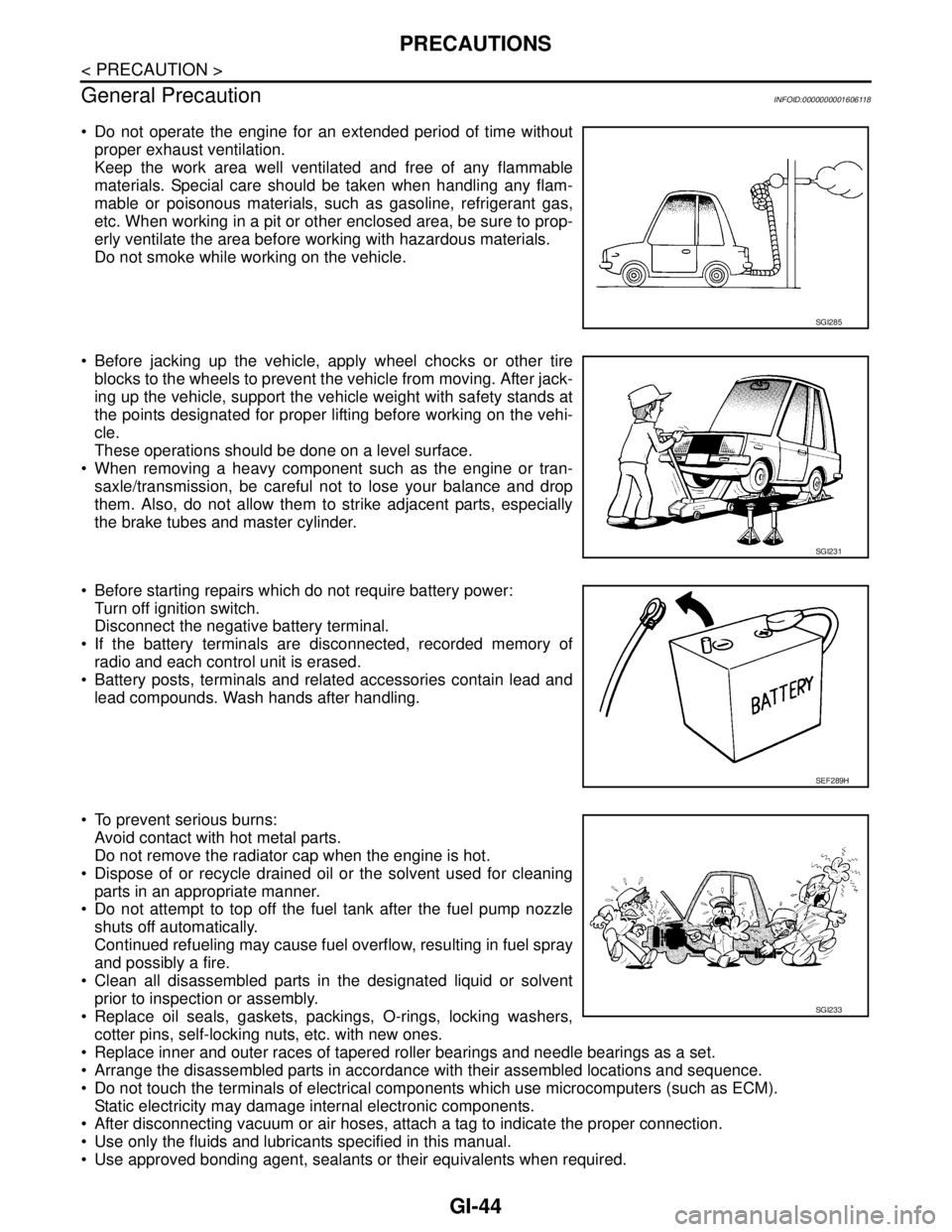
Do not operate the engine for an extended period of time without
proper exhaust ventilation.
Keep the work area well ventilated and free of any flammable
materials. Special care should be taken when handling any flam-
mable or poisonous materials, such as gasoline, refrigerant gas,
etc. When working in a pit or other enclosed area, be sure to prop-
erly ventilate the area before working with hazardous materials.
Do not smoke while working on the vehicle.
Before jacking up the vehicle, apply wheel chocks or other tire
blocks to the wheels to prevent the vehicle from moving. After jack-
ing up the vehicle, support the vehicle weight with safety stands at
the points designated for proper lifting before working on the vehi-
cle.
These operations should be done on a level surface.
When removing a heavy component such as the engine or tran-
saxle/transmission, be careful not to lose your balance and drop
them. Also, do not allow them to strike adjacent parts, especially
the brake tubes and master cylinder.
Before starting repairs which do not require battery power:
Turn off ignition switch.
Disconnect the negative battery terminal.
If the battery terminals are disconnected, recorded memory of
radio and each control unit is erased.
Battery posts, terminals and related accessories contain lead and
lead compounds. Wash hands after handling.
To prevent serious burns:
Avoid contact with hot metal parts.
Do not remove the radiator cap when the engine is hot.
Dispose of or recycle drained oil or the solvent used for cleaning
parts in an appropriate manner.
Do not attempt to top off the fuel tank after the fuel pump nozzle
shuts off automatically.
Continued refueling may cause fuel overflow, resulting in fuel spray
and possibly a fire.
Clean all disassembled parts in the designated liquid or solvent
prior to inspection or assembly.
Replace oil seals, gaskets, packings, O-rings, locking washers,
cotter pins, self-locking nuts, etc. with new ones.
Replace inner and outer races of tapered roller bearings and needle bearings as a set.
Arrange the disassembled parts in accordance with their assembled locations and sequence.
Do not touch the terminals of electrical components which use microcomputers (such as ECM).
Static electricity may damage internal electronic components.
After disconnecting vacuum or air hoses, attach a tag to indicate the proper connection.
Use only the fluids and lubricants specified in this manual.
Use approved bonding agent, sealants or their equivalents when required.
SGI285
SGI231
SEF289H
SGI233
Page 3283 of 5883
HA-1
VENTILATION, HEATER & AIR CONDITIONER
C
D
E
F
G
H
J
K
L
M
SECTION HA
A
B
HA
N
O
P
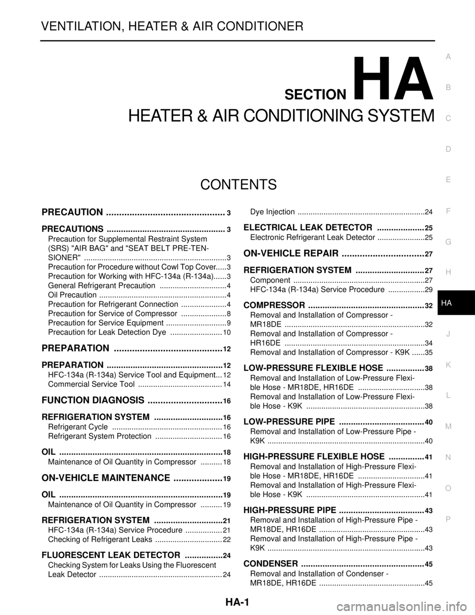
CONTENTS
HEATER & AIR CONDITIONING SYSTEM
PRECAUTION ...............................................3
PRECAUTIONS ...................................................3
Precaution for Supplemental Restraint System
(SRS) "AIR BAG" and "SEAT BELT PRE-TEN-
SIONER" ...................................................................
3
Precaution for Procedure without Cowl Top Cover ......3
Precaution for Working with HFC-134a (R-134a) ......3
General Refrigerant Precaution ................................4
Oil Precaution ............................................................4
Precaution for Refrigerant Connection ......................4
Precaution for Service of Compressor ......................8
Precaution for Service Equipment .............................9
Precaution for Leak Detection Dye .........................10
PREPARATION ...........................................12
PREPARATION ..................................................12
HFC-134a (R-134a) Service Tool and Equipment ....12
Commercial Service Tool ........................................14
FUNCTION DIAGNOSIS ..............................16
REFRIGERATION SYSTEM ..............................16
Refrigerant Cycle ....................................................16
Refrigerant System Protection ................................16
OIL ......................................................................18
Maintenance of Oil Quantity in Compressor ...........18
ON-VEHICLE MAINTENANCE ....................19
OIL ......................................................................19
Maintenance of Oil Quantity in Compressor ...........19
REFRIGERATION SYSTEM ..............................21
HFC-134a (R-134a) Service Procedure ..................21
Checking of Refrigerant Leaks ................................22
FLUORESCENT LEAK DETECTOR .................24
Checking System for Leaks Using the Fluorescent
Leak Detector ..........................................................
24
Dye Injection ............................................................24
ELECTRICAL LEAK DETECTOR ....................25
Electronic Refrigerant Leak Detector .......................25
ON-VEHICLE REPAIR .................................27
REFRIGERATION SYSTEM .............................27
Component ..............................................................27
HFC-134a (R-134a) Service Procedure ..................29
COMPRESSOR .................................................32
Removal and Installation of Compressor -
MR18DE ..................................................................
32
Removal and Installation of Compressor -
HR16DE ..................................................................
34
Removal and Installation of Compressor - K9K .......35
LOW-PRESSURE FLEXIBLE HOSE ................38
Removal and Installation of Low-Pressure Flexi-
ble Hose - MR18DE, HR16DE ................................
38
Removal and Installation of Low-Pressure Flexi-
ble Hose - K9K ........................................................
38
LOW-PRESSURE PIPE ....................................40
Removal and Installation of Low-Pressure Pipe -
K9K ..........................................................................
40
HIGH-PRESSURE FLEXIBLE HOSE ...............41
Removal and Installation of High-Pressure Flexi-
ble Hose - MR18DE, HR16DE ................................
41
Removal and Installation of High-Pressure Flexi-
ble Hose - K9K ........................................................
41
HIGH-PRESSURE PIPE ....................................43
Removal and Installation of High-Pressure Pipe -
MR18DE, HR16DE ..................................................
43
Removal and Installation of High-Pressure Pipe -
K9K ..........................................................................
43
CONDENSER ....................................................45
Removal and Installation of Condenser -
MR18DE, HR16DE ..................................................
45
Page 3308 of 5883
HA-26
< ON-VEHICLE MAINTENANCE >
ELECTRICAL LEAK DETECTOR
2. Connect a suitable A/C manifold gauge set to the A/C service ports.
3. Check if the A/C refrigerant pressure is at least 345 kPa (3.45 bar, 3.52 kg/cm
2, 50 psi) above 16°C. If less
than specification, recover/evacuate and recharge the system with the specified amount of refrigerant.
NOTE:
At temperatures below 16°C, leaks may not be detected since the system may not reach 345 kPa (3.45
bar, 3.52 kg/cm
2, 50 psi).
4. Perform the leak test from the high-pressure side (compressor discharge a to evaporator inlet f) to the
low-pressure side (evaporator drain hose g to shaft seal k). Refer to HA-27, "
Component". Perform a leak
check for the following areas carefully. Clean the component to be checked and move the leak detected
probe completely around the connection/component.
Compressor
Check the fitting of high- and low-pressure flexible hoses, relief valve and shaft seal.
Condenser
Check the fitting of high-pressure flexible hose and pipe, refrigerant pressure sensor.
Liquid tank
Check the refrigerant connection.
Service valves
Check all around the service valves. Ensure service valve caps are secured on the service valves (to
prevent leaks).
NOTE:
After removing A/C manifold gauge set from service valves, wipe any residue from valves to prevent any
false readings by leak detector.
Cooling unit (Evaporator)
With engine OFF, turn blower fan on “High” for at least 15 seconds to dissipate any refrigerant trace in
the cooling unit. Wait a minimum of 10 minutes accumulation time (refer to the manufacturer’s recom-
mended procedure for actual wait time) before inserting the leak detector probe into the drain hose.
Keep the probe inserted for at least 10 seconds. Use caution not to contaminate the probe tip with water
or dirt that may be in the drain hose.
5. If a leak detector detects a leak, verify at least once by blowing compressed air into area of suspected
leak, then repeat check as outlined above.
6. Do not stop when one leak is found. Continue to check for additional leaks at all system components.
If no leaks are found, perform steps 7-10.
7. Start engine.
8. Set the heater A/C control as follows;
a. A/C switch: ON
b. Mode control dial position: VENT (Ventilation)
c. Intake door lever position: Recirculation
d. Max. cold temperature
e. Fan speed: High
9. Run engine at 1,500 rpm for at least 2 minutes.
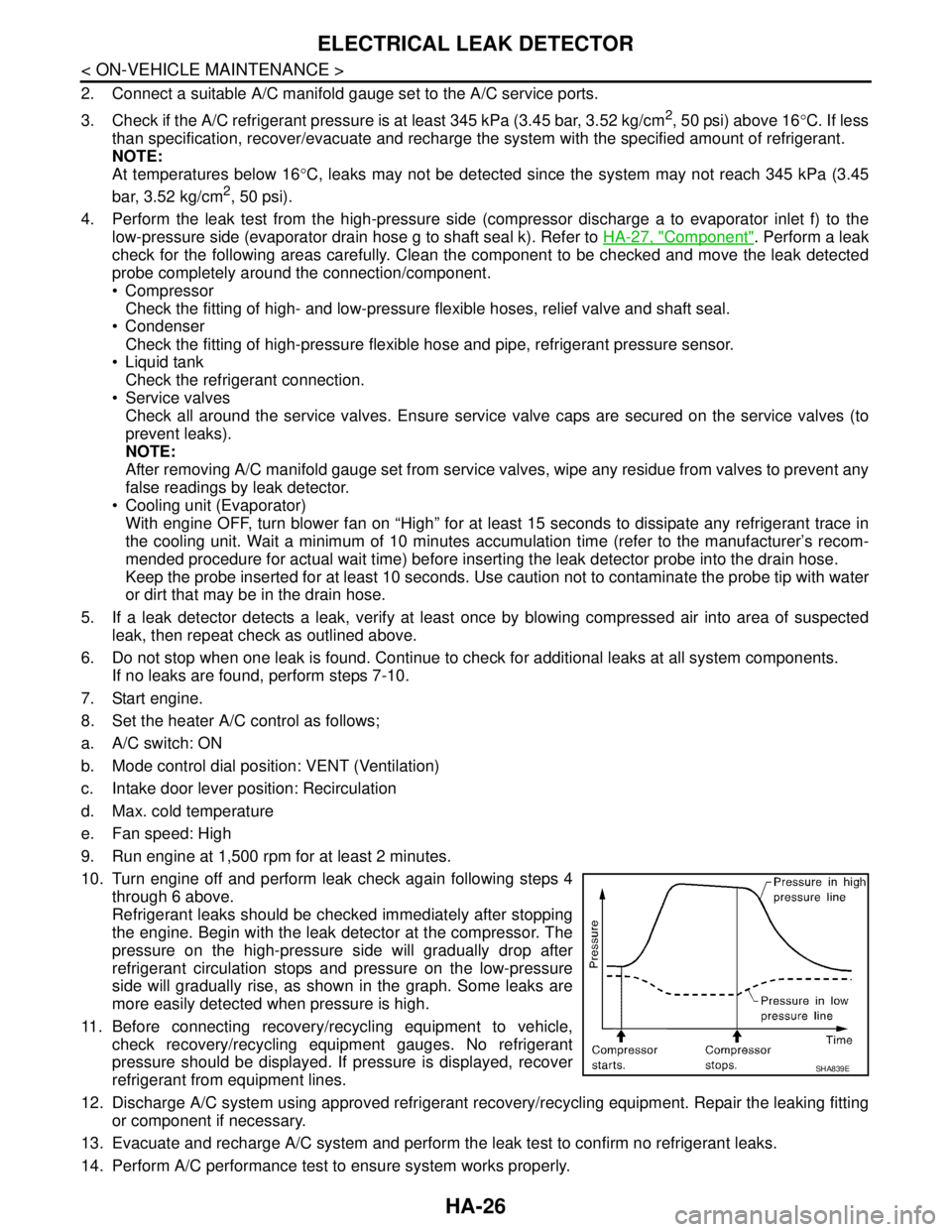
10. Turn engine off and perform leak check again following steps 4
through 6 above.
Refrigerant leaks should be checked immediately after stopping
the engine. Begin with the leak detector at the compressor. The
pressure on the high-pressure side will gradually drop after
refrigerant circulation stops and pressure on the low-pressure
side will gradually rise, as shown in the graph. Some leaks are
more easily detected when pressure is high.
11. Before connecting recovery/recycling equipment to vehicle,
check recovery/recycling equipment gauges. No refrigerant
pressure should be displayed. If pressure is displayed, recover
refrigerant from equipment lines.
12. Discharge A/C system using approved refrigerant recovery/recycling equipment. Repair the leaking fitting
or component if necessary.
13. Evacuate and recharge A/C system and perform the leak test to confirm no refrigerant leaks.
14. Perform A/C performance test to ensure system works properly.
SHA839E
Page 3334 of 5883
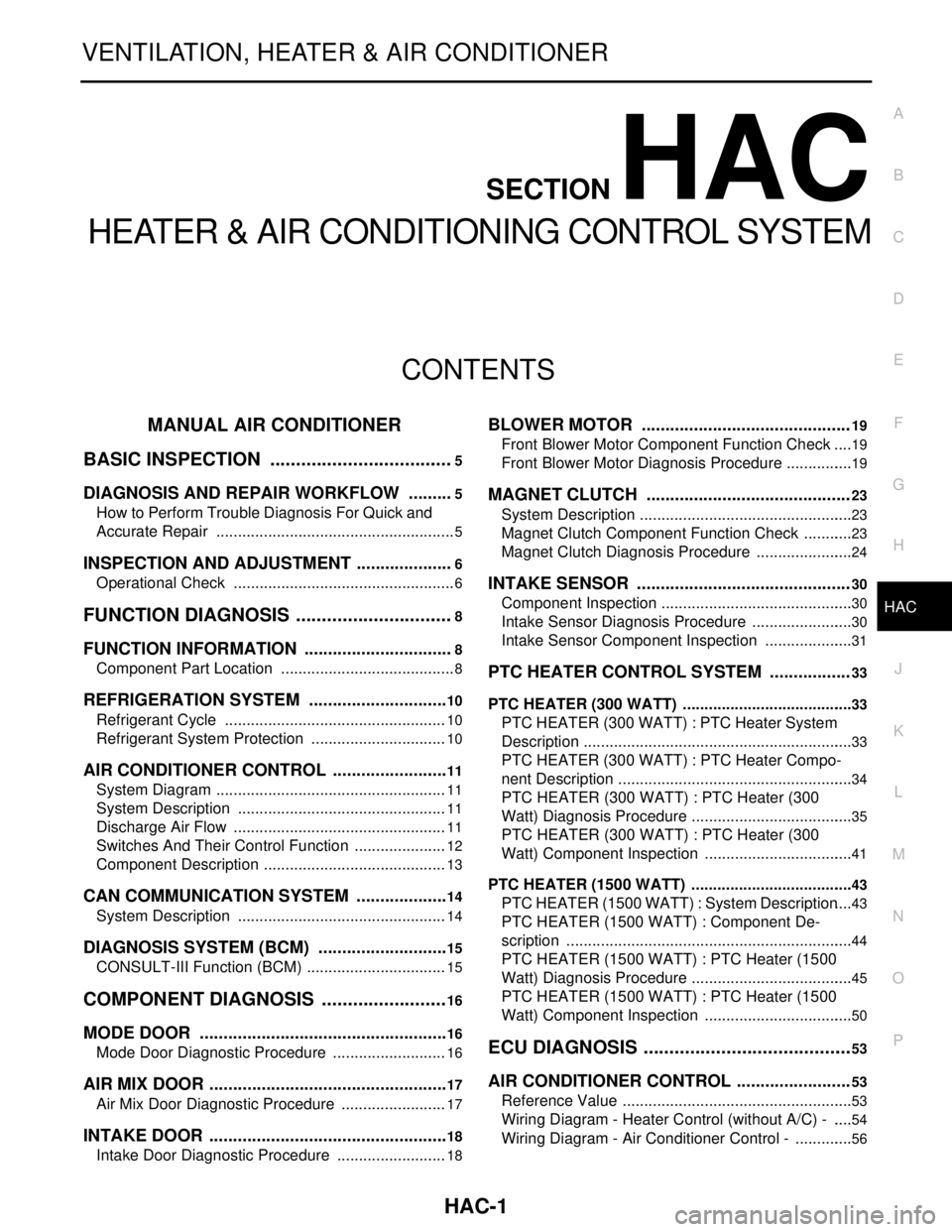
HAC-1
VENTILATION, HEATER & AIR CONDITIONER
C
D
E
F
G
H
J
K
L
M
SECTION HAC
A
B
HAC
N
O
P
CONTENTS
HEATER & AIR CONDITIONING CONTROL SYSTEM
MANUAL AIR CONDITIONER
BASIC INSPECTION ....................................
5
DIAGNOSIS AND REPAIR WORKFLOW ..........5
How to Perform Trouble Diagnosis For Quick and
Accurate Repair ........................................................
5
INSPECTION AND ADJUSTMENT .....................6
Operational Check ....................................................6
FUNCTION DIAGNOSIS ...............................8
FUNCTION INFORMATION ................................8
Component Part Location .........................................8
REFRIGERATION SYSTEM ..............................10
Refrigerant Cycle ....................................................10
Refrigerant System Protection ................................10
AIR CONDITIONER CONTROL .........................11
System Diagram ......................................................11
System Description .................................................11
Discharge Air Flow ..................................................11
Switches And Their Control Function ......................12
Component Description ...........................................13
CAN COMMUNICATION SYSTEM ....................14
System Description .................................................14
DIAGNOSIS SYSTEM (BCM) ............................15
CONSULT-III Function (BCM) .................................15
COMPONENT DIAGNOSIS .........................16
MODE DOOR .....................................................16
Mode Door Diagnostic Procedure ...........................16
AIR MIX DOOR ...................................................17
Air Mix Door Diagnostic Procedure .........................17
INTAKE DOOR ...................................................18
Intake Door Diagnostic Procedure ..........................18
BLOWER MOTOR ............................................19
Front Blower Motor Component Function Check ....19
Front Blower Motor Diagnosis Procedure ................19
MAGNET CLUTCH ...........................................23
System Description ..................................................23
Magnet Clutch Component Function Check ............23
Magnet Clutch Diagnosis Procedure .......................24
INTAKE SENSOR .............................................30
Component Inspection .............................................30
Intake Sensor Diagnosis Procedure ........................30
Intake Sensor Component Inspection .....................31
PTC HEATER CONTROL SYSTEM .................33
PTC HEATER (300 WATT) ........................................33
PTC HEATER (300 WATT) : PTC Heater System
Description ...............................................................
33
PTC HEATER (300 WATT) : PTC Heater Compo-
nent Description .......................................................
34
PTC HEATER (300 WATT) : PTC Heater (300
Watt) Diagnosis Procedure ......................................
35
PTC HEATER (300 WATT) : PTC Heater (300
Watt) Component Inspection ...................................
41
PTC HEATER (1500 WATT) ......................................43
PTC HEATER (1500 WATT) : System Description ....43
PTC HEATER (1500 WATT) : Component De-
scription ...................................................................
44
PTC HEATER (1500 WATT) : PTC Heater (1500
Watt) Diagnosis Procedure ......................................
45
PTC HEATER (1500 WATT) : PTC Heater (1500
Watt) Component Inspection ...................................
50
ECU DIAGNOSIS .........................................53
AIR CONDITIONER CONTROL ........................53
Reference Value ......................................................53
Wiring Diagram - Heater Control (without A/C) - .....54
Wiring Diagram - Air Conditioner Control - ..............56
Page 3409 of 5883

HAC-76
< SYMPTOM DIAGNOSIS >[MANUAL AIR CONDITIONER]
INSUFFICIENT COOLING
Testing must be performed as follows:
Test Reading
Recirculating-to-discharge Air Temperature Table
Ambient Air Temperature-to-operating Pressure Table
*1: With blower control dial in the "1" position
*2: With blower control dial in the "4" position.
Test ReadingINFOID:0000000001547076
Recirculating-to-discharge Air Temperature Table
Vehicle condition Indoors or in the shade (in a well-ventilated place)
Doors Closed
Door window Open
Hood Open
TEMP. Max. COLD
Mode control dial
(Ventilation) set
Intake door lever
(Recirculation) set
Blower speedMax. speed set
Engine speed Idle speed
Operate the air conditioning system for 10 minutes before taking measurements.
Inside air (Recirculating air) at blower assembly inlet
Discharge air temperature at center ventilator
°C (°F) Relative humidity
%Air temperature
°C (°F)
50 - 6020 (68) 7.2 - 9.1 (45 - 48)
25 (77) 11.4 - 13.8 (53 - 57)
30 (86) 15.5 - 18.4 (60 - 65)
35 (95) 20.3 - 23.7 (69 - 75)
60 - 7020 (68) 9.1 - 10.9 (48 - 52)
25 (77) 13.8 - 16.2 (57 - 61)
30 (86) 18.4 - 21.3 (65 - 70)
35 (95) 23.7 - 27.1 (75 - 81)
Ambient air
High-pressure (Discharge side)
kPa (bar, kg/cm
2 , psi)Low-pressure (Suction side)
kPa (bar, kg/cm2 , psi) Relative humidity
%Air temperature
°C (°F)
50 - 7020 (68)843 - 1,036 *1
(11.08 - 13.63, 8.6 - 10.6, 122 - 150)159.0 - 194.0
(1.59 - 1.94, 1.62 - 1.98, 23.1 - 28.1)
25 (77)1,094 - 1,338 *1
(10.94 - 13.38, 11.2 - 13.6, 159 - 194)196.3 - 240.0
(1.96 - 2.40, 2.00 - 2.45, 28.5 - 34.8)
30 (86)1,298 - 1,590 *1
(12.98 - 15.90, 13.2 - 16.2, 188 - 231)248.0 - 302.7
(2.48 - 3.03, 2.53 - 3.09, 36.0 - 43.9)
35 (95)1,383 - 1,688 *2
(13.83 - 16.88, 14.1 - 17.2, 201 - 245)308.8 - 377.4
(3.09 - 3.77, 3.15 - 3.85, 44.8 - 54.7)
40 (104)1,628 - 1,988 *2
(16.28 - 19.88, 16.6 - 20.3, 236 - 288)377.4 - 461.2
(3.77 - 4.61, 3.85 - 4.70, 54.7 - 66.8)
Page 3522 of 5883

INSUFFICIENT COOLING
HAC-189
< SYMPTOM DIAGNOSIS >[AUTO AIR CONDITIONER (W/O NAVI)]
C
D
E
F
G
H
J
K
L
MA
B
HAC
N
O
P
Testing must be performed as follows:
Test ReadingINFOID:0000000001547455
TEST READING
Recirculating-to-discharge Air Temperature Table
Ambient Air Temperature-to-operating Pressure Table
*1: In the motor fan low-speed control
*2: In the motor fan high-speed control
Trouble Diagnoses for Unusual PressureINFOID:0000000001547456
TROUBLE DIAGNOSIS FOR UNUSUAL PRESSURE
Vehicle condition Indoors or in the shade (in a well-ventilated place)
Doors Closed
Door window Open
Hood Open
TEMP. Max. COLD
Mode switch
(Ventilation) set
Recirculation (REC) switch
(Recirculation) set
Fan (blower) speedMax. speed set
Engine speed Idle speed
Operate the air conditioning system for 10 minutes before taking measurements.
Inside air (Recirculating air) at blower assembly inlet
Discharge air temperature at center ventilator
°C (°F) Relative humidity
%Air temperature
°C (°F)
50 - 6020 (68) 7.2 - 9.1 (45 - 48)
25 (77) 11.4 - 13.8 (53 - 57)
30 (86) 15.5 - 18.4 (60 - 65)
35 (95) 20.3 - 23.7 (69 - 75)
60 - 7020 (68) 9.1 - 10.9 (48 - 52)
25 (77) 13.8 - 16.2 (57 - 61)
30 (86) 18.4 - 21.3 (65 - 70)
35 (95) 23.7 - 27.1 (75 - 81)
Ambient air
High-pressure (Discharge side)
kPa (bar, kg/cm
2, psi)Low-pressure (Suction side)
kPa (bar, kg/cm2, psi) Relative humidity
%Air temperature
°C (°F)
50 - 7020 (68)843 - 1,036 *1
(11.08 - 13.63, 8.6 - 10.6, 122 - 150)159.0 - 194.0
(1.59 - 1.94, 1.62 - 1.98, 23.1 - 28.1)
25 (77)1,094 - 1,338 *1
(10.94 - 13.38, 11.2 - 13.6, 159 - 194)196.3 - 240.0
(1.96 - 2.40, 2.00 - 2.45, 28.5 - 34.8)
30 (86)1,298 - 1,590 *1
(12.98 - 15.90, 13.2 - 16.2, 188 - 231)248.0 - 302.7
(2.48 - 3.03, 2.53 - 3.09, 36.0 - 43.9)
35 (95)1,383 - 1,688 *2
(13.83 - 16.88, 14.1 - 17.2, 201 - 245)308.8 - 377.4
(3.09 - 3.77, 3.15 - 3.85, 44.8 - 54.7)
40 (104)1,628 - 1,988 *2
(16.28 - 19.88, 16.6 - 20.3, 236 - 288)377.4 - 461.2
(3.77 - 4.61, 3.85 - 4.70, 54.7 - 66.8)