2007 NISSAN TIIDA Radio
[x] Cancel search: RadioPage 412 of 5883
![NISSAN TIIDA 2007 Service Repair Manual PRECAUTIONS
BRC-179
< PRECAUTION >[ESP/TCS/ABS]
C
D
E
G
H
I
J
K
L
MA
B
BRC
N
O
P
PRECAUTION
PRECAUTIONS
Precaution for Supplemental Restraint System (SRS) "AIR BAG" and "SEAT BELT
PRE-TENSIONER"
INFO NISSAN TIIDA 2007 Service Repair Manual PRECAUTIONS
BRC-179
< PRECAUTION >[ESP/TCS/ABS]
C
D
E
G
H
I
J
K
L
MA
B
BRC
N
O
P
PRECAUTION
PRECAUTIONS
Precaution for Supplemental Restraint System (SRS) "AIR BAG" and "SEAT BELT
PRE-TENSIONER"
INFO](/manual-img/5/57395/w960_57395-411.png)
PRECAUTIONS
BRC-179
< PRECAUTION >[ESP/TCS/ABS]
C
D
E
G
H
I
J
K
L
MA
B
BRC
N
O
P
PRECAUTION
PRECAUTIONS
Precaution for Supplemental Restraint System (SRS) "AIR BAG" and "SEAT BELT
PRE-TENSIONER"
INFOID:0000000001691411
The Supplemental Restraint System such as “AIR BAG” and “SEAT BELT PRE-TENSIONER”, used along
with a front seat belt, helps to reduce the risk or severity of injury to the driver and front passenger for certain
types of collision. Information necessary to service the system safely is included in the SRS and SB section of
this Service Manual.
WARNING:
To avoid rendering the SRS inoperative, which could increase the risk of personal injury or death in
the event of a collision which would result in air bag inflation, all maintenance must be performed by
an authorized NISSAN/INFINITI dealer.
Improper maintenance, including incorrect removal and installation of the SRS, can lead to personal
injury caused by unintentional activation of the system. For removal of Spiral Cable and Air Bag
Module, see the SRS section.
Do not use electrical test equipment on any circuit related to the SRS unless instructed to in this
Service Manual. SRS wiring harnesses can be identified by yellow and/or orange harnesses or har-
ness connectors.
Precaution for Brake SystemINFOID:0000000001691412
Recommended fluid is Genuine NISSAN Fluid, DOT 3 or DOT 4 (US FMVSS No. 116).
Do not reuse drained brake fluid.
Be careful not to splash brake fluid on painted areas such as body. If brake fluid is splashed, wipe it off and
flush area with water immediately.
Do not use mineral oils such as gasoline or kerosene to clean. They will ruin rubber parts and cause
improper operation.
Using a flare nut torque wrench, securely tighten brake tube flare
nuts.
Brake system is an important safety part. If a brake fluid leak is
detected, always disassemble the affected part. If a malfunction is
detected, replace part with a new one.
Before working, turn ignition switch OFF and disconnect electrical
connectors of ABS actuator and electric unit (control unit) or bat-
tery negative terminals.
When installing brake piping, be sure to check torque.
After removing/installing any hydraulic parts of the brake or ESP
system (such as actuator and piping parts, etc), bleed air from the
system.
Precaution for Brake ControlINFOID:0000000001691413
During ESP/TCS/ABS operation, brake pedal lightly vibrates and a mechanical noise may be heard. This is
normal.
When starting engine, or just after starting vehicle, brake pedal may vibrate or motor operating noise may be
heard from engine room. This is a normal status of operation check.
Stopping distance may be longer than that of vehicles without ABS when vehicle drives on rough, gravel, or
snow-covered (fresh, deep snow) roads.
When an error is indicated by ABS or another warning lamp, collect all necessary information from the cus-
tomer (what symptoms are present under what conditions) and check for simple causes before starting diag-
nostic servicing. Besides the electrical system inspection, check booster operation, brake fluid level, and
fluid leaks.
If tire size and type are used in an improper combination, or brake pads are not Genuine NISSAN parts,
stopping distance or steering stability may deteriorate.
If there is a radio, antenna, or antenna lead-in wire (including wiring) near control module, ESP/TCS/ABS
function may have a malfunction or error.
If aftermarket parts (car stereo, CD player, etc.) have been installed, check for incidents such as harness
pinches, open circuits, and improper wiring.
SBR820BA
Page 1723 of 5883
![NISSAN TIIDA 2007 Service Repair Manual EC-374
< PRECAUTION >[HR16DE (WITH EURO-OBD)]
PRECAUTIONS
When measuring ECM signals with a circuit tester, never allow
the two tester probes to contact.
Accidental contact of probes will cause a sho NISSAN TIIDA 2007 Service Repair Manual EC-374
< PRECAUTION >[HR16DE (WITH EURO-OBD)]
PRECAUTIONS
When measuring ECM signals with a circuit tester, never allow
the two tester probes to contact.
Accidental contact of probes will cause a sho](/manual-img/5/57395/w960_57395-1722.png)
EC-374
< PRECAUTION >[HR16DE (WITH EURO-OBD)]
PRECAUTIONS
When measuring ECM signals with a circuit tester, never allow
the two tester probes to contact.
Accidental contact of probes will cause a short circuit and
damage the ECM power transistor.
Do not use ECM ground terminals when measuring input/out-
put voltage. Doing so may result in damage to the ECM’s tran-
sistor. Use a ground other than ECM terminals, such as the
ground.
Do not operate fuel pump when there is no fuel in lines.
Tighten fuel hose clamps to the specified torque.
Do not depress accelerator pedal when starting.
Immediately after starting, do not rev up engine unnecessar-
ily.
Do not rev up engine just prior to shutdown.
When installing C.B. ham radio or a mobile phone, be sure to
observe the following as it may adversely affect electronic
control systems depending on installation location.
-Keep the antenna as far as possible from the electronic con-
trol units.
-Keep the antenna feeder line more than 20 cm (8 in) away
from the harness of electronic controls.
Do not let them run parallel for a long distance.
-Adjust the antenna and feeder line so that the standing-wave
ratio can be kept smaller.
-Be sure to ground the radio to vehicle body.
SEF348N
SEF709Y
SEF708Y
Page 2027 of 5883
![NISSAN TIIDA 2007 Service Repair Manual EC-678
< PRECAUTION >[HR16DE (WITHOUT EURO-OBD)]
PRECAUTIONS
When measuring ECM signals with a circuit tester, never allow
the two tester probes to contact.
Accidental contact of probes will cause a NISSAN TIIDA 2007 Service Repair Manual EC-678
< PRECAUTION >[HR16DE (WITHOUT EURO-OBD)]
PRECAUTIONS
When measuring ECM signals with a circuit tester, never allow
the two tester probes to contact.
Accidental contact of probes will cause a](/manual-img/5/57395/w960_57395-2026.png)
EC-678
< PRECAUTION >[HR16DE (WITHOUT EURO-OBD)]
PRECAUTIONS
When measuring ECM signals with a circuit tester, never allow
the two tester probes to contact.
Accidental contact of probes will cause a short circuit and
damage the ECM power transistor.
Do not use ECM ground terminals when measuring input/out-
put voltage. Doing so may result in damage to the ECM’s tran-
sistor. Use a ground other than ECM terminals, such as the
ground.
Do not operate fuel pump when there is no fuel in lines.
Tighten fuel hose clamps to the specified torque.
Do not depress accelerator pedal when starting.
Immediately after starting, do not rev up engine unnecessar-
ily.
Do not rev up engine just prior to shutdown.
When installing C.B. ham radio or a mobile phone, be sure to
observe the following as it may adversely affect electronic
control systems depending on installation location.
-Keep the antenna as far as possible from the electronic con-
trol units.
-Keep the antenna feeder line more than 20 cm (8 in) away
from the harness of electronic controls.
Do not let them run parallel for a long distance.
-Adjust the antenna and feeder line so that the standing-wave
ratio can be kept smaller.
-Be sure to ground the radio to vehicle body.
SEF348N
SEF709Y
SEF708Y
Page 2381 of 5883
![NISSAN TIIDA 2007 Service Repair Manual EC-1032
< PRECAUTION >[MR18DE]
PRECAUTIONS
When measuring ECM signals with a circuit tester, never allow
the two tester probes to contact.
Accidental contact of probes will cause a short circuit and
NISSAN TIIDA 2007 Service Repair Manual EC-1032
< PRECAUTION >[MR18DE]
PRECAUTIONS
When measuring ECM signals with a circuit tester, never allow
the two tester probes to contact.
Accidental contact of probes will cause a short circuit and](/manual-img/5/57395/w960_57395-2380.png)
EC-1032
< PRECAUTION >[MR18DE]
PRECAUTIONS
When measuring ECM signals with a circuit tester, never allow
the two tester probes to contact.
Accidental contact of probes will cause a short circuit and
damage the ECM power transistor.
Do not use ECM ground terminals when measuring input/out-
put voltage. Doing so may result in damage to the ECM’s tran-
sistor. Use a ground other than ECM terminals, such as the
ground.
Do not operate fuel pump when there is no fuel in lines.
Tighten fuel hose clamps to the specified torque.
Do not depress accelerator pedal when starting.
Immediately after starting, do not rev up engine unnecessar-
ily.
Do not rev up engine just prior to shutdown.
When installing C.B. ham radio or a mobile phone, be sure to
observe the following as it may adversely affect electronic
control systems depending on installation location.
-Keep the antenna as far as possible from the electronic con-
trol units.
-Keep the antenna feeder line more than 20 cm (8 in) away
from the harness of electronic controls.
Do not let them run parallel for a long distance.
-Adjust the antenna and feeder line so that the standing-wave
ratio can be kept smaller.
-Be sure to ground the radio to vehicle body.
SEF348N
SEF709Y
SEF708Y
Page 2644 of 5883
![NISSAN TIIDA 2007 Service Repair Manual PRECAUTIONS
EC-1295
< PRECAUTION >[K9K]
C
D
E
F
G
H
I
J
K
L
MA
EC
N
P O
When measuring ECM signals with a circuit tester, never allow
the two tester probes to contact.
Accidental contact of probes wi NISSAN TIIDA 2007 Service Repair Manual PRECAUTIONS
EC-1295
< PRECAUTION >[K9K]
C
D
E
F
G
H
I
J
K
L
MA
EC
N
P O
When measuring ECM signals with a circuit tester, never allow
the two tester probes to contact.
Accidental contact of probes wi](/manual-img/5/57395/w960_57395-2643.png)
PRECAUTIONS
EC-1295
< PRECAUTION >[K9K]
C
D
E
F
G
H
I
J
K
L
MA
EC
N
P O
When measuring ECM signals with a circuit tester, never allow
the two tester probes to contact.
Accidental contact of probes will cause a short circuit and
damage the ECM power transistor.
Do not use ECM ground terminals when measuring input/out-
put voltage. Doing so may result in damage to the ECM's tran-
sistor. Use a ground other than ECM terminals, such as the
ground.
Do not disassemble fuel pump.
If NG, take proper action.
Do not disassemble fuel injector.
If NG, replace fuel injector.
Do not depress accelerator pedal when staring.
Immediately after staring, do not rev up engine unnecessarily.
Do not rev up engine just prior to shutdown.
When installing C.B. ham radio or a mobile phone, be sure to
observe the following as it may adversely affect electronic
control systems depending on installation location.
-Keep the antenna as far as possible from the electronic con-
trol units.
-Keep the antenna feeder line more than 20 cm (8 in) away
from the harness of electronic controls.
Do not let them run parallel for a long distance.
-Adjust the antenna and feeder line so that the standingwave
radio can be kept smaller.
-Be sure to ground the radio to vehicle body.
SEF348N
SEF709Y
SEF708Y
Page 3238 of 5883

GI-44
< PRECAUTION >
PRECAUTIONS
General Precaution
INFOID:0000000001606118
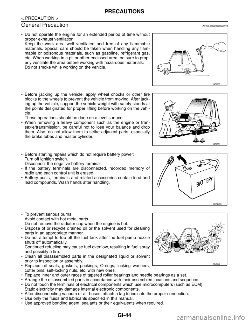
Do not operate the engine for an extended period of time without
proper exhaust ventilation.
Keep the work area well ventilated and free of any flammable
materials. Special care should be taken when handling any flam-
mable or poisonous materials, such as gasoline, refrigerant gas,
etc. When working in a pit or other enclosed area, be sure to prop-
erly ventilate the area before working with hazardous materials.
Do not smoke while working on the vehicle.
Before jacking up the vehicle, apply wheel chocks or other tire
blocks to the wheels to prevent the vehicle from moving. After jack-
ing up the vehicle, support the vehicle weight with safety stands at
the points designated for proper lifting before working on the vehi-
cle.
These operations should be done on a level surface.
When removing a heavy component such as the engine or tran-
saxle/transmission, be careful not to lose your balance and drop
them. Also, do not allow them to strike adjacent parts, especially
the brake tubes and master cylinder.
Before starting repairs which do not require battery power:
Turn off ignition switch.
Disconnect the negative battery terminal.
If the battery terminals are disconnected, recorded memory of
radio and each control unit is erased.
Battery posts, terminals and related accessories contain lead and
lead compounds. Wash hands after handling.
To prevent serious burns:
Avoid contact with hot metal parts.
Do not remove the radiator cap when the engine is hot.
Dispose of or recycle drained oil or the solvent used for cleaning
parts in an appropriate manner.
Do not attempt to top off the fuel tank after the fuel pump nozzle
shuts off automatically.
Continued refueling may cause fuel overflow, resulting in fuel spray
and possibly a fire.
Clean all disassembled parts in the designated liquid or solvent
prior to inspection or assembly.
Replace oil seals, gaskets, packings, O-rings, locking washers,
cotter pins, self-locking nuts, etc. with new ones.
Replace inner and outer races of tapered roller bearings and needle bearings as a set.
Arrange the disassembled parts in accordance with their assembled locations and sequence.
Do not touch the terminals of electrical components which use microcomputers (such as ECM).
Static electricity may damage internal electronic components.
After disconnecting vacuum or air hoses, attach a tag to indicate the proper connection.
Use only the fluids and lubricants specified in this manual.
Use approved bonding agent, sealants or their equivalents when required.
SGI285
SGI231
SEF289H
SGI233
Page 3245 of 5883

SERVICE INFORMATION FOR ELECTRICAL INCIDENT
GI-51
< BASIC INSPECTION >
C
D
E
F
G
H
I
J
K
L
MB
GI
N
O
PBASIC INSPECTION
SERVICE INFORMATION FOR ELECTRICAL INCIDENT
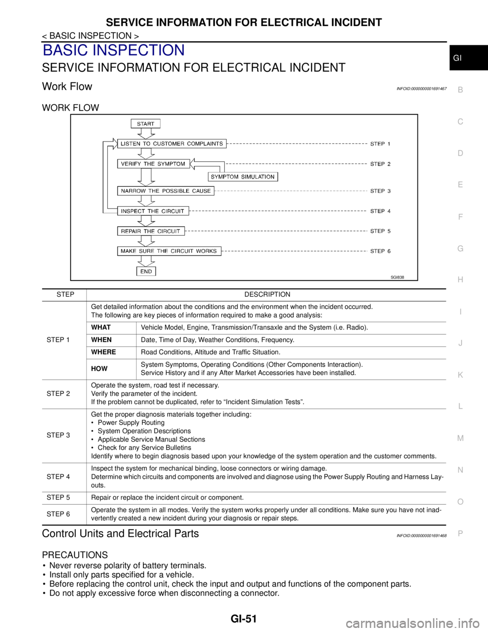
Work FlowINFOID:0000000001691467
WORK FLOW
Control Units and Electrical PartsINFOID:0000000001691468
PRECAUTIONS
Never reverse polarity of battery terminals.
Install only parts specified for a vehicle.
Before replacing the control unit, check the input and output and functions of the component parts.
Do not apply excessive force when disconnecting a connector.
SGI838
STEP DESCRIPTION
STEP 1Get detailed information about the conditions and the environment when the incident occurred.
The following are key pieces of information required to make a good analysis:
WHATVehicle Model, Engine, Transmission/Transaxle and the System (i.e. Radio).
WHENDate, Time of Day, Weather Conditions, Frequency.
WHERERoad Conditions, Altitude and Traffic Situation.
HOWSystem Symptoms, Operating Conditions (Other Components Interaction).
Service History and if any After Market Accessories have been installed.
STEP 2Operate the system, road test if necessary.
Verify the parameter of the incident.
If the problem cannot be duplicated, refer to “Incident Simulation Tests”.
STEP 3Get the proper diagnosis materials together including:
Power Supply Routing
System Operation Descriptions
Applicable Service Manual Sections
Check for any Service Bulletins
Identify where to begin diagnosis based upon your knowledge of the system operation and the customer comments.
STEP 4Inspect the system for mechanical binding, loose connectors or wiring damage.
Determine which circuits and components are involved and diagnose using the Power Supply Routing and Harness Lay-
outs.
STEP 5 Repair or replace the incident circuit or component.
STEP 6Operate the system in all modes. Verify the system works properly under all conditions. Make sure you have not inad-
vertently created a new incident during your diagnosis or repair steps.
Page 3251 of 5883

SERVICE INFORMATION FOR ELECTRICAL INCIDENT
GI-57
< BASIC INSPECTION >
C
D
E
F
G
H
I
J
K
L
MB
GI
N
O
P
An unclamped or loose harness can cause wiring to be pinched by seat components (such as slide guides)
during vehicle vibration. If the wiring runs under seating areas, inspect wire routing for possible damage or
pinching.
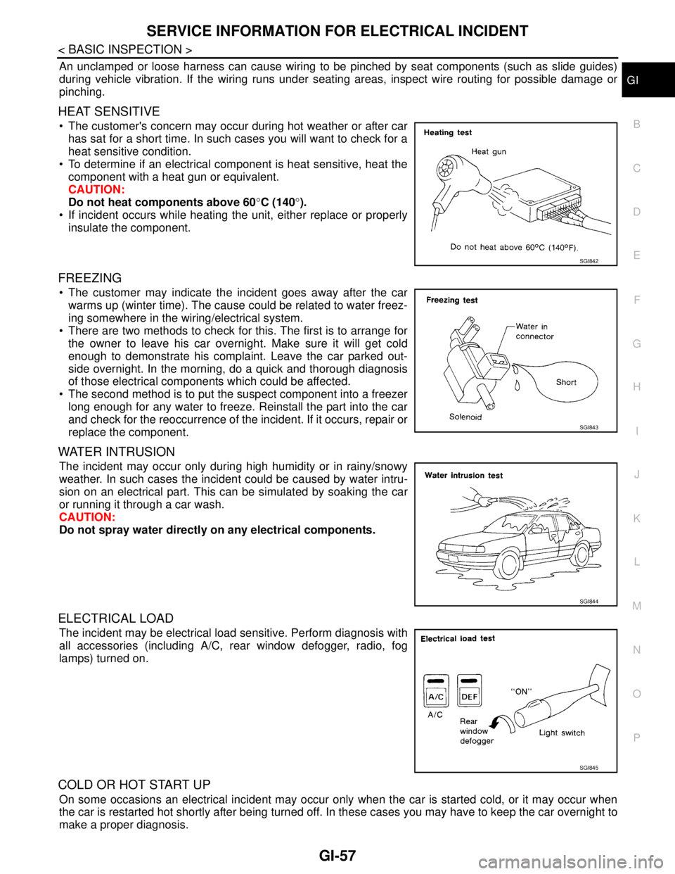
HEAT SENSITIVE
The customer's concern may occur during hot weather or after car
has sat for a short time. In such cases you will want to check for a
heat sensitive condition.
To determine if an electrical component is heat sensitive, heat the
component with a heat gun or equivalent.
CAUTION:
Do not heat components above 60°C (140°).
If incident occurs while heating the unit, either replace or properly
insulate the component.
FREEZING
The customer may indicate the incident goes away after the car
warms up (winter time). The cause could be related to water freez-
ing somewhere in the wiring/electrical system.
There are two methods to check for this. The first is to arrange for
the owner to leave his car overnight. Make sure it will get cold
enough to demonstrate his complaint. Leave the car parked out-
side overnight. In the morning, do a quick and thorough diagnosis
of those electrical components which could be affected.
The second method is to put the suspect component into a freezer
long enough for any water to freeze. Reinstall the part into the car
and check for the reoccurrence of the incident. If it occurs, repair or
replace the component.
WATER INTRUSION
The incident may occur only during high humidity or in rainy/snowy
weather. In such cases the incident could be caused by water intru-
sion on an electrical part. This can be simulated by soaking the car
or running it through a car wash.
CAUTION:
Do not spray water directly on any electrical components.
ELECTRICAL LOAD
The incident may be electrical load sensitive. Perform diagnosis with
all accessories (including A/C, rear window defogger, radio, fog
lamps) turned on.
COLD OR HOT START UP
On some occasions an electrical incident may occur only when the car is started cold, or it may occur when
the car is restarted hot shortly after being turned off. In these cases you may have to keep the car overnight to
make a proper diagnosis.
SGI842
SGI843
SGI844
SGI845