2007 NISSAN TIIDA window
[x] Cancel search: windowPage 4488 of 5883
POWER WINDOW MOTOR
PWC-27
< COMPONENT DIAGNOSIS >
C
D
E
F
G
H
I
J
L
MA
B
PWC
N
O
P
Is the inspection result normal?
YES >> Rear power window motor LH is OK.
NO >> Replace rear power window motor LH. Refer to GW-21, "
Removal and Installation".
REAR RH
REAR RH : DescriptionINFOID:0000000001696329
Door glass moves UP/DOWN by receiving the signal from main power window and door lock/unlock switch or
rear power window switch RH.
REAR RH : Component Function CheckINFOID:0000000001696330
1. CHECK POWER WINDOW MOTOR CIRCUIT
Does rear power window motor RH operate with operating main power window and door lock/unlock switch or
rear power window switch RH?
Is the inspection result normal?
YES >> Power window motor is OK.
NO >> Refer to PWC-27, "
REAR RH : Diagnosis Procedure".
REAR RH : Diagnosis ProcedureINFOID:0000000001696331
Rear Power Window Motor RH Circuit Check
1. CHECK REAR POWER WINDOW SWITCH RH OUTPUT SIGNAL
1. Disconnect rear power window motor RH.
2. Turn ignition switch ON.
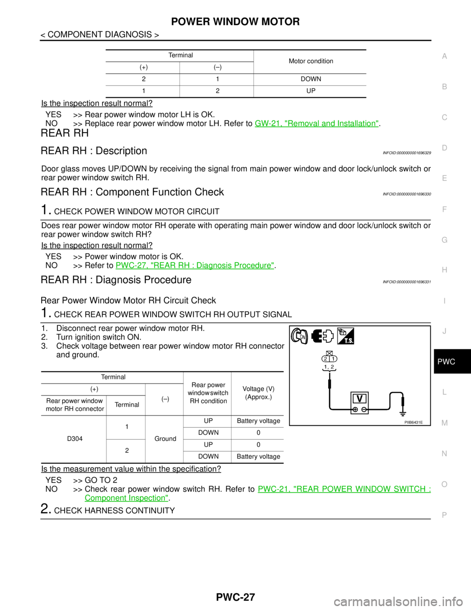
3. Check voltage between rear power window motor RH connector
and ground.
Is the measurement value within the specification?
YES >> GO TO 2
NO >> Check rear power window switch RH. Refer to PWC-21, "
REAR POWER WINDOW SWITCH :
Component Inspection".
2. CHECK HARNESS CONTINUITY
Te r m i n a l
Motor condition
(+) (–)
21 DOWN
12 UP
Te r m i n a l
Rear power
window switch
RH conditionVoltage (V)
(Approx.) (+)
(–)
Rear power window
motor RH connectorTe r m i n a l
D3041
GroundUP Battery voltage
DOWN 0
2UP 0
DOWN Battery voltage
PIIB6431E
Page 4489 of 5883
PWC-28
< COMPONENT DIAGNOSIS >
POWER WINDOW MOTOR
1. Turn ignition switch OFF.
2. Disconnect rear power window switch RH.
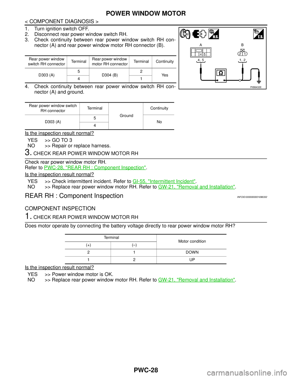
3. Check continuity between rear power window switch RH con-
nector (A) and rear power window motor RH connector (B).
4. Check continuity between rear power window switch RH con-
nector (A) and ground.
Is the inspection result normal?
YES >> GO TO 3
NO >> Repair or replace harness.
3. CHECK REAR POWER WINDOW MOTOR RH
Check rear power window motor RH.
Refer to PWC-28, "
REAR RH : Component Inspection".
Is the inspection result normal?
YES >> Check intermittent incident. Refer to GI-55, "Intermittent Incident".
NO >> Replace rear power window motor RH. Refer to GW-21, "
Removal and Installation".
REAR RH : Component InspectionINFOID:0000000001696332
COMPONENT INSPECTION
1. CHECK REAR POWER WINDOW MOTOR RH
Does motor operate by connecting the battery voltage directly to rear power window motor RH?
Is the inspection result normal?
YES >> Power window motor is OK.
NO >> Replace rear power window motor RH. Refer to GW-21, "
Removal and Installation".
Rear power window
switch RH connectorTe r m i n a lRear power window
motor RH connectorTerminal Continuity
D303 (A)5
D304 (B)2
Ye s
41
Rear power window switch
RH connectorTerminal
GroundContinuity
D303 (A)5
No
4
PIIB6432E
Te r m i n a l
Motor condition
(+) (–)
21 DOWN
12 UP
Page 4490 of 5883
ENCODER
PWC-29
< COMPONENT DIAGNOSIS >
C
D
E
F
G
H
I
J
L
MA
B
PWC
N
O
P
ENCODER
DRIVER SIDE
DRIVER SIDE : DescriptionINFOID:0000000001696333
Detects condition of the front power window motor (driver side) operation and transmits to main power window
and door lock/unlock switch as pulse signal.
DRIVER SIDE : Component Function CheckINFOID:0000000001696334
1. CHECK ENCODER OPERATION
Does front door motor (driver side) perform AUTO open/close operation normally with main power window and
door lock/unlock switch?
Is the inspection result normal?
YES >> Encoder operation is OK.
NO >> Refer to PWC-29, "
DRIVER SIDE : Diagnosis Procedure"
DRIVER SIDE : Diagnosis ProcedureINFOID:0000000001696335
Encoder Circuit Check
1. CHECK ENCODER OPERATION
1. Connect front power window motor (driver side).
2. Turn ignition switch ON.
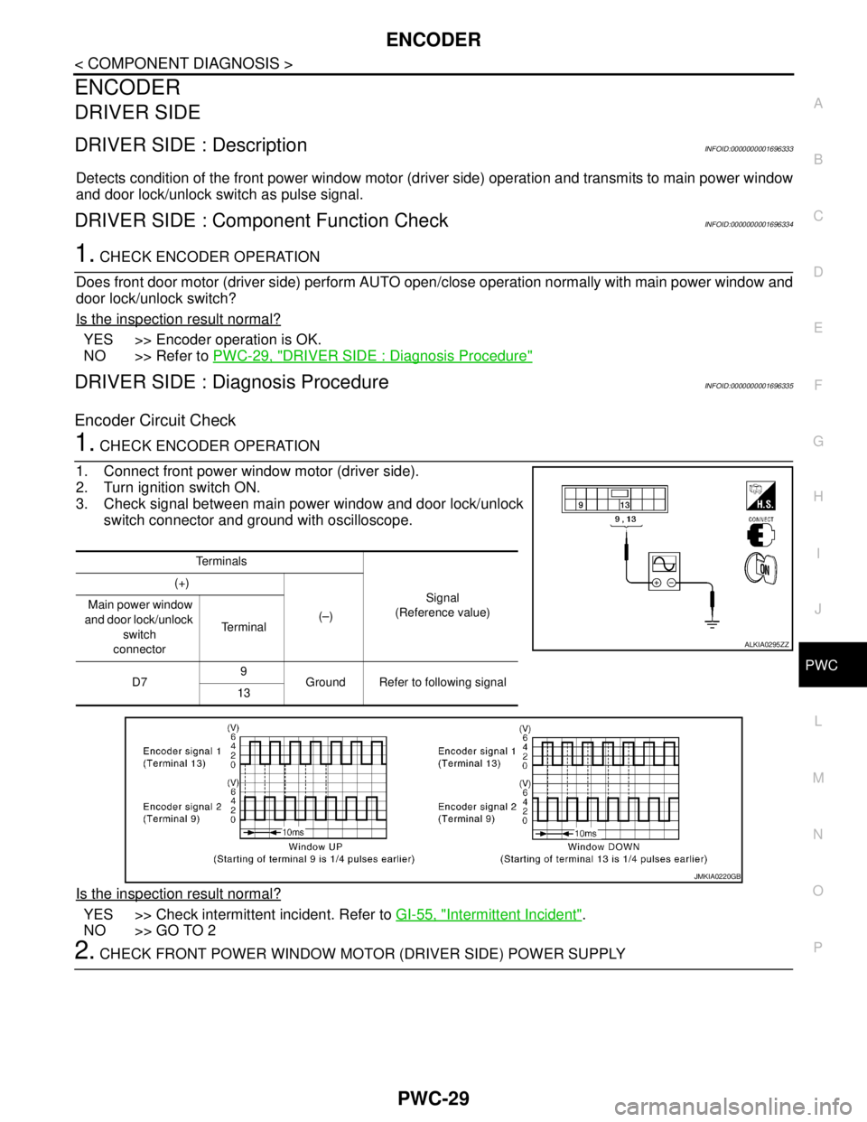
3. Check signal between main power window and door lock/unlock
switch connector and ground with oscilloscope.
Is the inspection result normal?
YES >> Check intermittent incident. Refer to GI-55, "Intermittent Incident".
NO >> GO TO 2
2. CHECK FRONT POWER WINDOW MOTOR (DRIVER SIDE) POWER SUPPLY
Te r m i n a l s
Signal
(Reference value) (+)
(–) Main power window
and door lock/unlock
switch
connectorTe r m i n a l
D79
Ground Refer to following signal
13
ALKIA0295ZZ
JMKIA0220GB
Page 4491 of 5883
PWC-30
< COMPONENT DIAGNOSIS >
ENCODER
1. Turn ignition switch ON.
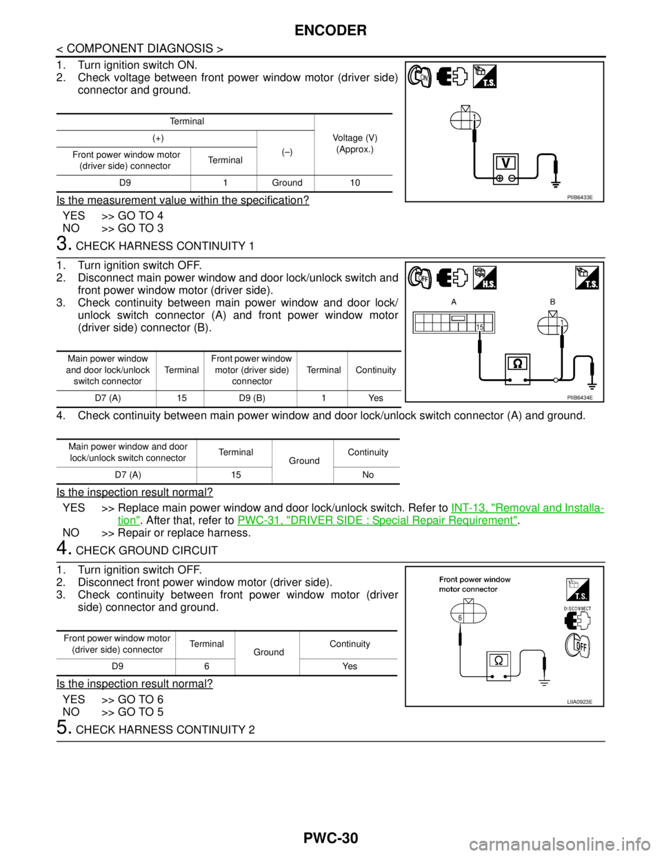
2. Check voltage between front power window motor (driver side)
connector and ground.
Is the measurement value within the specification?
YES >> GO TO 4
NO >> GO TO 3
3. CHECK HARNESS CONTINUITY 1
1. Turn ignition switch OFF.
2. Disconnect main power window and door lock/unlock switch and
front power window motor (driver side).
3. Check continuity between main power window and door lock/
unlock switch connector (A) and front power window motor
(driver side) connector (B).
4. Check continuity between main power window and door lock/unlock switch connector (A) and ground.
Is the inspection result normal?
YES >> Replace main power window and door lock/unlock switch. Refer to INT-13, "Removal and Installa-
tion". After that, refer to PWC-31, "DRIVER SIDE : Special Repair Requirement".
NO >> Repair or replace harness.
4. CHECK GROUND CIRCUIT
1. Turn ignition switch OFF.
2. Disconnect front power window motor (driver side).
3. Check continuity between front power window motor (driver
side) connector and ground.
Is the inspection result normal?
YES >> GO TO 6
NO >> GO TO 5
5. CHECK HARNESS CONTINUITY 2
Te r m i n a l
Voltage (V)
(Approx.) (+)
(–)
Front power window motor
(driver side) connectorTe r m i n a l
D9 1 Ground 10
PIIB6433E
Main power window
and door lock/unlock
switch connectorTe r m i n a lFront power window
motor (driver side)
connectorTerminal Continuity
D7 (A) 15 D9 (B) 1 Yes
Main power window and door
lock/unlock switch connectorTe r m i n a l
GroundContinuity
D7 (A) 15 No
PIIB6434E
Front power window motor
(driver side) connectorTerminal
GroundContinuity
D9 6 Yes
LIIA0923E
Page 4492 of 5883
ENCODER
PWC-31
< COMPONENT DIAGNOSIS >
C
D
E
F
G
H
I
J
L
MA
B
PWC
N
O
P
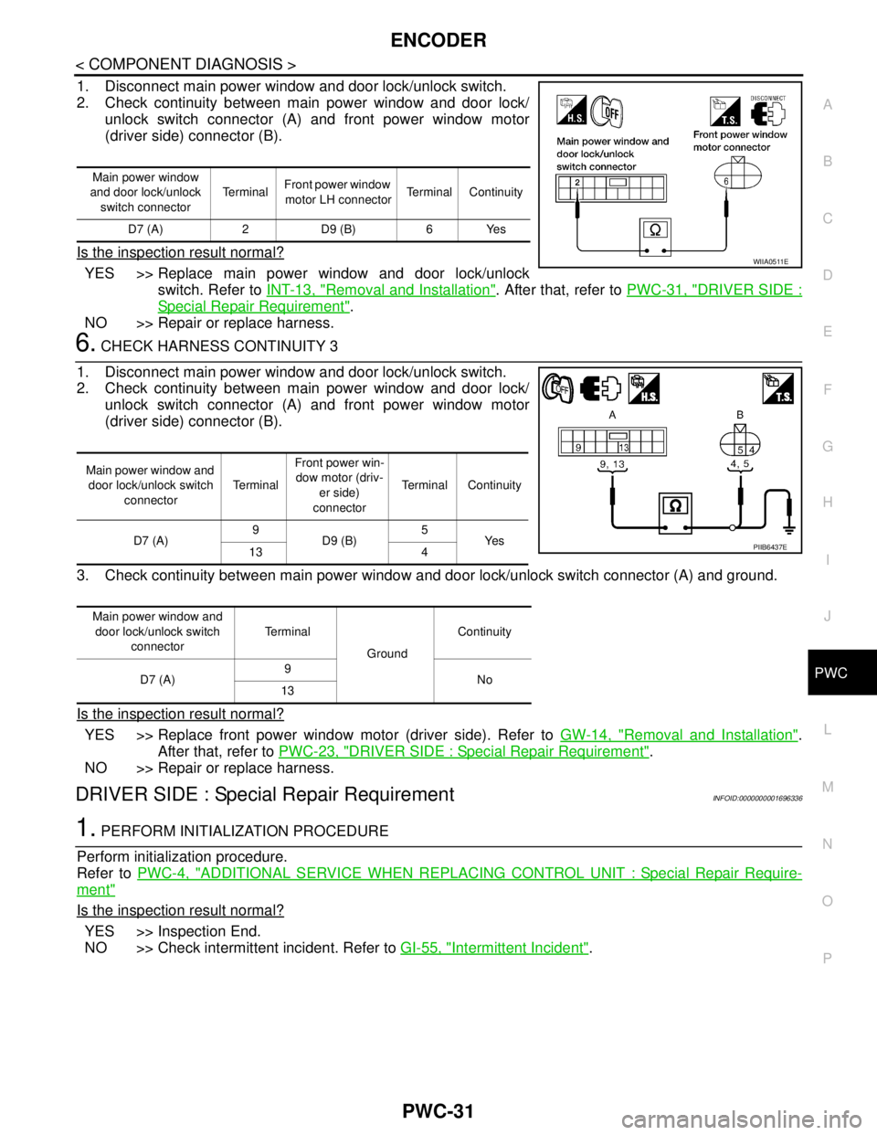
1. Disconnect main power window and door lock/unlock switch.
2. Check continuity between main power window and door lock/
unlock switch connector (A) and front power window motor
(driver side) connector (B).
Is the inspection result normal?
YES >> Replace main power window and door lock/unlock
switch. Refer to INT-13, "
Removal and Installation". After that, refer to PWC-31, "DRIVER SIDE :
Special Repair Requirement".
NO >> Repair or replace harness.
6. CHECK HARNESS CONTINUITY 3
1. Disconnect main power window and door lock/unlock switch.
2. Check continuity between main power window and door lock/
unlock switch connector (A) and front power window motor
(driver side) connector (B).
3. Check continuity between main power window and door lock/unlock switch connector (A) and ground.
Is the inspection result normal?
YES >> Replace front power window motor (driver side). Refer to GW-14, "Removal and Installation".
After that, refer to PWC-23, "
DRIVER SIDE : Special Repair Requirement".
NO >> Repair or replace harness.
DRIVER SIDE : Special Repair RequirementINFOID:0000000001696336
1. PERFORM INITIALIZATION PROCEDURE
Perform initialization procedure.
Refer to PWC-4, "
ADDITIONAL SERVICE WHEN REPLACING CONTROL UNIT : Special Repair Require-
ment"
Is the inspection result normal?
YES >> Inspection End.
NO >> Check intermittent incident. Refer to GI-55, "
Intermittent Incident".
Main power window
and door lock/unlock
switch connectorTe r m i n a lFront power window
motor LH connectorTerminal Continuity
D7 (A) 2 D9 (B) 6 Yes
WIIA0511E
Main power window and
door lock/unlock switch
connectorTe r m i n a lFront power win-
dow motor (driv-
er side)
connectorTerminal Continuity
D7 (A)9
D9 (B)5
Ye s
13 4
Main power window and
door lock/unlock switch
connectorTe r m i n a l
GroundContinuity
D7 (A)9
No
13
PIIB6437E
Page 4495 of 5883
PWC-34
< COMPONENT DIAGNOSIS >
POWER WINDOW LOCK SWITCH
POWER WINDOW LOCK SWITCH
DescriptionINFOID:0000000001696341
Ground circuit of main power window and door lock/unlock switch shuts off if power window lock switch of
main power window and door lock/unlock switch is operated. This inhibits all operation, except for the main
switch.
Component Function CheckINFOID:0000000001696342
1. CHECK POWER WINDOW LOCK SIGNAL
Exchanges for a normal main power window and door lock/unlock switch, and operation is checked.
Does power window lock operate?
YES >> Replace main power window and door lock/unlock switch. Refer to INT-13, "Removal and Installa-
tion". After that, PWC-4, "ADDITIONAL SERVICE WHEN REPLACING CONTROL UNIT : Special
Repair Requirement"
NO >> Check condition of harness and connector.
Special Repair RequirementINFOID:0000000001696343
1. PERFORM INITIALIZATION PROCEDURE
Perform initialization procedure.
Refer to PWC-4, "
ADDITIONAL SERVICE WHEN REPLACING CONTROL UNIT : Special Repair Require-
ment".
Is the inspection result normal?
YES >> Inspection end.
NO >> Check intermittent incident. Refer to GI-55, "
Intermittent Incident".
Page 4497 of 5883
PWC-36
< ECU DIAGNOSIS >
POWER WINDOW MAIN SWITCH
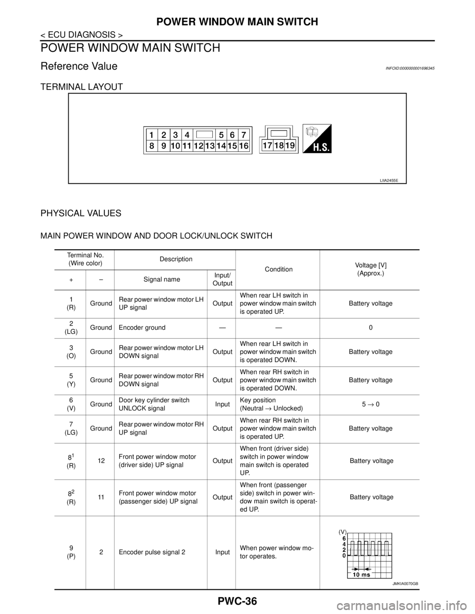
POWER WINDOW MAIN SWITCH
Reference Value INFOID:0000000001696345
TERMINAL LAYOUT
PHYSICAL VALUES
MAIN POWER WINDOW AND DOOR LOCK/UNLOCK SWITCH
LIIA2455E
Te r m i n a l N o .
(Wire color)Description
ConditionVoltage [V]
(Approx.)
+ – Signal name Input/
Output
1
(R)GroundRear power window motor LH
UP signalOutputWhen rear LH switch in
power window main switch
is operated UP.Battery voltage
2
(LG)Ground Encoder ground — — 0
3
(O)GroundRear power window motor LH
DOWN signalOutputWhen rear LH switch in
power window main switch
is operated DOWN.Battery voltage
5
(Y)GroundRear power window motor RH
DOWN signalOutputWhen rear RH switch in
power window main switch
is operated DOWN.Battery voltage
6
(V)GroundDoor key cylinder switch
UNLOCK signalInputKey position
(Neutral → Unlocked)5 → 0
7
(LG)GroundRear power window motor RH
UP signalOutputWhen rear RH switch in
power window main switch
is operated UP.Battery voltage
8
1
(R)12Front power window motor
(driver side) UP signalOutputWhen front (driver side)
switch in power window
main switch is operated
UP. Battery voltage
8
2
(R)11Front power window motor
(passenger side) UP signalOutputWhen front (passenger
side) switch in power win-
dow main switch is operat-
ed UP. Battery voltage
9
(P)2 Encoder pulse signal 2 InputWhen power window mo-
tor operates.
JMKIA0070GB
Page 4498 of 5883
POWER WINDOW MAIN SWITCH
PWC-37
< ECU DIAGNOSIS >
C
D
E
F
G
H
I
J
L
MA
B
PWC
N
O
P
1: LHD
2: RHD10
(L)Ground RAP signal InputIGN SW ON Battery voltage
Within 45 second after ig-
nition switch is turned to
OFF.Battery voltage
When driver side or pas-
senger side door is opened
during retained power op-
eration.0
11
1
(GR)8Front power window motor
(driver side) DOWN signalOutputWhen front (driver side)
switch in power window
main switch is operated
DOWN. Battery voltage
11
2
(SB)8Front power window motor
(passenger side) DOWN sig-
nalOutputWhen front (passenger
side) switch in power win-
dow main switch is operat-
ed DOWN. Battery voltage
12
1
(SB)16Front power window motor
(passenger side) DOWN sig-
nalOutputWhen front (passenger
side) switch in power win-
dow main switch is operat-
ed DOWN. Battery voltage
12
2
(GR)16Front power window motor
(driver side) DOWN signalOutputWhen front (driver side)
switch in power window
main switch is operated
DOWN. Battery voltage
13
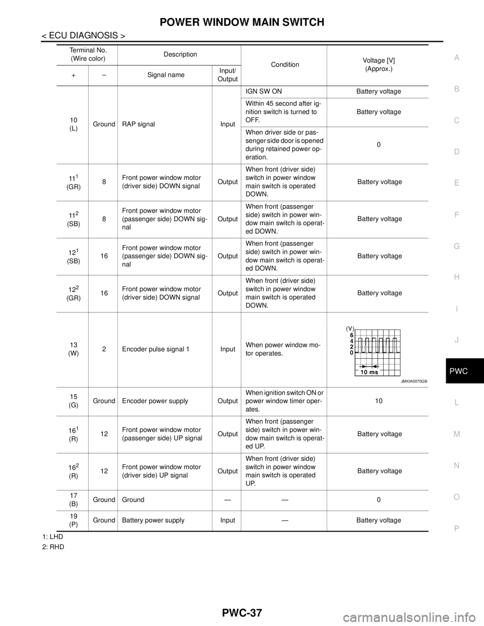
(W)2 Encoder pulse signal 1 InputWhen power window mo-
tor operates.
15
(G)Ground Encoder power supply OutputWhen ignition switch ON or
power window timer oper-
ates.10
16
1
(R)12Front power window motor
(passenger side) UP signalOutputWhen front (passenger
side) switch in power win-
dow main switch is operat-
ed UP. Battery voltage
16
2
(R)12Front power window motor
(driver side) UP signalOutputWhen front (driver side)
switch in power window
main switch is operated
UP. Battery voltage
17
(B)Ground Ground — — 0
19
(P)Ground Battery power supply Input — Battery voltage Te r m i n a l N o .
(Wire color)Description
ConditionVoltage [V]
(Approx.)
+ – Signal name Input/
Output
JMKIA0070GB