2007 NISSAN TIIDA fuel cap release
[x] Cancel search: fuel cap releasePage 2810 of 5883
![NISSAN TIIDA 2007 Service Repair Manual FUEL INJECTOR AND FUEL TUBE
EM-163
< ON-VEHICLE REPAIR >[MR18DE]
C
D
E
F
G
H
I
J
K
L
MA
EM
N
P O
3. Disconnect fuel feed hose from hose clamp.
NOTE:
There is no fuel return path.
4. With the sleeve si NISSAN TIIDA 2007 Service Repair Manual FUEL INJECTOR AND FUEL TUBE
EM-163
< ON-VEHICLE REPAIR >[MR18DE]
C
D
E
F
G
H
I
J
K
L
MA
EM
N
P O
3. Disconnect fuel feed hose from hose clamp.
NOTE:
There is no fuel return path.
4. With the sleeve si](/manual-img/5/57395/w960_57395-2809.png)
FUEL INJECTOR AND FUEL TUBE
EM-163
< ON-VEHICLE REPAIR >[MR18DE]
C
D
E
F
G
H
I
J
K
L
MA
EM
N
P O
3. Disconnect fuel feed hose from hose clamp.
NOTE:
There is no fuel return path.
4. With the sleeve side of quick connector release facing quick connector, install quick connector release
onto fuel tube.
5. Insert quick connector release into quick connector until sleeve
contacts and goes no further. Hold quick connector release on
that position.
CAUTION:
Inserting quick connector release hard will not disconnect
quick connector. Hold quick connector release where it
contacts and goes no further.
6. Draw and pull out quick connector straight from fuel tube.
CAUTION:
Pull quick connector holding “A” position.
Do not pull with lateral force applied. O-ring inside quick connector may be damaged.
Prepare container and cloth beforehand as fuel will leak out.
Avoid fire and sparks.
Keep parts away from heat source. Especially, be careful when welding is performed around
them.
Do not expose parts to battery electrolyte or other acids.
Do not bend or twist connection between quick connector and fuel feed hose during installation/
removal.
To keep clean the connecting portion and to avoid dam-
age and foreign materials, cover them completely with
plastic bags or something similar.
7. Remove intake manifold. Refer to EM-156
.
1 : Quick connector cap
PBIC3771E
KBIA0702E
PBIC2205E
Page 2899 of 5883
![NISSAN TIIDA 2007 Service Repair Manual EM-252
< PRECAUTION >[K9K]
PRECAUTIONS
3. Disconnect both battery cables. The steering lock will remain released and the steering wheel can be
rotated.
4. Perform the necessary repair operation.
5. Wh NISSAN TIIDA 2007 Service Repair Manual EM-252
< PRECAUTION >[K9K]
PRECAUTIONS
3. Disconnect both battery cables. The steering lock will remain released and the steering wheel can be
rotated.
4. Perform the necessary repair operation.
5. Wh](/manual-img/5/57395/w960_57395-2898.png)
EM-252
< PRECAUTION >[K9K]
PRECAUTIONS
3. Disconnect both battery cables. The steering lock will remain released and the steering wheel can be
rotated.
4. Perform the necessary repair operation.
5. When the repair work is completed, return the ignition switch to the ″LOCK″ position before connecting
the battery cables. (At this time, the steering lock mechanism will engage.)
6. Perform a self-diagnosis check of all control units using CONSULT-III.
Precaution for Drain CoolantINFOID:0000000001381450
Drain coolant when engine is cooled.
Precaution for Disconnecting Fuel PipingINFOID:0000000001381451
Before starting work, make sure no fire or spark producing items are in the work area.
Release fuel pressure before disassembly.
After disconnecting pipes, plug openings to stop fuel leakage.
Precaution for Removal and DisassemblyINFOID:0000000001381452
When instructed to use special service tools, use the specified tools. Always be careful to work safely, avoid
forceful or uninstructed operations.
Exercise maximum care to avoid damage to mating or sliding surfaces.
Cover openings of engine system with tape or the equivalent, if necessary, to seal out foreign materials.
Mark and arrange disassembly parts in an organized way for easy troubleshooting and re-assembly.
When loosening nuts and bolts, as a basic rule, start with the one furthest outside, then the one diagonally
opposite, and so on. If the order of loosening is specified, do exactly as specified.
Precaution for Inspection, Repair and ReplacementINFOID:0000000001381453
Before repairing or replacing, thoroughly inspect parts. Inspect new replacement parts in the same way, and
replace if necessary.
Precaution for Assembly and InstallationINFOID:0000000001381454
Use torque wrench to tighten bolts or nuts to specified value.
When tightening nuts and bolts, as a basic rule, equally tighten in several different steps starting with the
ones in center, then ones on inside and outside diagonally in this order. If the order of tightening is specified,
do exactly same as specified.
Replace with new gasket, packing, oil seal or O-ring.
Thoroughly wash, clean, and air-blow each part. Carefully check oil or coolant passages for any restriction
and blockage.
Avoid damaging sliding or mating surfaces. Completely remove foreign materials such as cloth lint or dust.
Before assemble, spread the oil on sliding surfaces well.
Release air within route when refilling after draining coolant.
Before starting engine, apply fuel pressure to fuel lines with turning ignition switch ON (with engine stopped).
Then make sure that there are no leaks at fuel line connections.
After repairing, start engine and increase engine speed to check coolant, fuel, oil, and exhaust systems for
leakage.
Parts Requiring Angular TighteningINFOID:0000000001381455
Use an angle wrench for the final tightening of the following engine parts.
- Cylinder head bolts
- Lower cylinder block bolts
- Connecting rod cap bolts
- Crankshaft pulley bolt (No angle wrench is required as the bolt flange is provided with notches for angular
tightening)
Do not use a torque value for final tightening.
The torque value for these parts are for a preliminary step.
Ensure thread and seat surfaces are clean and coated with engine oil.
Page 3164 of 5883
FL-4
< ON-VEHICLE MAINTENANCE >
FUEL SYSTEM
ON-VEHICLE MAINTENANCE
FUEL SYSTEM
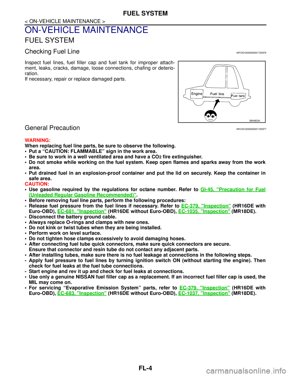
Checking Fuel LineINFOID:0000000001722976
Inspect fuel lines, fuel filler cap and fuel tank for improper attach-
ment, leaks, cracks, damage, loose connections, chafing or deterio-
ration.
If necessary, repair or replace damaged parts.
General PrecautionINFOID:0000000001722977
WARNING:
When replacing fuel line parts, be sure to observe the following.
Put a “CAUTION: FLAMMABLE” sign in the work area.
Be sure to work in a well ventilated area and have a CO
2 fire extinguisher.
Do not smoke while working on the fuel system. Keep open flames and sparks away from the work
area.
Put drained fuel in an explosion-proof container and put the lid on securely. Keep the container in
safe area.
CAUTION:
Use gasoline required by the regulations for octane number. Refer to GI-45, "
Precaution for Fuel
(Unleaded Regular Gasoline Recommended)".
Before removing fuel line parts, perform the following procedures:
- Release fuel pressure from the fuel lines if necessary. Refer to EC-379, "
Inspection" (HR16DE with
Euro-OBD), EC-681, "
Inspection" (HR16DE without Euro-OBD), EC-1035, "Inspection" (MR18DE).
- Disconnect the battery ground cable.
Always replace O-rings and clamps with new ones.
Do not kink or twist tubes when they are being installed.
Perform work on level surface.
Do not tighten hose clamps excessively to avoid damaging hoses.
After connecting fuel tube quick connectors, make sure quick connectors are secure.
Ensure that connector and resin tube do not contact any adjacent parts.
After installing tubes, make sure there is no fuel leakage at connections in the following steps.
- Apply fuel pressure to fuel lines by turning ignition switch ON (without starting the engine). Then
check for fuel leaks at the fuel tube connections.
- Start engine and rev it up and check for fuel leaks at connections.
Use only a genuine NISSAN fuel filler cap as a replacement. If an incorrect fuel filler cap is used, the
MIL may come on.
For servicing “Evaporative Emission System” parts, refer to EC-379, "
Inspection" (HR16DE with
Euro-OBD), EC-683, "
Inspection" (HR16DE without Euro-OBD), EC-1037, "Inspection" (MR18DE).
SMA803A
Page 3166 of 5883
FL-6
< ON-VEHICLE REPAIR >
FUEL LEVEL SENSOR UNIT, FUEL FILTER AND FUEL PUMP ASSEMBLY
b. Disconnect fuel filler hose from fuel filler tube. Refer to FL-10, "HR16DE, HR18DE".
c. Insert fuel tubing into fuel tank through fuel filler hose to drain fuel from fuel tank.
2. Release the fuel pressure from the fuel lines. Refer to EC-377, "
Inspection" (HR16DE with EURO-OBD),
EC-681, "
Inspection" (HR16DE without EURO-OBD), EC-1035, "Inspection" (MR18DE).
3. Open fuel filler lid.
4. Open fuel door and unscrew the fuel filler cap to release the pressure inside the fuel tank.
5. Remove rear seat bottom. Refer to SE-18, "
Removal and Installation".
6. Turn the four retainers 90° in a clockwise direction and remove the fuel pump inspection hole cover.
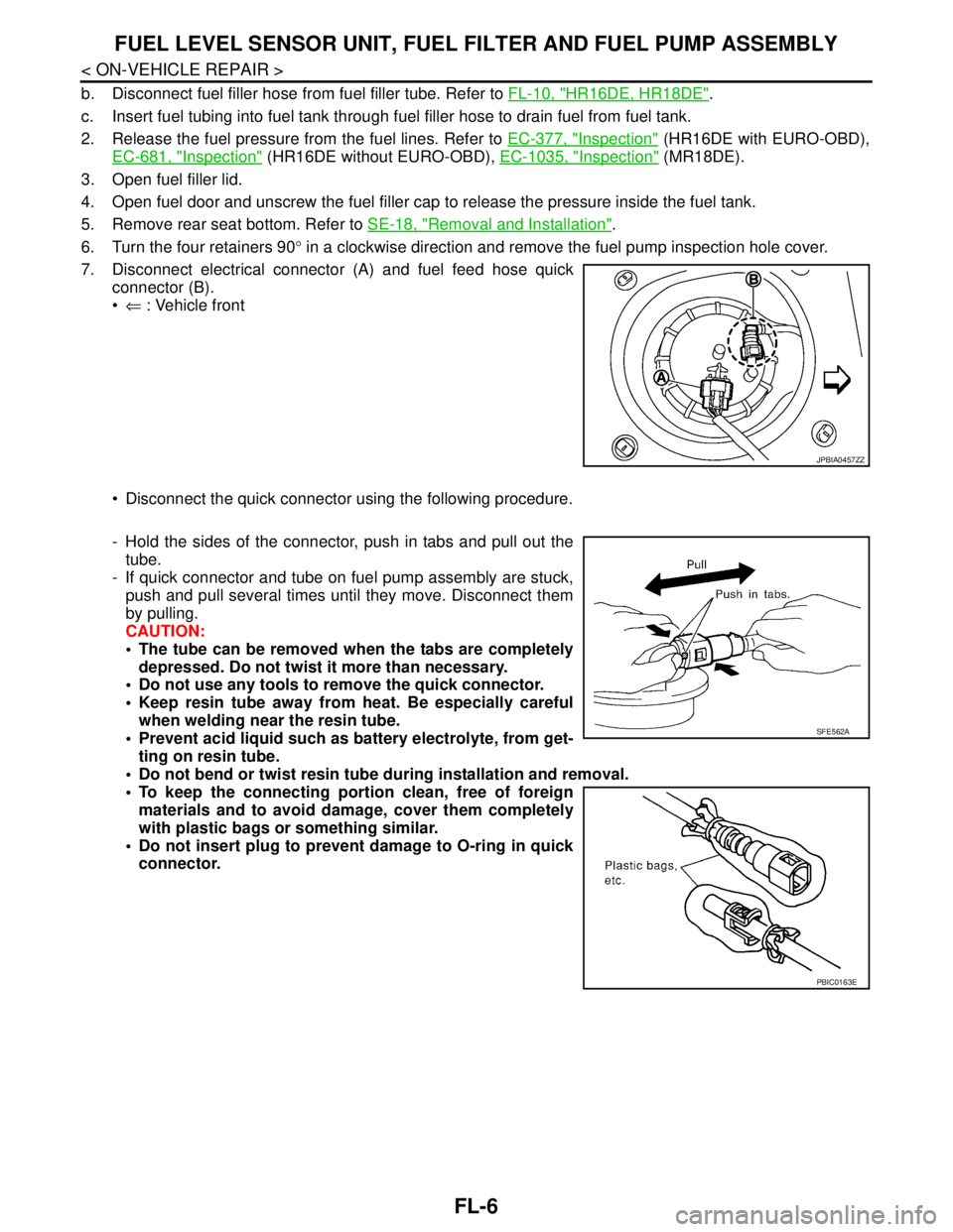
7. Disconnect electrical connector (A) and fuel feed hose quick
connector (B).
⇐ : Vehicle front
Disconnect the quick connector using the following procedure.
- Hold the sides of the connector, push in tabs and pull out the
tube.
- If quick connector and tube on fuel pump assembly are stuck,
push and pull several times until they move. Disconnect them
by pulling.
CAUTION:
The tube can be removed when the tabs are completely
depressed. Do not twist it more than necessary.
Do not use any tools to remove the quick connector.
Keep resin tube away from heat. Be especially careful
when welding near the resin tube.
Prevent acid liquid such as battery electrolyte, from get-
ting on resin tube.
Do not bend or twist resin tube during installation and removal.
To keep the connecting portion clean, free of foreign
materials and to avoid damage, cover them completely
with plastic bags or something similar.
Do not insert plug to prevent damage to O-ring in quick
connector.
JPBIA0457ZZ
SFE562A
PBIC0163E
Page 3169 of 5883
FUEL LEVEL SENSOR UNIT, FUEL FILTER AND FUEL PUMP ASSEMBLY
FL-9
< ON-VEHICLE REPAIR >
C
D
E
F
G
H
I
J
K
L
MA
FL
N
P O
1. Disconnect battery ground cable.
2. Open fuel filler lid and filler cap to release the pressure inside the fuel tank.
3. Remove rear seat cushion. Refer to SE-18, "
Removal and Installation".
4. Remove the fuel pump inspection hole cover.
5. Disconnect electrical connector.
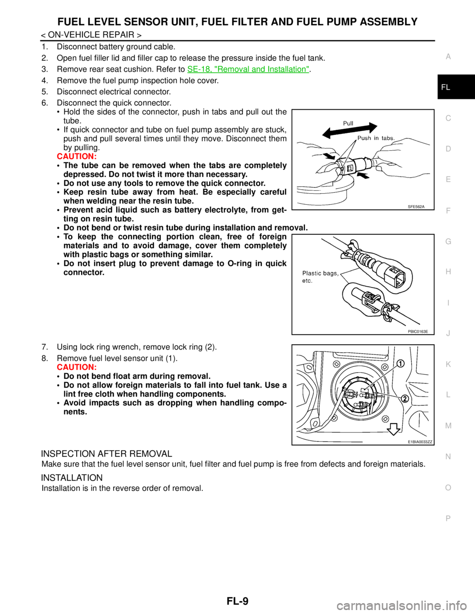
6. Disconnect the quick connector.
Hold the sides of the connector, push in tabs and pull out the
tube.
If quick connector and tube on fuel pump assembly are stuck,
push and pull several times until they move. Disconnect them
by pulling.
CAUTION:
The tube can be removed when the tabs are completely
depressed. Do not twist it more than necessary.
Do not use any tools to remove the quick connector.
Keep resin tube away from heat. Be especially careful
when welding near the resin tube.
Prevent acid liquid such as battery electrolyte, from get-
ting on resin tube.
Do not bend or twist resin tube during installation and removal.
To keep the connecting portion clean, free of foreign
materials and to avoid damage, cover them completely
with plastic bags or something similar.
Do not insert plug to prevent damage to O-ring in quick
connector.
7. Using lock ring wrench, remove lock ring (2).
8. Remove fuel level sensor unit (1).
CAUTION:
Do not bend float arm during removal.
Do not allow foreign materials to fall into fuel tank. Use a
lint free cloth when handling components.
Avoid impacts such as dropping when handling compo-
nents.
INSPECTION AFTER REMOVAL
Make sure that the fuel level sensor unit, fuel filter and fuel pump is free from defects and foreign materials.
INSTALLATION
Installation is in the reverse order of removal.
SFE562A
PBIC0163E
E1BIA0033ZZ
Page 4274 of 5883
MA-34
< ON-VEHICLE MAINTENANCE >
ENGINE MAINTENANCE (MR18DE)
RADIATOR : Checking Radiator Cap
INFOID:0000000001730871
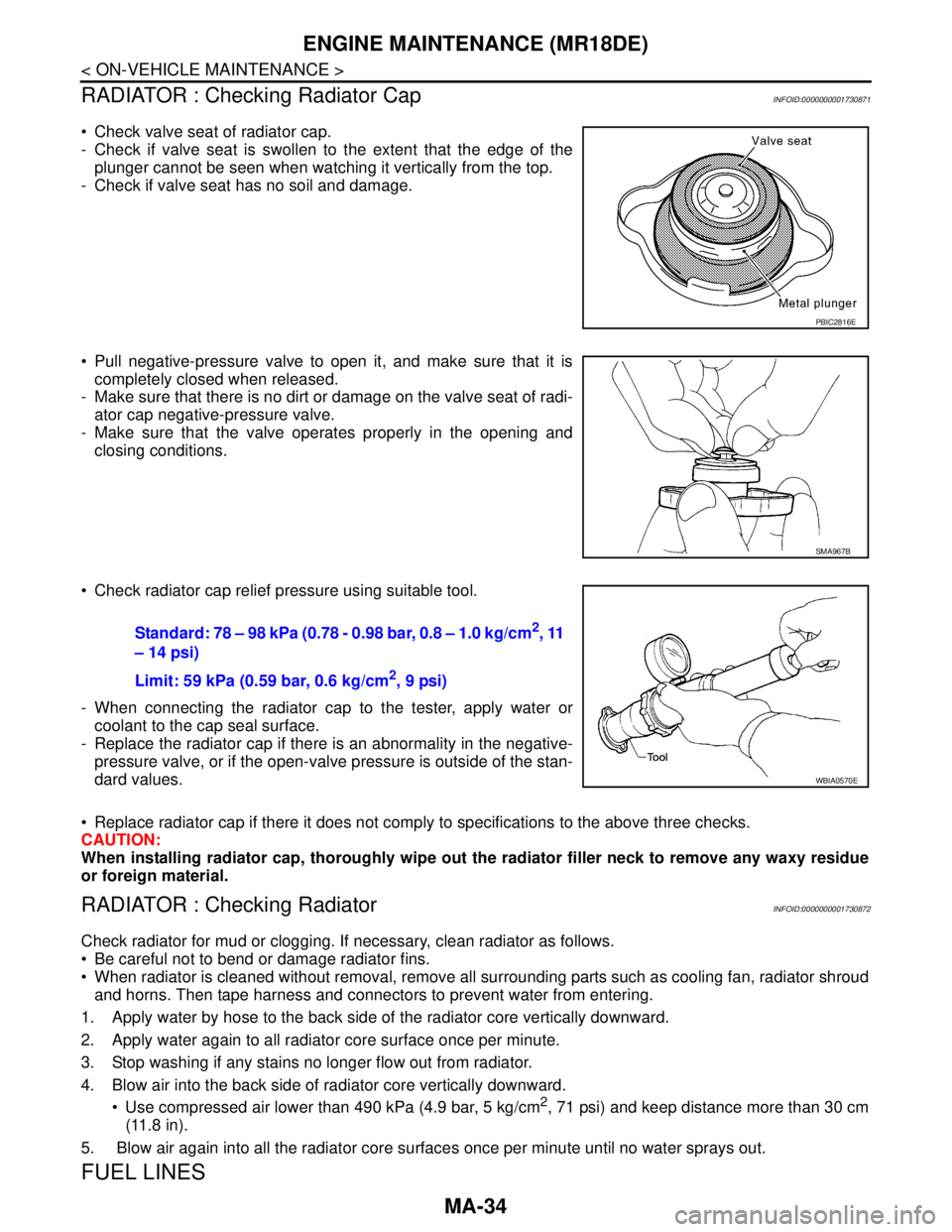
Check valve seat of radiator cap.
- Check if valve seat is swollen to the extent that the edge of the
plunger cannot be seen when watching it vertically from the top.
- Check if valve seat has no soil and damage.
Pull negative-pressure valve to open it, and make sure that it is
completely closed when released.
- Make sure that there is no dirt or damage on the valve seat of radi-
ator cap negative-pressure valve.
- Make sure that the valve operates properly in the opening and
closing conditions.
Check radiator cap relief pressure using suitable tool.
- When connecting the radiator cap to the tester, apply water or
coolant to the cap seal surface.
- Replace the radiator cap if there is an abnormality in the negative-
pressure valve, or if the open-valve pressure is outside of the stan-
dard values.
Replace radiator cap if there it does not comply to specifications to the above three checks.
CAUTION:
When installing radiator cap, thoroughly wipe out the radiator filler neck to remove any waxy residue
or foreign material.
RADIATOR : Checking RadiatorINFOID:0000000001730872
Check radiator for mud or clogging. If necessary, clean radiator as follows.
Be careful not to bend or damage radiator fins.
When radiator is cleaned without removal, remove all surrounding parts such as cooling fan, radiator shroud
and horns. Then tape harness and connectors to prevent water from entering.
1. Apply water by hose to the back side of the radiator core vertically downward.
2. Apply water again to all radiator core surface once per minute.
3. Stop washing if any stains no longer flow out from radiator.
4. Blow air into the back side of radiator core vertically downward.
Use compressed air lower than 490 kPa (4.9 bar, 5 kg/cm
2, 71 psi) and keep distance more than 30 cm
(11.8 in).
5. Blow air again into all the radiator core surfaces once per minute until no water sprays out.
FUEL LINES
PBIC2816E
SMA967B
Standard: 78 – 98 kPa (0.78 - 0.98 bar, 0.8 – 1.0 kg/cm2, 11
– 14 psi)
Limit: 59 kPa (0.59 bar, 0.6 kg/cm
2, 9 psi)
WBIA0570E
Page 4285 of 5883
ENGINE MAINTENANCE (K9K)
MA-45
< ON-VEHICLE MAINTENANCE >
C
D
E
F
G
H
I
J
K
L
MB
MAN
OA
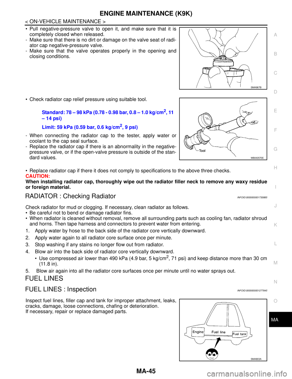
Pull negative-pressure valve to open it, and make sure that it is
completely closed when released.
- Make sure that there is no dirt or damage on the valve seat of radi-
ator cap negative-pressure valve.
- Make sure that the valve operates properly in the opening and
closing conditions.
Check radiator cap relief pressure using suitable tool.
- When connecting the radiator cap to the tester, apply water or
coolant to the cap seal surface.
- Replace the radiator cap if there is an abnormality in the negative-
pressure valve, or if the open-valve pressure is outside of the stan-
dard values.
Replace radiator cap if there it does not comply to specifications to the above three checks.
CAUTION:
When installing radiator cap, thoroughly wipe out the radiator filler neck to remove any waxy residue
or foreign material.
RADIATOR : Checking RadiatorINFOID:0000000001730885
Check radiator for mud or clogging. If necessary, clean radiator as follows.
Be careful not to bend or damage radiator fins.
When radiator is cleaned without removal, remove all surrounding parts such as cooling fan, radiator shroud
and horns. Then tape harness and connectors to prevent water from entering.
1. Apply water by hose to the back side of the radiator core vertically downward.
2. Apply water again to all radiator core surface once per minute.
3. Stop washing if any stains no longer flow out from radiator.
4. Blow air into the back side of radiator core vertically downward.
Use compressed air lower than 490 kPa (4.9 bar, 5 kg/cm
2, 71 psi) and keep distance more than 30 cm
(11.8 in).
5. Blow air again into all the radiator core surfaces once per minute until no water sprays out.
FUEL LINES
FUEL LINES : InspectionINFOID:0000000001277645
Inspect fuel lines, filler cap and tank for improper attachment, leaks,
cracks, damage, loose connections, chafing or deterioration.
If necessary, repair or replace damaged parts.
SMA967B
Standard: 78 – 98 kPa (0.78 - 0.98 bar, 0.8 – 1.0 kg/cm2, 11
– 14 psi)
Limit: 59 kPa (0.59 bar, 0.6 kg/cm
2, 9 psi)
WBIA0570E
SMA803A
Page 4328 of 5883
MWI
DIAGNOSIS SYSTEM (METER)
MWI-21
< FUNCTION DIAGNOSIS >
C
D
E
F
G
H
I
J
K
L
MB A
O
P
DIAGNOSIS SYSTEM (METER)
Diagnosis DescriptionINFOID:0000000001374681
SELF-DIAGNOSIS MODE
Self-diagnosis can check for continuity between meter control circuit and each meter (speedometer, tachom-
eter and fuel gauge).
Self-diagnosis can check for odo/trip meter and information display segment, low-fuel level warning lamp,
low water temperature indicator lamp, and high water temperature warning lamp.
NOTE:
This combination meter has no capability to perform on-board data checking and CONSULT type active tests
as seen in other Nissan combination meters. For additional combination meter diagnostic functions refer to
MWI-22, "
CONSULT-III Function (METER/M&A)".
OPERATION PROCEDURE
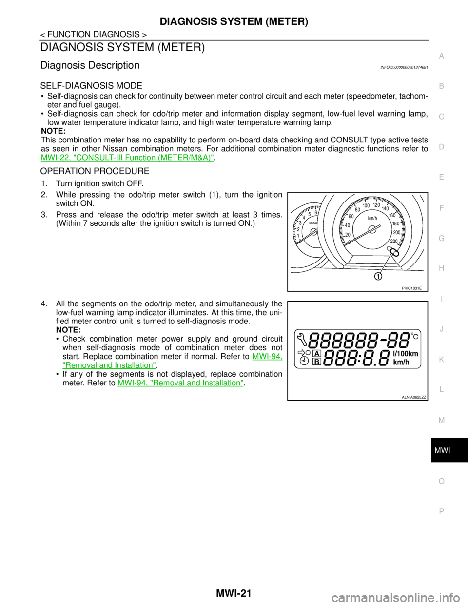
1. Turn ignition switch OFF.
2. While pressing the odo/trip meter switch (1), turn the ignition
switch ON.
3. Press and release the odo/trip meter switch at least 3 times.
(Within 7 seconds after the ignition switch is turned ON.)
4. All the segments on the odo/trip meter, and simultaneously the
low-fuel warning lamp indicator illuminates. At this time, the uni-
fied meter control unit is turned to self-diagnosis mode.
NOTE:
Check combination meter power supply and ground circuit
when self-diagnosis mode of combination meter does not
start. Replace combination meter if normal. Refer to MWI-94,
"Removal and Installation".
If any of the segments is not displayed, replace combination
meter. Refer to MWI-94, "
Removal and Installation".
PKIC1031E
ALNIA0625ZZ