2007 NISSAN TIIDA engine oil
[x] Cancel search: engine oilPage 2638 of 5883
![NISSAN TIIDA 2007 Service Repair Manual ENGINE SMOKES WHEN REVVED
EC-1289
< SYMPTOM DIAGNOSIS >[K9K]
C
D
E
F
G
H
I
J
K
L
MA
EC
N
P O
ENGINE SMOKES WHEN REVVED
DescriptionINFOID:0000000001162737
CHART 20: ENGINE SMOKES WHEN REVVED
Diagnosis NISSAN TIIDA 2007 Service Repair Manual ENGINE SMOKES WHEN REVVED
EC-1289
< SYMPTOM DIAGNOSIS >[K9K]
C
D
E
F
G
H
I
J
K
L
MA
EC
N
P O
ENGINE SMOKES WHEN REVVED
DescriptionINFOID:0000000001162737
CHART 20: ENGINE SMOKES WHEN REVVED
Diagnosis](/manual-img/5/57395/w960_57395-2637.png)
ENGINE SMOKES WHEN REVVED
EC-1289
< SYMPTOM DIAGNOSIS >[K9K]
C
D
E
F
G
H
I
J
K
L
MA
EC
N
P O
ENGINE SMOKES WHEN REVVED
DescriptionINFOID:0000000001162737
CHART 20: ENGINE SMOKES WHEN REVVED
Diagnosis ProcedureINFOID:0000000001162738
1.CHECK ENGINE OIL
Check the grade of engine oil. Refer to LU-26, "
Inspection".
Is the inspection result normal?
YES >> GO TO 2.
NO >> Replace engine oil. Refer to LU-27, "
Refilling"
2.CHECK ENGINE OIL LEVEL
Is the engine oil level correct?
Ye s o r N o
Yes >> GO TO 3.
No >> Top up the oil.
3.CHECK ECM POWER SUPPLY AND GROUND CIRCUIT
Check ECM power supply and ground circuit. Refer to EC-1133, "
Component Inspection".
Is the inspection result normal?
YES >> GO TO 4.
NO >> Repair or replace harness or connector.
4.CHECK WIRING HARNESS
Visually check the condition of the engine wiring harness.
Is the inspection result normal?
YES >> GO TO 5.
NO >> Repair or replace harness or connector.
5.CHECK MASS AIR FLOW SENSOR
Check mass air flow sensor. Refer to EC-1125, "
Component Inspection".
Is the inspection result normal?
YES >>INSPECTION END
NO >> Repair or replace.
Page 2643 of 5883
![NISSAN TIIDA 2007 Service Repair Manual EC-1294
< PRECAUTION >[K9K]
PRECAUTIONS
General Precautions
INFOID:0000000001162746
Always use a 12 volt battery as power source.
Do not attempt to disconnect battery cables while engine is
running. NISSAN TIIDA 2007 Service Repair Manual EC-1294
< PRECAUTION >[K9K]
PRECAUTIONS
General Precautions
INFOID:0000000001162746
Always use a 12 volt battery as power source.
Do not attempt to disconnect battery cables while engine is
running.](/manual-img/5/57395/w960_57395-2642.png)
EC-1294
< PRECAUTION >[K9K]
PRECAUTIONS
General Precautions
INFOID:0000000001162746
Always use a 12 volt battery as power source.
Do not attempt to disconnect battery cables while engine is
running.
Before connecting or disconnecting the ECM harness con-
nector, turn ignition switch OFF, wait 3 minutes and discon-
nect battery negative cable. Failure to do so may damage the
ECM because battery voltage is applied to ECM even if igni-
tion switch is turned OFF.
Before removing parts, turn ignition switch OFF and then dis-
connect battery negative cable.
Do not disassemble ECM.
When connecting ECM harness connector, fasten (A) it
securely with levers (1) as far as they will go as shown in the
figure.
-ECM (2)
-Loosen (B)
When connecting or disconnecting pin connectors into or
from ECM, take care not to damage pin terminals (bend or
break).
Make sure that there are not any bends or breaks on ECM pin
terminal, when connecting pin connectors.
Securely connect ECM harness connectors.
A poor connection can cause an extremely high (surge) volt-
age to develop in coil and condenser, thus resulting in dam-
age to IC's.
Keep engine control system harness at least 10cm (4 in) away
from adjacent harness, to prevent engine control system mal-
functions due to receiving external noise, degraded operation
of IC's, etc.
Keep engine control system parts and harness dry.
Handle mass air flow sensor carefully to avoid damage.
Do not disassemble mass air flow sensor.
Do not clean mass air flow sensor with any type of detergent.
Even a slight leak in the air intake system can cause serious incidents.
Do not shock or jar the camshaft position sensor, crankshaft position sensor.
SEF289H
MBIB1517E
MBIB1518E
SEF291H
Page 2648 of 5883

EM-1
ENGINE
C
D
E
F
G
H
I
J
K
L
M
SECTION EM
A
EM
N
O
P
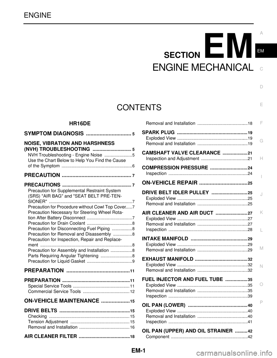
CONTENTS
ENGINE MECHANICAL
HR16DE
SYMPTOM DIAGNOSIS ...............................
5
NOISE, VIBRATION AND HARSHNESS
(NVH) TROUBLESHOOTING .............................
5
NVH Troubleshooting - Engine Noise .......................5
Use the Chart Below to Help You Find the Cause
of the Symptom .........................................................
6
PRECAUTION ...............................................7
PRECAUTIONS ...................................................7
Precaution for Supplemental Restraint System
(SRS) "AIR BAG" and "SEAT BELT PRE-TEN-
SIONER" ...................................................................
7
Precaution for Procedure without Cowl Top Cover ......7
Precaution Necessary for Steering Wheel Rota-
tion After Battery Disconnect .....................................
7
Precaution for Drain Coolant .....................................8
Precaution for Disconnecting Fuel Piping .................8
Precaution for Removal and Disassembly ................8
Precaution for Inspection, Repair and Replace-
ment ..........................................................................
8
Precaution for Assembly and Installation ..................8
Parts Requiring Angular Tightening ..........................8
Precaution for Liquid Gasket .....................................9
PREPARATION ...........................................11
PREPARATION ..................................................11
Special Service Tools ..............................................11
Commercial Service Tools ......................................12
ON-VEHICLE MAINTENANCE ....................15
DRIVE BELTS ....................................................15
Checking .................................................................15
Tension Adjustment ................................................15
Removal and Installation .........................................16
AIR CLEANER FILTER ......................................18
Removal and Installation .........................................18
SPARK PLUG ...................................................19
Exploded View .........................................................19
Removal and Installation .........................................19
CAMSHAFT VALVE CLEARANCE ..................21
Inspection and Adjustment ......................................21
COMPRESSION PRESSURE ...........................24
Inspection ................................................................24
ON-VEHICLE REPAIR .................................25
DRIVE BELT IDLER PULLEY ..........................25
Exploded View .........................................................25
Removal and Installation .........................................25
AIR CLEANER AND AIR DUCT .......................27
Exploded View .........................................................27
Removal and Installation .........................................27
Inspection ................................................................28
INTAKE MANIFOLD .........................................29
Exploded View .........................................................29
Removal and Installation .........................................29
EXHAUST MANIFOLD ......................................32
Exploded View .........................................................32
Removal and Installation .........................................32
FUEL INJECTOR AND FUEL TUBE ................35
Exploded View .........................................................35
Removal and Installation .........................................35
Inspection ................................................................39
OIL PAN (LOWER) ...........................................40
Exploded View .........................................................40
Removal and Installation .........................................40
Inspection ................................................................41
OIL PAN (UPPER) AND OIL STRAINER .........42
Component ..............................................................42
Page 2649 of 5883

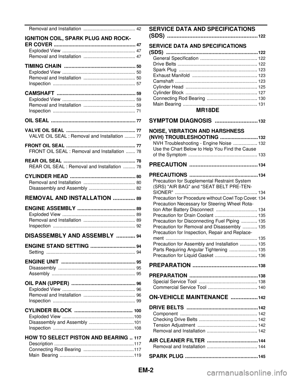
EM-2
Removal and Installation ........................................42
IGNITION COIL, SPARK PLUG AND ROCK-
ER COVER .........................................................
47
Exploded View ........................................................47
Removal and Installation ........................................47
TIMING CHAIN ..................................................50
Exploded View ........................................................50
Removal and Installation ........................................50
Inspection ...............................................................57
CAMSHAFT .......................................................59
Exploded View ........................................................59
Removal and Installation ........................................59
Inspection ...............................................................71
OIL SEAL ...........................................................77
VALVE OIL SEAL .....................................................77
VALVE OIL SEAL : Removal and Installation .........77
FRONT OIL SEAL .....................................................77
FRONT OIL SEAL : Removal and Installation ........78
REAR OIL SEAL .......................................................78
REAR OIL SEAL : Removal and Installation ..........78
CYLINDER HEAD ..............................................80
Removal and Installation ........................................80
Disassembly and Assembly ....................................82
REMOVAL AND INSTALLATION ...............89
ENGINE ASSEMBLY .........................................89
Exploded View ........................................................89
Removal and Installation ........................................89
Inspection ...............................................................92
DISASSEMBLY AND ASSEMBLY .............94
ENGINE STAND SETTING ................................94
Setting ....................................................................94
ENGINE UNIT ....................................................95
Disassembly ...........................................................95
Assembly ................................................................95
OIL PAN (UPPER) .............................................96
Exploded View ........................................................96
Removal and Installation ........................................96
Inspection ...............................................................99
CYLINDER BLOCK .........................................100
Exploded View .......................................................100
Disassembly and Assembly ...................................101
Inspection ..............................................................108
HOW TO SELECT PISTON AND BEARING ...117
Description .............................................................117
Connecting Rod Bearing .......................................117
Main Bearing .........................................................119
SERVICE DATA AND SPECIFICATIONS
(SDS) .........................................................
122
SERVICE DATA AND SPECIFICATIONS
(SDS) ................................................................
122
General Specification ............................................122
Drive Belts .............................................................122
Spark Plug ............................................................123
Exhaust Manifold ..................................................123
Camshaft ...............................................................123
Cylinder Head .......................................................125
Cylinder Block .......................................................127
Connecting Rod Bearing .......................................130
Main Bearing .........................................................131
MR18DE
SYMPTOM DIAGNOSIS ...........................
132
NOISE, VIBRATION AND HARSHNESS
(NVH) TROUBLESHOOTING ...........................
132
NVH Troubleshooting - Engine Noise ...................132
Use the Chart Below to Help You Find the Cause
of the Symptom .....................................................
133
PRECAUTION ...........................................134
PRECAUTIONS ................................................134
Precaution for Supplemental Restraint System
(SRS) "AIR BAG" and "SEAT BELT PRE-TEN-
SIONER" ...............................................................
134
Precaution for Procedure without Cowl Top Cover .134
Precaution Necessary for Steering Wheel Rota-
tion After Battery Disconnect ................................
134
Precaution for Drain Coolant .................................135
Precaution for Disconnecting Fuel Piping .............135
Precaution for Removal and Disassembly ............135
Precaution for Inspection, Repair and Replace-
ment ......................................................................
135
Precaution for Assembly and Installation ..............135
Parts Requiring Angular Tightening ......................135
Precaution for Liquid Gasket .................................136
PREPARATION .........................................138
PREPARATION ................................................138
Special Service Tool .............................................138
Commercial Service Tool ......................................140
ON-VEHICLE MAINTENANCE .................142
DRIVE BELTS ..................................................142
Component ...........................................................142
Checking Drive Belts .............................................142
Tension Adjustment ..............................................142
Removal and Installation .......................................142
AIR CLEANER FILTER ....................................144
Removal and Installation .......................................144
SPARK PLUG ...................................................145
Page 2650 of 5883

EM-3
C
D
E
F
G
H
I
J
K
L
M
EMA
N
O
P Component ............................................................
145
Removal and Installation .......................................145
CAMSHAFT VALVE CLEARANCE .................148
Valve Clearance ....................................................148
COMPRESSION PRESSURE ..........................151
Checking Compression Pressure ..........................151
ON-VEHICLE REPAIR ...............................153
DRIVE BELT AUTO TENSIONER ...................153
Component ............................................................153
Removal and Installation of Drive Belt Auto Ten-
sioner ....................................................................
153
AIR CLEANER AND AIR DUCT ......................154
Component ............................................................154
Removal and Installation .......................................154
INTAKE MANIFOLD .........................................156
Component ............................................................156
Removal and Installation .......................................156
EXHAUST MANIFOLD .....................................159
Component ............................................................159
Removal and Installation .......................................159
FUEL INJECTOR AND FUEL TUBE ...............162
Component ............................................................162
Removal and Installation .......................................162
OIL PAN ...........................................................166
Component ............................................................166
Removal and Installation .......................................166
IGNITION COIL ................................................172
Component ............................................................172
Removal and Installation .......................................172
ROCKER COVER .............................................173
Component ............................................................173
Removal and Installation .......................................173
TIMING CHAIN .................................................176
Component ............................................................176
Removal and Installation .......................................177
CAMSHAFT ......................................................186
Component ............................................................186
Removal and Installation .......................................186
OIL SEAL .........................................................195
Removal and Installation of Valve Oil Seal ...........195
Removal and Installation of Front Oil Seal ............195
Removal and Installation of Rear Oil Seal ............196
CYLINDER HEAD ............................................198
Component ............................................................198
Removal and Installation .......................................198
Component ............................................................200
Disassembly and Assembly ..................................200
Inspection After Disassembly ................................202
REMOVAL AND INSTALLATION .............207
ENGINE ASSEMBLY ......................................207
Component ............................................................207
Removal and Installation .......................................207
DISASSEMBLY AND ASSEMBLY ............211
ENGINE UNIT ..................................................211
Component ............................................................211
Disassembly and Assembly ...................................212
Inspection After Disassembly ................................219
HOW TO SELECT PISTON AND BEARING ..230
How to Select Piston and Bearing .........................230
SERVICE DATA AND SPECIFICATIONS
(SDS) ..........................................................
238
SERVICE DATA AND SPECIFICATIONS
(SDS) ...............................................................
238
Standard and Limit ................................................238
K9K
SYMPTOM DIAGNOSIS ............................
249
NOISE, VIBRATION AND HARSHNESS
(NVH) TROUBLESHOOTING .........................
249
NVH Troubleshooting - Engine Noise ....................249
Use the Chart Below to Help You Find the Cause
of the Symptom .....................................................
250
PRECAUTION ............................................251
PRECAUTIONS ...............................................251
Precaution for Supplemental Restraint System
(SRS) "AIR BAG" and "SEAT BELT PRE-TEN-
SIONER" ...............................................................
251
Precaution for Procedure without Cowl Top Cover ..251
Precaution Necessary for Steering Wheel Rota-
tion After Battery Disconnect .................................
251
Precaution for Drain Coolant .................................252
Precaution for Disconnecting Fuel Piping ..............252
Precaution for Removal and Disassembly .............252
Precaution for Inspection, Repair and Replace-
ment .......................................................................
252
Precaution for Assembly and Installation ..............252
Parts Requiring Angular Tightening .......................252
Precaution for Liquid Gasket .................................253
Precaution for Diesel Equipment ...........................253
Installation of Thread Inserts .................................257
PREPARATION .........................................258
PREPARATION ...............................................258
Special Service Tools ............................................258
Commercial Service Tools .....................................260
ON-VEHICLE MAINTENANCE ..................263
Page 2651 of 5883

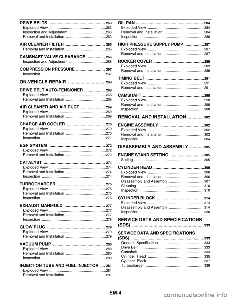
EM-4
DRIVE BELTS ..................................................263
Exploded View .......................................................263
Inspection and Adjustment ....................................263
Removal and Installation .......................................263
AIR CLEANER FILTER ...................................265
Removal and Installation .......................................265
CAMSHAFT VALVE CLEARANCE .................266
Inspection and Adjustment ....................................266
COMPRESSION PRESSURE ..........................267
Inspection ..............................................................267
ON-VEHICLE REPAIR ...............................268
DRIVE BELT AUTO-TENSIONER ...................268
Exploded View .......................................................268
Removal and Installation .......................................268
AIR CLEANER AND AIR DUCT ......................269
Exploded View .......................................................269
Removal and Installation .......................................269
CHARGE AIR COOLER ..................................270
Exploded View .......................................................270
Removal and Installation .......................................270
Inspection ..............................................................271
EGR SYSTEM ..................................................272
Exploded View .......................................................272
Removal and Installation .......................................272
CATALYST ......................................................274
Exploded View .......................................................274
Removal and Installation .......................................274
Inspection ..............................................................274
TURBOCHARGER ..........................................275
Exploded View .......................................................275
Removal and Installation .......................................275
Inspection ..............................................................276
EXHAUST MANIFOLD ....................................277
Exploded View .......................................................277
Removal and Installation .......................................277
Inspection ..............................................................278
GLOW PLUG ...................................................279
Exploded View .......................................................279
Removal and Installation .......................................279
VACUUM PUMP ..............................................280
Exploded View .......................................................280
Removal and Installation .......................................280
Inspection ..............................................................280
INJECTION TUBE AND FUEL INJECTOR .....281
Exploded View .......................................................281
Removal and Installation .......................................281
OIL PAN ............................................................284
Exploded View ......................................................284
Removal and Installation .......................................284
Inspection ..............................................................286
HIGH PRESSURE SUPPLY PUMP ..................287
Exploded View ......................................................287
Removal and Installation .......................................287
ROCKER COVER .............................................289
Exploded View ......................................................289
Removal and Installation .......................................289
TIMING BELT ...................................................291
Exploded View ......................................................291
Removal and Installation .......................................291
CAMSHAFT ......................................................298
Exploded View ......................................................298
Removal and Installation .......................................298
Inspection ..............................................................300
REMOVAL AND INSTALLATION .............302
ENGINE ASSEMBLY .......................................302
Exploded View ......................................................302
Removal and Installation .......................................302
Inspection ..............................................................304
DISASSEMBLY AND ASSEMBLY ...........305
ENGINE STAND SETTING ..............................305
Setting ...................................................................305
CYLINDER HEAD .............................................306
Exploded View ......................................................306
Removal and Installation .......................................306
Disassembly and Assembly ..................................307
Cleaning ................................................................310
Inspection ..............................................................310
CYLINDER BLOCK ..........................................314
Exploded View ......................................................314
Disassembly and Assembly ..................................314
Inspection ..............................................................330
SERVICE DATA AND SPECIFICATIONS
(SDS) .........................................................
333
SERVICE DATA AND SPECIFICATIONS
(SDS) ................................................................
333
General Specification ...........................................333
Drive Belt ..............................................................333
Camshaft ...............................................................333
Cylinder Head ......................................................335
Cylinder Block ......................................................337
Turbocharger ........................................................339
Page 2653 of 5883
![NISSAN TIIDA 2007 Service Repair Manual EM-6
< SYMPTOM DIAGNOSIS >[HR16DE]
NOISE, VIBRATION AND HARSHNESS (NVH) TROUBLESHOOTING
Use the Chart Below to Help You Find the Cause of the Symptom
INFOID:0000000001381372
1. Locate the area where n NISSAN TIIDA 2007 Service Repair Manual EM-6
< SYMPTOM DIAGNOSIS >[HR16DE]
NOISE, VIBRATION AND HARSHNESS (NVH) TROUBLESHOOTING
Use the Chart Below to Help You Find the Cause of the Symptom
INFOID:0000000001381372
1. Locate the area where n](/manual-img/5/57395/w960_57395-2652.png)
EM-6
< SYMPTOM DIAGNOSIS >[HR16DE]
NOISE, VIBRATION AND HARSHNESS (NVH) TROUBLESHOOTING
Use the Chart Below to Help You Find the Cause of the Symptom
INFOID:0000000001381372
1. Locate the area where noise occurs.
2. Confirm the type of noise.
3. Specify the operating condition of engine.
4. Check specified noise source.
If necessary, repair or replace these parts.
A: Closely related B: Related C: Sometimes related —: Not relatedLocation
of noiseTyp e of
noiseOperating condition of engine
Source of
noiseCheck itemRefer-
ence page Before
warm-
upAfter
warm-
upWhen
start-
ingWhen
idlingWhen
racingWhile
driving
Top of en-
gine
Rocker
cover
Cylinder
headTicking or
clickingCA—AB—Tappet
noiseValve clearanceEM-21
Rattle C A — A B CCamshaft
bearing
noiseCamshaft journal oil
clearance
Camshaft runoutEM-123EM-123
Crank-
shaft pul-
ley
Cylinder
block
(Side of
engine)
Oil panSlap or
knock—A—BB—Piston pin
noisePiston to piston pin oil
clearance
Connecting rod small
end clearanceEM-127
EM-130
Slap or
rapA——BBAPiston
slap noisePiston to cylinder bore
clearance
Piston ring side clear-
ance
Piston ring end gap
Connecting rod bend
and torsionEM-127EM-127
EM-127
EM-130
Knock A B C B B BConnect-
ing rod
bearing
noiseConnecting rod small
end clearance
Connecting rod bearing
oil clearanceEM-127EM-130
Knock A B — A B CMain bear-
ing noiseMain bearing oil clear-
ance
Crankshaft runoutEM-131EM-127
Front of
engine
Front cov-
erTapping or
tickingAA—BBBTiming
chain and
chain ten-
sioner
noiseTiming chain cracks
and wear
Timing chain tensioner
operationEM-57
Front of
engineSqueak-
ing or fizz-
ingAB—B—CDrive belt
(Sticking
or slip-
ping)Drive belt deflection
EM-122
Creaking A B A B A BDrive belt
(Slipping)Idler pulley bearing op-
eration
Squall
CreakAB—BABWater
pump
noiseWater pump operationCO-21
Page 2655 of 5883
![NISSAN TIIDA 2007 Service Repair Manual EM-8
< PRECAUTION >[HR16DE]
PRECAUTIONS
3. Disconnect both battery cables. The steering lock will remain released and the steering wheel can be
rotated.
4. Perform the necessary repair operation.
5. W NISSAN TIIDA 2007 Service Repair Manual EM-8
< PRECAUTION >[HR16DE]
PRECAUTIONS
3. Disconnect both battery cables. The steering lock will remain released and the steering wheel can be
rotated.
4. Perform the necessary repair operation.
5. W](/manual-img/5/57395/w960_57395-2654.png)
EM-8
< PRECAUTION >[HR16DE]
PRECAUTIONS
3. Disconnect both battery cables. The steering lock will remain released and the steering wheel can be
rotated.
4. Perform the necessary repair operation.
5. When the repair work is completed, return the ignition switch to the ″LOCK″ position before connecting
the battery cables. (At this time, the steering lock mechanism will engage.)
6. Perform a self-diagnosis check of all control units using CONSULT-II.
Precaution for Drain CoolantINFOID:0000000001527635
Drain coolant when engine is cooled.
Precaution for Disconnecting Fuel PipingINFOID:0000000001527636
Before starting work, make sure no fire or spark producing items are in the work area.
Release fuel pressure before disassembly.
After disconnecting pipes, plug openings to stop fuel leakage.
Precaution for Removal and DisassemblyINFOID:0000000001527637
When instructed to use special service tools, use the specified tools. Always be careful to work safely, avoid
forceful or uninstructed operations.
Exercise maximum care to avoid damage to mating or sliding surfaces.
Cover openings of engine system with tape or the equivalent, if necessary, to seal out foreign materials.
Mark and arrange disassembly parts in an organized way for easy troubleshooting and assembly.
When loosening nuts and bolts, as a basic rule, start with the one furthest outside, then the one diagonally
opposite, and so on. If the order of loosening is specified, do exactly as specified. Power tools may be used
where noted in the step.
Precaution for Inspection, Repair and ReplacementINFOID:0000000001527638
Before repairing or replacing, thoroughly inspect parts. Inspect new replacement parts in the same way, and
replace if necessary.
Precaution for Assembly and InstallationINFOID:0000000001527639
Use torque wrench to tighten bolts or nuts to specification.
When tightening nuts and bolts, as a basic rule, equally tighten in several different steps starting with the
ones in center, then ones on inside and outside diagonally in this order. If the order of tightening is specified,
do exactly as specified.
Replace with new gasket, packing, oil seal or O-ring.
Thoroughly wash, clean, and air-blow each part. Carefully check oil or coolant passages for any restriction
and blockage.
Avoid damaging sliding or mating surfaces. Completely remove foreign materials such as cloth lint or dust.
Before assembly, oil sliding surfaces well.
Release air within route after draining coolant.
Before starting engine, apply fuel pressure to fuel lines with turning ignition switch ON (with engine stopped).
Then make sure that there are no leaks at fuel line connections.
After repairing, start engine and increase engine speed to check coolant, fuel, oil, and exhaust systems for
leakage.
Parts Requiring Angular TighteningINFOID:0000000001527640
Use an angle wrench for the final tightening of the following engine parts:
- Cylinder head bolts
- Camshaft sprocket (INT)
- Main bearing cap bolts
- Connecting rod cap nuts
- Crankshaft pulley bolt (No angle wrench is required as the bolt flange is provided with notches for angular
tightening)
Do not use a torque value for final tightening. Tool number : KV10112100 (BT-8653-A)