Page 4818 of 5883

B1113 – B1115 SATELLITE SENSOR RH
SRC-49
< COMPONENT DIAGNOSIS >
C
D
E
F
G
I
J
K
L
MA
B
SRC
N
O
P
1.IGNITION SWITCH
Turn ignition switch ON.
>> GO TO 2
2.IGNITION SWITCH
After air bag warning lamp lights for 7 seconds, turn ignition switch OFF within 1 second.
>> GO TO 3
3.WAIT TIME
Wait more than 3 seconds.
>> GO TO 4
4.REPEAT STEPS
Repeat steps 1 to 3 twice.
>> GO TO 5
5.IGNITION SWITCH
Turn ignition switch ON.
>> GO TO 6
6.DIAGNOSTIC MODE
SRS system is now in diagnostic mode and AIR BAG warning lamp flashes. Refer to SRC-13, "
Trouble Diag-
nosis without CONSULT-III".
>>END
Diagnosis Procedure (Component diagnosis)INFOID:0000000001396397
Recheck SRS after each replacement.
1.HARNESS CONNECTOR
Is there any visible damage to the connector?
YES or NO
YES >> Replace the harness.
NO >> GO TO 2
2.WIRING HARNESS
Is there any visible damage to the harness?
YES or NO
YES >> Replace the harness.
NO >> GO TO 3
3.RH SIDE AIR BAG SATELLITE SENSOR
Replace the RH side air bag satellite sensor. Refer to SR-12, "
Removal and Installation".
>> GO TO 4
4.AIR BAG DIAGNOSIS SENSOR UNIT
Replace the air bag diagnosis sensor unit. Refer to SR-15, "
Removal and Installation".
Page 4819 of 5883
SRC-50
< COMPONENT DIAGNOSIS >
B1113 – B1115 SATELLITE SENSOR RH
>> GO TO 5
5.RELATED HARNESS
Replace the related harness.
>>END
Page 4820 of 5883

B1XXX AIR BAG DIAGNOSIS SENSOR UNIT
SRC-51
< COMPONENT DIAGNOSIS >
C
D
E
F
G
I
J
K
L
MA
B
SRC
N
O
P
B1XXX AIR BAG DIAGNOSIS SENSOR UNIT
DescriptionINFOID:0000000001396398
DTC B1XXX AIR BAG DIAGNOSIS SENSOR UNIT
The air bag diagnosis sensor unit will run self diagnostics when the ignition switch is turned ON. It has the
potential to set many diagnostic trouble codes which will conform to the B1XXX format, but will not match any
other SRS diagnostic trouble codes. Refer to SRC-76, "
Trouble Diagnosis with CONSULT-III".
PA R T L O C AT I O N
Refer to SRC-7, "SRS Component Parts Location".
DTC LogicINFOID:0000000001396399
DTC DETECTION LOGIC
With CONSULT-lll
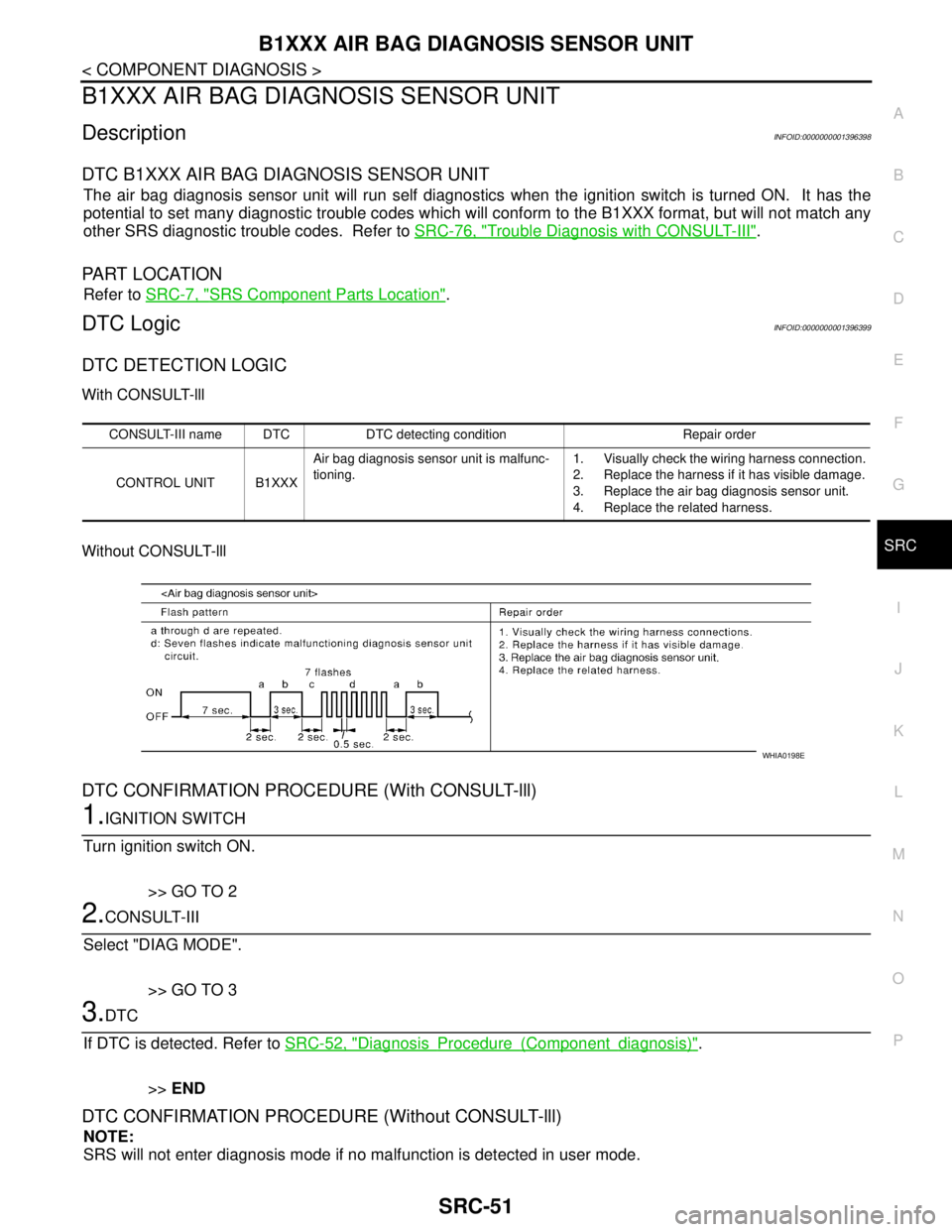
Without CONSULT-lll
DTC CONFIRMATION PROCEDURE (With CONSULT-lll)
1.IGNITION SWITCH
Turn ignition switch ON.
>> GO TO 2
2.CONSULT-III
Select "DIAG MODE".
>> GO TO 3
3.DTC
If DTC is detected. Refer to SRC-52, "
DiagnosisProcedure(Componentdiagnosis)".
>>END
DTC CONFIRMATION PROCEDURE (Without CONSULT-lll)
NOTE:
SRS will not enter diagnosis mode if no malfunction is detected in user mode.
CONSULT-III name DTC DTC detecting condition Repair order
CONTROL UNIT B1XXXAir bag diagnosis sensor unit is malfunc-
tioning.1. Visually check the wiring harness connection.
2. Replace the harness if it has visible damage.
3. Replace the air bag diagnosis sensor unit.
4. Replace the related harness.
WHIA0198E
Page 4821 of 5883

SRC-52
< COMPONENT DIAGNOSIS >
B1XXX AIR BAG DIAGNOSIS SENSOR UNIT
1.IGNITION SWITCH
Turn ignition switch ON.
>> GO TO 2
2.IGNITION SWITCH
After air bag warning lamp lights for 7 seconds, turn ignition switch OFF within 1 second.
>> GO TO 3
3.WAIT TIME
Wait more than 3 seconds.
>> GO TO 4
4.REPEAT STEPS
Repeat steps 1 to 3 twice.
>> GO TO 5
5.IGNITION SWITCH
Turn ignition switch ON.
>> GO TO 6
6.DIAGNOSTIC MODE
SRS system is now in diagnostic mode and AIR BAG warning lamp flashes. Refer to SRC-13, "
Trouble Diag-
nosis without CONSULT-III".
>>END
Diagnosis Procedure (Component diagnosis)INFOID:0000000001396400
Recheck SRS after each replacement.
1.HARNESS CONNECTOR
Is there any visible damage to the connector?
YES or NO
YES >> Replace the harness.
NO >> GO TO 2
2.WIRING HARNESS
Is there any visible damage to the harness?
YES or NO
YES >> Replace the harness.
NO >> GO TO 3
3.AIR BAG DIAGNOSIS SENSOR UNIT
Replace the air bag diagnosis sensor unit. Refer to SR-15, "
Removal and Installation".
>> GO TO 4
4.RELATED HARNESS
Replace the related harness.
Page 4822 of 5883
B1XXX AIR BAG DIAGNOSIS SENSOR UNIT
SRC-53
< COMPONENT DIAGNOSIS >
C
D
E
F
G
I
J
K
L
MA
B
SRC
N
O
P
>>END
Page 4823 of 5883

SRC-54
< COMPONENT DIAGNOSIS >
B1209 – B1210 COLLISION DETECTION
B1209 – B1210 COLLISION DETECTION
DescriptionINFOID:0000000001396407
DTC B1209 - B1210 COLLISION DETECTION
The air bag diagnosis sensor unit will set this DTC if it has detected a collision which has resulted in a frontal
or side deployment of one or more air bags or pre-tensioners. If this DTC is detected after a SRS repair, the
air bag diagnosis sensor unit has not yet been replaced. This DTC can not be erased.
PA R T L O C AT I O N
Refer to SRC-7, "SRS Component Parts Location".
DTC LogicINFOID:0000000001396408
DTC DETECTION LOGIC
With CONSULT-lll
DTC CONFIRMATION PROCEDURE (With CONSULT-lll)
1.IGNITION SWITCH
Turn ignition switch ON.
>> GO TO 2
2.CONSULT-III
Select "DIAG MODE".
>> GO TO 3
3.DTC
If DTC is detected. Refer to SRC-54, "
DiagnosisProcedure(Componentdiagnosis)".
>>END
Diagnosis Procedure (Component diagnosis)INFOID:0000000001396409
Refer to SR-23, "For Frontal Collision" or SR-24, "For Side and Rollover Collision".
CONSULT-III name DTC DTC detecting condition Repair order
FRONTAL COLLISION
DETECTIONB1209Driver and/or front passenger air bag mod-
ules are deployed.Refer to SR-23, "
For Frontal Collision".
SIDE COLLISION DE-
TECTIONB1210Side and/or curtain air bag modules are
deployed.Refer to SR-24, "
For Side and Rollover Collision".
Page 4827 of 5883
SRC-58
< ECU DIAGNOSIS >
DIAGNOSIS SENSOR UNIT
ECU DIAGNOSIS
DIAGNOSIS SENSOR UNIT
Reference ValueINFOID:0000000001726678
SEAT BELT WARNING LAMP CONTROL UNIT HARNESS TERMINAL LAYOUT
TERMINALS AND REFERENCE VALUES FOR SEAT BELT WARNING LAMP CONTROL UNIT
AWHIA0027ZZ
Te r m i n a l
(color)ItemCondition
Reference value (V)
(Approx.) Ignition
switchOperation
1 (V) Battery power — — Battery voltage
8 (O)Driver seat belt warn-
ing lamp outputON — 0
15 (BR)Passenger seat belt
warning lamp outputON — 0
16 (BR) Ground — — —
17 (O) Ignition power ON — Battery voltage
21 (O)Driver seat belt buck-
le switch inputON Driver seat belt fastened 12
22 (LG)Passenger seat belt
buckle switch inputON Passenger seat belt fastened 12
36 (V)Vehicle speed signal
(2-pulse)ONSpeedometer operated
[When vehicle speed is approx. 40 km/h (25
MPH)] NOTE:
Maximum voltage may be 5V due to
specifications (connected units).
PKIC0642E
Page 4828 of 5883
DIAGNOSIS SENSOR UNIT
SRC-59
< ECU DIAGNOSIS >
C
D
E
F
G
I
J
K
L
MA
B
SRC
N
O
P
Wiring Diagram — RHD Models —INFOID:0000000001396410
ALHWA0008GB