Page 722 of 2896

BODY REPAIR
BL-233
C
D
E
F
G
H
J
K
L
MA
B
BL
Revision: June 20062007 Versa
1. Upper dash assembly
2. Lower dash assembly
3. Lower dash crossmember
4. Front pillar inner reinforcement (RH&LH)
5. Lower dash reinforcement
6. 4th crossmember (RH&LH)
7. Front side member rear extension (RH&LH)
8. 3rd crossmember (RH&LH)
9. Front seat outer rear bracket (RH&LH)
10. Front seat inner rear bracket (RH&LH)
11. 2nd crossmember (RH&LH)
12. Front seat outer front bracket (RH&LH)
13. Front seat inner front bracket (RH&LH)
14. Fender bracket (RH&LH)
15. Strut housing assembly RH
16. Cowl top side upper (RH&LH)
17. Front strut housing (RH&LH)
18. Upper torque rod reinforcement
19. Closing plate assembly RH
20. Engine mount reinforcement
21. Strut tower front reinforcement RH
22. Front hoodledge lower RH
23. Frame bracket outer (RH&LH)
24. Front bumper support bracket (RH&LH)
25. Closing plate (RH&LH)
26. Front suspension rear bracket (RH&LH)
27. Front side member outrigger (RH&LH)
28. Front side member assembly (RH&LH)
29. Front side member (RH&LH)
30. Frame bracket (RH&LH)
31. Closing plate assembly LH
32. Hoodledge connector (RH&LH)
33. Radiator core side support (RH&LH)
34. Radiator core support upper (RH&LH)
35. Hoodledge upper (RH&LH)
36. Hoodledge reinforcement assembly (RH&LH)
37. Dash side (RH&LH)
38. Dash side assembly (RH& LH)
39. Front floor reinforcement (RH&LH)
40. Front floor front (RH&LH)
41. Front floor center
42. Rear seat crossmember
43. Rear center crossmember
44. Rear seat upper crossmember
45. Rear side member (RH&LH)
46. Sill inner extension (RH&LH)
47. Rear side member extension (RH&LH)
48. Rear side member assembly (RH & LH)
49. Rear floor front
Page 2015 of 2896

GI-44
TOW TRUCK TOWING
Revision: June 20062007 Versa
TOW TRUCK TOWINGPFP:00000
To w Tr u c k To w i n gEAS00201
CAUTION:
�All applicable local laws regarding the towing operation must be obeyed.
�It is necessary to use proper towing equipment to avoid possible damage to the vehicle during
towing operation. Towing is in accordance with Towing Procedure Manual at dealer.
�Always attach safety chains before towing.
�When towing, make sure that the transmission, steering system and power train are in good order.
If any unit is damaged, dollies must be used.
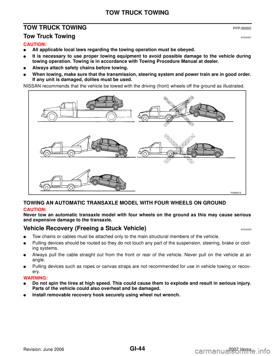
NISSAN recommends that the vehicle be towed with the driving (front) wheels off the ground as illustrated.
TOWING AN AUTOMATIC TRANSAXLE MODEL WITH FOUR WHEELS ON GROUND
CAUTION:
Never tow an automatic transaxle model with four wheels on the ground as this may cause serious
and expensive damage to the transaxle.
Vehicle Recovery (Freeing a Stuck Vehicle)EAS00202
�Tow chains or cables must be attached only to the main structural members of the vehicle.
�Pulling devices should be routed so they do not touch any part of the suspension, steering, brake or cool-
ing systems.
�Always pull the cable straight out from the front or rear of the vehicle. Never pull on the vehicle at an
angle.
�Pulling devices such as ropes or canvas straps are not recommended for use in vehicle towing or recov-
ery.
WAR NIN G:
�Do not spin the tires at high speed. This could cause them to explode and result in serious injury.
Parts of the vehicle could also overheat and be damaged.
�Install removable recovery hook securely using wheel nut wrench.
PIIB6801E
Page 2606 of 2896

PS-12
POWER STEERING GEAR
Revision: June 20062007 Versa
POWER STEERING GEARPFP:49001
Removal and InstallationEGS0014Y
COMPONENT
CAUTION:
Spiral cable may be cut if steering wheel turns while separating steering column assembly and steer-
ing gear assembly. Be sure to secure steering wheel using string to avoid turning.
REMOVAL
1. Set vehicle to the straight-ahead position.
2. Remove bolt of intermediate shaft (lower side), and then remove intermediate shaft from steering gear
pinion shaft.
3. Raise vehicle.
4. Remove tires from vehicle with a power tool.
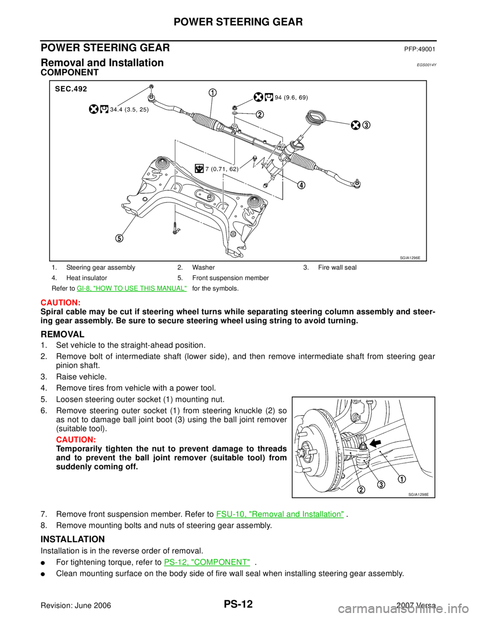
5. Loosen steering outer socket (1) mounting nut.
6. Remove steering outer socket (1) from steering knuckle (2) so
as not to damage ball joint boot (3) using the ball joint remover
(suitable tool).
CAUTION:
Temporarily tighten the nut to prevent damage to threads
and to prevent the ball joint remover (suitable tool) from
suddenly coming off.
7. Remove front suspension member. Refer to FSU-10, "
Removal and Installation" .
8. Remove mounting bolts and nuts of steering gear assembly.
INSTALLATION
Installation is in the reverse order of removal.
�For tightening torque, refer to PS-12, "COMPONENT" .
�Clean mounting surface on the body side of fire wall seal when installing steering gear assembly.
1. Steering gear assembly 2. Washer 3. Fire wall seal
4. Heat insulator 5. Front suspension member
Refer to GI-8, "
HOW TO USE THIS MANUAL" for the symbols.
SGIA1296E
SGIA1298E