Page 1712 of 2896

DTC P2A00 A/F SENSOR 1
EC-543
C
D
E
F
G
H
I
J
K
L
MA
EC
Revision: June 20062007 Versa
Specification data are reference values and are measured between each terminal and ground.
Pulse signal is measured by CONSULT-II.
CAUTION:
Do not use ECM ground terminals when measuring input/output voltage. Doing so may result in dam-
age to the ECM's transistor. Use a ground other than ECM terminals, such as the ground.
: Average voltage for pulse signal (Actual pulse signal can be confirmed by oscilloscope.)
Diagnostic ProcedureUBS00QNU
1. CHECK GROUND CONNECTIONS
1. Turn ignition switch OFF.
2. Loosen and retighten ground screws on the body.
Refer to EC-150, "
Ground Inspection" .
OK or NG
OK >> GO TO 2.
NG >> Repair or replace ground connections.
TERMI-
NAL
NO.WIRE
COLORITEM CONDITION DATA (DC Voltage)
3 G A/F sensor 1 heater[Engine is running]
�Warm-up condition
�Idle speed
(More than 140 seconds after starting
engine)Approximately 2.9 - 8.8V
49 W A/F sensor 1[Engine is running]
�Warm-up condition
�Engine speed: 2,000 rpmApproximately 1.8V
Output voltage varies with air fuel
ratio.
53 B A/F sensor 1[Ignition switch: ON]Approximately 2.2V
PBIA8148J
:Vehicle front
1. Body ground E24 2. Engine ground F9 3. Engine ground F16
4. Body ground E15
BBIA0698E
Page 1713 of 2896
EC-544Revision: June 2006
DTC P2A00 A/F SENSOR 1
2007 Versa
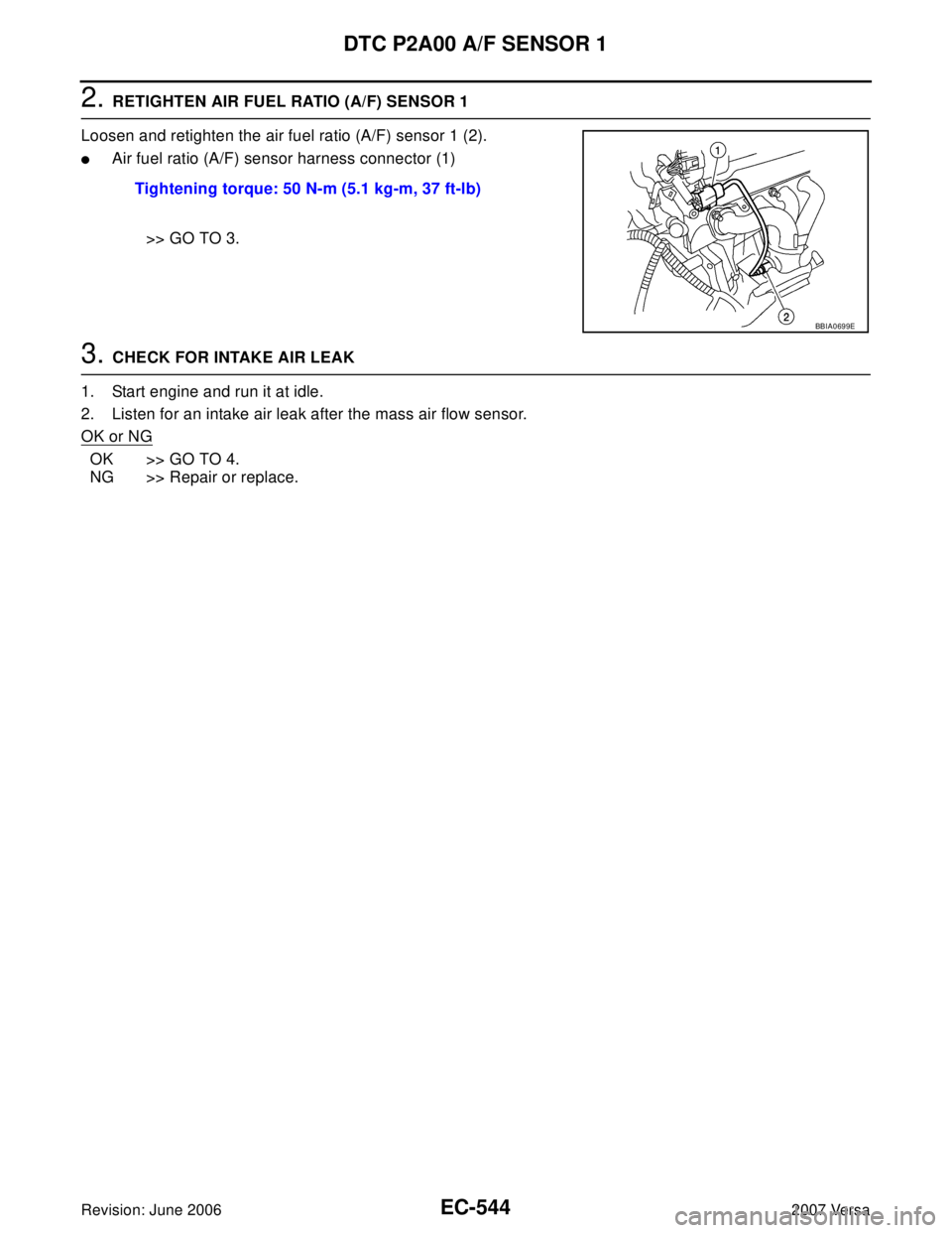
2. RETIGHTEN AIR FUEL RATIO (A/F) SENSOR 1
Loosen and retighten the air fuel ratio (A/F) sensor 1 (2).
�Air fuel ratio (A/F) sensor harness connector (1)
>> GO TO 3.
3. CHECK FOR INTAKE AIR LEAK
1. Start engine and run it at idle.
2. Listen for an intake air leak after the mass air flow sensor.
OK or NG
OK >> GO TO 4.
NG >> Repair or replace.Tightening torque: 50 N-m (5.1 kg-m, 37 ft-lb)
BBIA0699E
Page 1714 of 2896

DTC P2A00 A/F SENSOR 1
EC-545
C
D
E
F
G
H
I
J
K
L
MA
EC
Revision: June 20062007 Versa
4. CLEAR THE SELF-LEARNING DATA.
With CONSULT-II
1. Start engine and warm it up to normal operating temperature.
2. Select “SELF-LEARNING CONT” in “WORK SUPPORT” mode with CONSULT-II.
3. Clear the self-learning control coefficient by touching “CLEAR”.
4. Run engine for at least 10 minutes at idle speed.
Is the 1st trip DTC P0171 and P0172 detected?
Is it difficult to start engine?
Without CONSULT-II
1. Start engine and warm it up to normal operating temperature.
2. Turn ignition switch OFF.
3. Disconnect mass air flow sensor (1) harness connector.
4. Restart engine and let it idle for at least 5 seconds.
5. Stop engine and reconnect mass air flow sensor harness con-
nector.
6. Make sure DTC P0102 is displayed.
7. Erase the DTC memory. Refer to EC-60, "
HOW TO ERASE
EMISSION-RELATED DIAGNOSTIC INFORMATION" .
8. Make sure DTC P0000 is displayed.
9. Run engine for at least 10 minutes at idle speed.
Is the 1st trip DTC P0171 and P0172 detected?
Is it difficult to start engine?
Ye s o r N o
Yes >> Perform trouble diagnosis for DTC P0171 or P0172. Refer to EC-276, "DTC P0171 FUEL INJEC-
TION SYSTEM FUNCTION" or EC-284, "DTC P0172 FUEL INJECTION SYSTEM FUNCTION" .
No >> GO TO 5.
5. CHECK HARNESS CONNECTOR
1. Turn ignition switch OFF.
2. Disconnect A/F sensor 1 harness connector (1).
–Air fuel ratio (A/F) sensor (2)
3. Check harness connector for water.
OK or NG
OK >> GO TO 6.
NG >> Repair or replace harness connector.
PBIB2035E
BBIA0701E
Water should no exist.
BBIA0699E
Page 1717 of 2896

EC-548Revision: June 2006
DTC P2A00 A/F SENSOR 1
2007 Versa
13. CLEAR A/F ADJUSTMENT DATA
With CONSULT-II
1. Start engine and warm it up to normal operating temperature.
2. Select “SELF-LEARNING CONT” in “WORK SUPPORT” mode with CONSULT-II.
3. Clear the self-learning control coefficient by touching “CLEAR”.
Without CONSULT-II
1. Start engine and warm it up to normal operating temperature.
2. Turn ignition switch OFF.
3. Disconnect mass air flow sensor harness (1) connector.
4. Restart engine and let it idle for at least 5 seconds.
5. Stop engine and reconnect mass air flow sensor harness con-
nector.
6. Make sure DTC P0102 is displayed.
7. Erase the DTC memory. Refer to EC-60, "
HOW TO ERASE
EMISSION-RELATED DIAGNOSTIC INFORMATION" .
8. Make sure DTC P0000 is displayed.
>> GO TO 14.
14. CONFIRM A/F ADJUSTMENT DATA
1. Turn ignition switch OFF and then ON.
2. Select “A/F ADJ-B1” in “DATA MONITOR” mode with CON-
SULT-II.
3. Make sure that “0.000” is displayed on CONSULT-II screen.
>>INSPECTION END
Removal and InstallationUBS00QNV
AIR FUEL RATIO SENSOR
Refer to EM-21, "EXHAUST MANIFOLD" .
PBIB2035E
BBIA0701E
PBIB3201E
Page 1733 of 2896
EC-564Revision: June 2006
FUEL INJECTOR
2007 Versa
FUEL INJECTORPFP:16600
Component DescriptionUBS00PTO
The fuel injector is a small, precise solenoid valve. When the ECM
supplies a ground to the fuel injector circuit, the coil in the fuel injec-
tor is energized. The energized coil pulls the ball valve back and
allows fuel to flow through the fuel injector into the intake manifold.
The amount of fuel injected depends upon the injection pulse dura-
tion. Pulse duration is the length of time the fuel injector remains
open. The ECM controls the injection pulse duration based on
engine fuel needs.
CONSULT-II Reference Value in Data Monitor ModeUBS00PTP
Specification data are reference values.
PBIA9664J
MONITOR ITEM CONDITION SPECIFICATION
B/FUEL SCHDL See EC-133, "
TROUBLE DIAGNOSIS - SPECIFICATION VALUE" .
INJ PULSE-B1
�Engine: After warming up
�Air conditioner switch: OFF
�Shift lever: P or N (A/T, CVT),
Neutral (M/T)
�No loadIdle 2.0 - 3.0 msec
2,000 rpm 1.9 - 2.9 msec
Page 1735 of 2896

EC-566Revision: June 2006
FUEL INJECTOR
2007 Versa
Specification data are reference values and are measured between each terminal and ground.
Pulse signal is measured by CONSULT-II.
CAUTION:
Do not use ECM ground terminals when measuring input/output voltage. Doing so may result in dam-
age to the ECM's transistor. Use a ground other than ECM terminals, such as the ground.
: Average voltage for pulse signal (Actual pulse signal can be confirmed by oscilloscope.)
Diagnostic ProcedureUBS00PTR
1. INSPECTION START
Turn ignition switch to START.
Is any cylinder ignited?
Ye s o r N o
Yes >> GO TO 2.
No >> GO TO 3.
TERMI-
NAL
NO.WIRE
COLORITEM CONDITION DATA (DC Voltage)
25
29
30
31V
Y
O
LFuel injector No. 4
Fuel injector No. 3
Fuel injector No. 2
Fuel injector No. 1[Engine is running]
�Warm-up condition
�Idle speed
NOTE:
The pulse cycle changes depending on rpm
at idleBATTERY VOLTAGE
(11 - 14V)
[Engine is running]
�Warm-up condition
�Engine speed: 2,000 rpmBATTERY VOLTAGE
(11 - 14V)
PBIB0529E
PBIA4943J
Page 1736 of 2896
FUEL INJECTOR
EC-567
C
D
E
F
G
H
I
J
K
L
MA
EC
Revision: June 20062007 Versa
2. CHECK OVERALL FUNCTION
With CONSULT-II
1. Start engine.
2. Perform “POWER BALANCE” in “ACTIVE TEST” mode with
CONSULT-II.
3. Make sure that each circuit produces a momentary engine
speed drop.
Without CONSULT-II
1. Start engine.
2. Listen to each fuel injector operating sound.
OK or NG
OK >>INSPECTION END
NG >> GO TO 3.
PBIB0133E
Clicking noise should be heard.
PBIB3332E
Page 1739 of 2896

EC-570Revision: June 2006
FUEL PUMP
2007 Versa
FUEL PUMPPFP:17042
DescriptionUBS00PTU
SYSTEM DESCRIPTION
*: ECM determines the start signal status by the signals of engine speed and battery voltage.
The ECM activates the fuel pump for several seconds after the ignition switch is turned ON to improve engine
startability. If the ECM receives a engine speed signal from the crankshaft position sensor (POS) and cam-
shaft position sensor (PHASE), it knows that the engine is rotating, and causes the pump to operate. If the
engine speed signal is not received when the ignition switch is ON, the engine stalls. The ECM stops pump
operation and prevents battery discharging, thereby improving safety. The ECM does not directly drive the fuel
pump. It controls the ON/OFF fuel pump relay, which in turn controls the fuel pump.
COMPONENT DESCRIPTION
A turbine type design fuel pump is used in the fuel tank.
�Fuel level sensor unit and fuel pump (1)
�Fuel pressure regulator (2)
�Fuel level sensor (3)
�Fuel tank temperature sensor (4)
CONSULT-II Reference Value in Data Monitor ModeUBS00PTV
Specification data are reference values.
Sensor Input Signal to ECM ECM Function Actuator
Crankshaft position sensor (POS)
Camshaft position sensor (PHASE)Engine speed*
Fuel pump control Fuel pump relay
Battery Battery voltage*
Condition Fuel pump operation
Ignition switch is turned to ON Operates for 1 second
Engine running and crankingOperates
Engine: StoppedStops in 1.5 seconds
Except as shown aboveSto ps
BBIA0704E
MONITOR ITEM CONDITION SPECIFICATION
FUEL PUMP RLY
�For 1 second after turning ignition switch ON
�Engine running or crankingON
�Except above conditions OFF