Page 1825 of 2896
.
2. Remove the")
EM-16Revision: June 2006
AIR CLEANER AND AIR DUCT
2007 Versa
AIR CLEANER AND AIR DUCTPFP:16500
ComponentsEBS00T5V
Removal and InstallationEBS00T5W
REMOVAL
1. Remove the air duct (inlet).
2. Remove the air cleaner filter from the air cleaner case. Refer to EM-17, "
Changing Air Cleaner Filter" .
3. Remove the air duct [between air duct (inlet) and air cleaner case] from the air cleaner case.
4. Remove the PCV hose.
5. Remove the air duct (between air cleaner case and electric throttle control actuator).
�Add marks as necessary for easier installation.
6. Remove air cleaner case with the following procedure.
a. Remove battery. Refer to SC-4, "
BATTERY" .
b. Disconnect harness connector from mass air flow sensor.
c. Remove the air cleaner case.
7. Remove the mass air flow sensor from the air cleaner case, if necessary.
CAUTION:
�Handle it carefully and avoid impacts.
�Do not touch sensor part.
INSTALLATION
Installation is in the reverse order of removal.
1. Air cleaner filter 2. Mass air flow sensor 3. O-ring
4. Holder 5. Air cleaner cover 6. Air duct
7. PCV hose 8. Clip 9. Air duct (Inlet)
10. Resonator 11. Air duct 12. Grommet
13. Air cleaner case A. To electric throttle control actuator B. To rocker cover
WBIA0770E
Page 1830 of 2896
EXHAUST MANIFOLD
EM-21
C
D
E
F
G
H
I
J
K
L
MA
EM
Revision: June 20062007 Versa
EXHAUST MANIFOLDPFP:14004
ComponentsEBS00U7E
Removal and InstallationEBS00U7F
REMOVAL
1. Remove exhaust front tube. Refer to EX-4, "Removal and Installation" .
2. Remove exhaust manifold cover.
3. Remove the A/F sensor 1, using Tool (A).
CAUTION:
Handle it carefully and avoid impacts.
4. Remove exhaust manifold side bolt of exhaust manifold stay.
1. Exhaust manifold cover 2. Exhaust manifold 3. Gasket
4. Stud bolt 5. Bracket 6. A/F ratio sensor 1
7. Exhaust manifold stay Engine front
WBIA0778E
Tool number :KV991J0050 (J-44626)
WBIA0772E
Page 1832 of 2896
EXHAUST MANIFOLD
EM-23
C
D
E
F
G
H
I
J
K
L
MA
EM
Revision: June 20062007 Versa
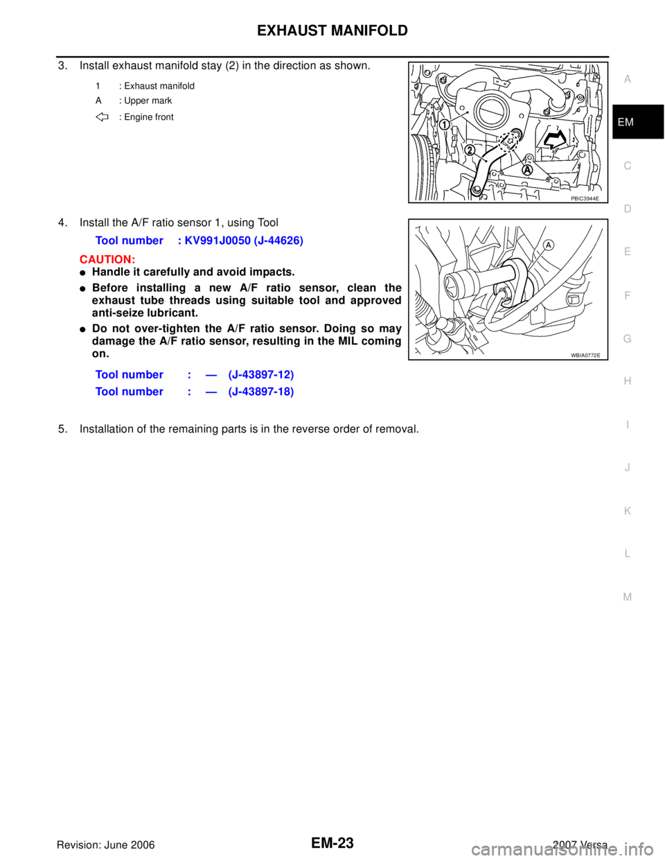
3. Install exhaust manifold stay (2) in the direction as shown.
4. Install the A/F ratio sensor 1, using Tool
CAUTION:
�Handle it carefully and avoid impacts.
�Before installing a new A/F ratio sensor, clean the
exhaust tube threads using suitable tool and approved
anti-seize lubricant.
�Do not over-tighten the A/F ratio sensor. Doing so may
damage the A/F ratio sensor, resulting in the MIL coming
on.
5. Installation of the remaining parts is in the reverse order of removal.
1 : Exhaust manifold
A: Upper mark
: Engine front
PBIC3944E
Tool number : KV991J0050 (J-44626)
Tool number : — (J-43897-12)
Tool number : — (J-43897-18)
WBIA0772E
Page 1856 of 2896

CAMSHAFT
EM-47
C
D
E
F
G
H
I
J
K
L
MA
EM
Revision: June 20062007 Versa
CAMSHAFTPFP:13001
ComponentsEBS00U7O
Removal and InstallationEBS00U7P
REMOVAL
WA RN ING:
�Put a “CAUTION: FLAMMABLE” sign in the workshop.
�Be sure to work in a well ventilated area and furnish workshop with a CO2 fire extinguisher.
�Do not smoke while servicing fuel system. Keep open flames and sparks away from the work area.
1. Release the fuel pressure. Refer to EC-81, "
FUEL PRESSURE RELEASE" .
2. Disconnect negative battery cable. Refer to SC-9, "
Removal and Installation" .
3. Remove front RH wheel. Refer to WT-6, "
ROAD WHEEL TIRE ASSEMBLY" .
4. Remove front fender protector (RH). Refer to EI-22, "
FENDER PROTECTOR" .
5. Drain engine coolant. Refer to CO-8, "
ENGINE COOLANT" .
NOTE:
Perform this step when engine is cold.
6. Remove the following parts.
�Intake manifold; Refer to EM-18, "INTAKE MANIFOLD" .
1. O-ring 2. Camshaft position sensor (PHASE) 3. Camshaft bracket
4. Camshaft sprocket (EXH) 5. Camshaft sprocket (INT) 6. Camshaft (EXH)
7. Camshaft (INT) 8. Valve lifter (EXH) 9. Valve lifter (INT)
10. Cylinder head
A. Refer to EM-51
.
PBIC4589E
Page 1857 of 2896

EM-48Revision: June 2006
CAMSHAFT
2007 Versa
�Rocker cover; Refer toEM-30, "IGNITION COIL, SPARK PLUG AND ROCKER COVER" .
�Fuel tube and fuel injector assembly; Refer to EM-33, "FUEL INJECTOR AND FUEL TUBE" .
�Front cover, timing chain and related parts; Refer to EM-37, "TIMING CHAIN" .
7. Remove camshaft position sensor (PHASE) from camshaft bracket.
CAUTION:
�Handle carefully to avoid dropping and shocks.
�Never disassemble.
�Never allow metal powder to adhere to magnetic part at sensor tip.
�Never place sensor in a location where it is exposed to magnetism.
8. Put the matching mark (A) on the camshaft sprocket (INT) (2)
and the camshaft bracket (1) as shown.
NOTE:
It prevents the knock pin of the camshaft (INT) from engaging
with the incorrect pin hole when installing the camshaft sprocket
(INT).
9. Remove camshaft sprockets (INT) (1) and (EXH) (2).
�Secure hexagonal part (A) of camshaft with a wrench. Loosen
camshaft sprocket bolts and remove camshaft sprocket.
CAUTION:
�Never rotate crankshaft or camshaft while timing chain
is removed. It causes interference between valve and
piston.
�Never loosen the bolts with securing anything other
than the camshaft hexagonal part or with tensioning
the timing chain.
10. Loosen bolts in reverse order as shown.
11. Cut liquid gasket by prying the position ( ) shown, and then
remove the camshaft bracket.
CAUTION:
�Be careful not to damage the mating surface.
�A more adhesive liquid gasket is applied compared to
previous types when shipped, so it should not be forced
off the position not specified.
: Engine front
PBIC3992J
PBIC3454J
: Engine front
PBIC3176J
: Engine front
PBIC3358J
Page 1887 of 2896

EM-78Revision: June 2006
CYLINDER BLOCK
2007 Versa
Disassembly and AssemblyEBS00U7X
DISASSEMBLY
1. Remove engine and transaxle assembly from vehicle, separate transaxle from engine. Refer to EM-73,
"ENGINE ASSEMBLY" .
2. Install engine to engine stand as follows;
a. Remove flywheel (M/T models) or drive plate (1) (A/T or CVT
models).
�Secure flywheel (M/T models) or drive plate (A/T or CVT mod-
els) using Tool (A), and remove bolts.
CAUTION:
Be careful not to damage or scratch drive plate (A/T or CVT
models) and contact surface for clutch disc of flywheel (M/T
models).
NOTE:
Figure shows drive plate (A/T or CVT models)
b. Lift the engine with a hoist to install it onto widely use engine stand.
CAUTION:
�Use the engine stand that has a load capacity [approximately 135 kg (298 lb) or more] large
enough for supporting the engine weight.
�If the load capacity of stand is not adequate, remove the following parts beforehand to reduce the
potential risk of overturning stand.
–Exhaust manifold; Refer to EM-21, "EXHAUST MANIFOLD" .
–Rocker cover; Refer to EM-30, "IGNITION COIL, SPARK PLUG AND ROCKER COVER" .
NOTE:
The figure shows an example of widely used engine stand (A)
that can support mating surface of transaxle with flywheel (M/T
models) or drive plate (A/T or CVT models) removed.
CAUTION:
Before removing the hanging chains, make sure the engine
stand is stable and there is no risk of overturning.
3. Remove oil pan (upper and lower). Refer to EM-24, "
OIL PAN" .
4. Remove cylinder head. Refer to EM-62, "
CYLINDER HEAD" .
5. Remove thermostat housing. Refer to CO-18, "
THERMOSTAT" .
1. Cylinder block 2. O-ring 3. Crankshaft position sensor (POS)
4.Crankshaft position sensor (POS)
cover5.Oil filter (for intake valve timing con-
trol)6. Knock sensor
7. Oil pressure switch 8. Top ring 9. Second ring
10. Oil ring 11. Snap ring 12. Piston
13. Piston pin 14. Connecting rod 15. Thrust bearing
16. Connecting rod bearing upper 17. Main bearing upper 18. Crankshaft key
19. Main bearing lower 20. Connecting rod bearing lower 21. Connecting rod bearing cap
22. Connecting rod bolt 23. Main bearing cap 24. Main bearing cap bolt
25. Crankshaft 26. Pilot converter (A/T or CVT models) 27. Signal plate
28. Rear oil seal 29. Drive plate (A/T or CVT models) 30. Reinforcement plate (A/T or CVT
models)
31. Flywheel (M/T models) 32. Block heater (Canada only) A. Refer to EM-81
Tool number : KV 11105210 (J-44716)
PBIC3226J
PBIC3227J
Page 1888 of 2896
")
CYLINDER BLOCK
EM-79
C
D
E
F
G
H
I
J
K
L
MA
EM
Revision: June 20062007 Versa
6. Remove knock sensor.
CAUTION:
Carefully handle knock sensor avoiding shocks.
7. Remove crankshaft position sensor (POS) cover and crankshaft position sensor (POS).
CAUTION:
�Avoid impacts such as a dropping.
�Never disassemble.
�Keep it away from metal particles.
�Never place sensor in a location where it is exposed to magnetism.
8. Remove oil filter (for intake valve timing control).
9. Remove pilot converter (1) using Tool (A). (A/T or CVT models)
NOTE:
M/T models have no pilot converter.
10. Position crankshaft pin corresponding to connecting rod to be removed onto the bottom dead center.
NOTE:
Before removing piston and connecting rod assembly, check the connecting rod side clearance. Refer to
EM-95, "
CONNECTING ROD SIDE CLEARANCE" .
11. Remove connecting rod cap.
12. Using a suitable tool, push piston and connecting rod assembly
out to the cylinder head side.
CAUTION:
�Be careful not to damage matching surface with connect-
ing rod cap.
�Be careful not to damage the cylinder wall and crankshaft
pin, resulting from an interference of the connecting rod
big end.
13. Remove connecting rod bearings.
CAUTION:
When removing them, note the installation position. Keep them in the correct order.
14. Remove piston rings form piston.
�Before removing piston rings, check the piston ring side clearance. Refer to EM-96, "PISTON RING
SIDE CLEARANCE" . Tool number :ST16610001 (J-23907)
PBIC3229J
PBIC0259E
Page 1895 of 2896
 or drive plate (1) (A/T or CVT mod-
els).
�Secure crankshaft using Tool. (A), and tighten bolts crosswise
over seve")
EM-86Revision: June 2006
CYLINDER BLOCK
2007 Versa
28. Install flywheel (M/T models) or drive plate (1) (A/T or CVT mod-
els).
�Secure crankshaft using Tool. (A), and tighten bolts crosswise
over several times.
NOTE:
A/T model shown CVT and M/T similar.
�Install pilot converter (1), drive plate (2) and reinforcement
plate (3) as shown (A/T or CVT models).
�Using a suitable tool of 33 mm. (1.30 in) in diameter, press-fit
pilot converter into the end of crankshaft until it stops (A/T or
CVT models).
NOTE:
M/T models have no pilot converter and reinforcement plate.
29. Install knock sensor (1) with connector facing toward the rear of
engine.
CAUTION:
�Never tighten bolts while holding the connector.
�If any impact by dropping is applied to knock sensor,
replace it with a new one.
NOTE:
�Make sure that there is no foreign material on the cylinder
block mating surface and the back surface of knock sensor.
�Make sure that knock sensor does not interfere with other parts.
30. Install crankshaft position sensor (POS) and crankshaft position sensor (POS) cover.
CAUTION:
�Avoid impacts such as a dropping.
�Keep it away from metal particles.
�Never place sensor in a location where it is exposed to magnetism.
31. Install oil filter (for intake valve timing control) (1) in the direction
shown.
�Make sure that the oil filter does not protrude from the upper
surface of cylinder block (2) after installation.
32. Assemble in the reverse order of disassembly.Tool number : KV11105210 (J-44716)
PBIC3998E
A : Crankshaft rear end
B: R
PBIC4075E
A : Cylinder block left side
: Engine front
PBIC3246J
PBIC3260J