Page 439 of 2896
AV-42
AUDIO
Revision: June 20062007 Versa
7. SUBWOOFER SIGNAL CHECK
1. Connect audio unit connector and subwoofer connector.
2. Turn ignition switch to ACC.
3. Check the signal between audio unit harness connector termi-
nals with CONSULT-II or oscilloscope.
OK or NG
OK >> Replace subwoofer. Refer to AV- 4 7 , "SUBWOOFER" .
NG >> Replace audio unit. Refer to AV- 4 3 , "
AUDIO UNIT" .
Te r m i n a l s
Condi-
tionReference
signal (+) (-)
Con-
nec-
torTe r -
minalCon-
nec-
torTe r -
minal
M44 26 M44 24Receive
audio
signal
WKIA5449E
SKIA0177E
Page 440 of 2896

AUDIO
AV-43
C
D
E
F
G
H
I
J
L
MA
B
AV
Revision: June 20062007 Versa
Removal and InstallationEKS00I4G
AUDIO UNIT
Removal
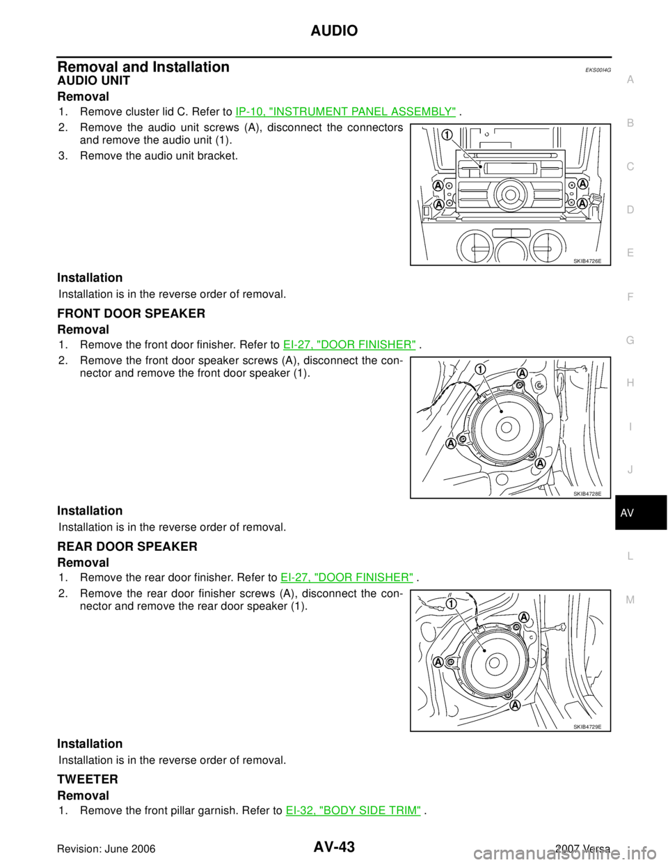
1. Remove cluster lid C. Refer to IP-10, "INSTRUMENT PANEL ASSEMBLY" .
2. Remove the audio unit screws (A), disconnect the connectors
and remove the audio unit (1).
3. Remove the audio unit bracket.
Installation
Installation is in the reverse order of removal.
FRONT DOOR SPEAKER
Removal
1. Remove the front door finisher. Refer to EI-27, "DOOR FINISHER" .
2. Remove the front door speaker screws (A), disconnect the con-
nector and remove the front door speaker (1).
Installation
Installation is in the reverse order of removal.
REAR DOOR SPEAKER
Removal
1. Remove the rear door finisher. Refer to EI-27, "DOOR FINISHER" .
2. Remove the rear door finisher screws (A), disconnect the con-
nector and remove the rear door speaker (1).
Installation
Installation is in the reverse order of removal.
TWEETER
Removal
1. Remove the front pillar garnish. Refer to EI-32, "BODY SIDE TRIM" .
SKIB4726E
SKIB4728E
SKIB4729E
Page 441 of 2896
AV-44
AUDIO
Revision: June 20062007 Versa
2. Remove the tweeter screw (A), disconnect the connector and
remove the tweeter (1).
Installation
Installation is in the reverse order of removal.
SATELLITE TUNER MODULE
Removal
1. Remove the luggage side lower finisher (LH). Refer to EI-42, "LUGGAGE FLOOR TRIM" .
2. Remove the subwoofer. Refer to AV- 4 7 , "
SUBWOOFER" .
3. Remove the satellite module bolts.
4. Disconnect the connector and remove the satellite tuner module.
SKIB4730E
1. Bracket (upper) 2. Satellite tuner module 3. Bracket (lower)
A. Screws B. Connector C. Bolts
�Front
LKIA0767E
Page 442 of 2896
AUDIO
AV-45
C
D
E
F
G
H
I
J
L
MA
B
AV
Revision: June 20062007 Versa
5. If necessary, remove the upper bracket (2) and the lower
bracket (1).
Installation
Installation is in the reverse order of removal.
SATELLITE TUNER ANTENNA
Removal
1. Lower the headlining. Refer to EI-39, "HEADLINING" .
2. Disconnect the satellite tuner antenna connectors.
3. Remove the satellite tuner antenna nut and remove the satellite
tuner antenna from the roof.
Installation
Installation is in the reverse order of removal.
LKIA0768E
LKIA0679E
Page 443 of 2896
AV-46
AUDIO
Revision: June 20062007 Versa
STEERING WHEEL AUDIO CONTROL SWITCHES
Removal
1. Remove the driver air bag module. Refer to SRS-41, "DRIVER AIR BAG MODULE" .
2. Remove the steering wheel.
3. Remove the steering wheel finisher cover.
4. Remove the screws and the steering wheel audio control switches.
Installation
Installation is in the reverse order of removal.
1. Steering wheel finisher cover 2. Steering wheel 3. Steering wheel audio control
switches
A. Screws
LKIA0769E
Page 444 of 2896
AUDIO
AV-47
C
D
E
F
G
H
I
J
L
MA
B
AV
Revision: June 20062007 Versa
SUBWOOFER
Removal
1. Remove the luggage side lower finisher (LH). Refer to EI-42, "LUGGAGE FLOOR TRIM" .
2. Remove the subwoofer bolts.
3. Disconnect the connector and remove the subwoofer.
Installation
Installation is in the reverse order of removal.
1. Subwoofer A. Subwoofer bolts B. Connector
LKIA0770E
Page 445 of 2896
AV-48
AUDIO ANTENNA
Revision: June 20062007 Versa
AUDIO ANTENNAPFP:28200
Location of AntennaEKS00I4K
Removal and Installation of Roof AntennaEKS00I4L
REMOVAL
1. Remove the luggage side upper finisher (LH). Refer to EI-42, "LUGGAGE FLOOR TRIM" .
2. Remove rear assist grip (LH). Refer to EI-39, "
HEADLINING" .
3. Remove three clips of headlining (rear side). Pull down headlining (rear side) and obtain space for work
between vehicle and headlining.
4. Disconnect the roof antenna harness connectors.
5. Remove nut (A) and clips (B).
6. Remove the roof antenna.
INSTALLATION
Installation is in the reverse order of removal.
WKIA5438E
1. Roof antenna 2. Roof antenna base 3. Audio unit
A. Audio antenna harness connector B. Harness clips C. Roof antenna harness connectors
SKIB4772E
Page 446 of 2896

TELEPHONE
AV-49
C
D
E
F
G
H
I
J
L
MA
B
AV
Revision: June 20062007 Versa
TELEPHONEPFP:28342
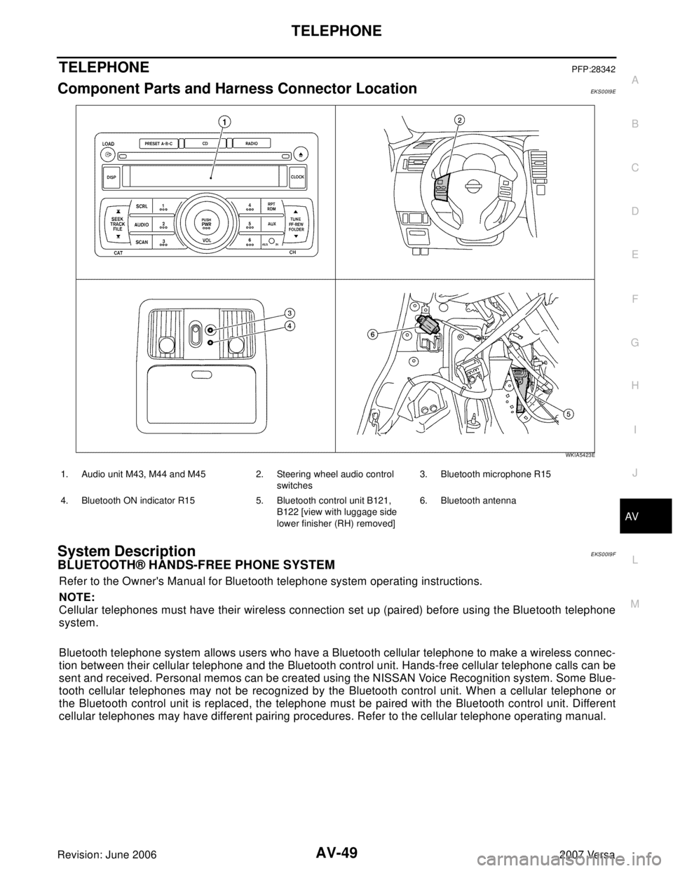
Component Parts and Harness Connector LocationEKS00I9E
System DescriptionEKS00I9F
BLUETOOTH® HANDS-FREE PHONE SYSTEM
Refer to the Owner's Manual for Bluetooth telephone system operating instructions.
NOTE:
Cellular telephones must have their wireless connection set up (paired) before using the Bluetooth telephone
system.
Bluetooth telephone system allows users who have a Bluetooth cellular telephone to make a wireless connec-
tion between their cellular telephone and the Bluetooth control unit. Hands-free cellular telephone calls can be
sent and received. Personal memos can be created using the NISSAN Voice Recognition system. Some Blue-
tooth cellular telephones may not be recognized by the Bluetooth control unit. When a cellular telephone or
the Bluetooth control unit is replaced, the telephone must be paired with the Bluetooth control unit. Different
cellular telephones may have different pairing procedures. Refer to the cellular telephone operating manual.
WKIA5423E
1. Audio unit M43, M44 and M45 2. Steering wheel audio control
switches3. Bluetooth microphone R15
4. Bluetooth ON indicator R15 5. Bluetooth control unit B121,
B122 [view with luggage side
lower finisher (RH) removed]6. Bluetooth antenna