Page 627 of 2896
BL-138
INTELLIGENT KEY SYSTEM
Revision: June 20062007 Versa
Intelligent Key Warning Buzzer (Driver Door) CheckEIS0092K
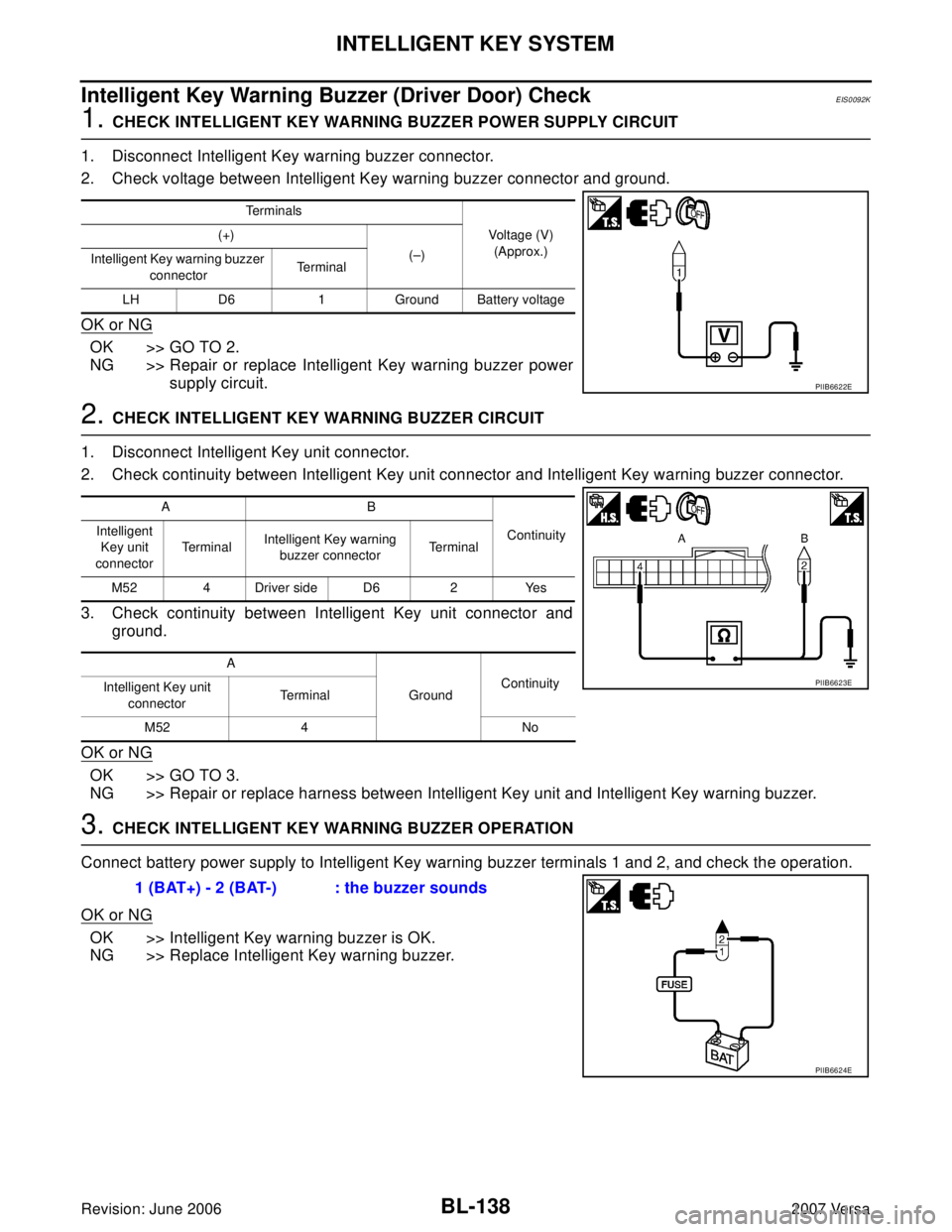
1. CHECK INTELLIGENT KEY WARNING BUZZER POWER SUPPLY CIRCUIT
1. Disconnect Intelligent Key warning buzzer connector.
2. Check voltage between Intelligent Key warning buzzer connector and ground.
OK or NG
OK >> GO TO 2.
NG >> Repair or replace Intelligent Key warning buzzer power
supply circuit.
2. CHECK INTELLIGENT KEY WARNING BUZZER CIRCUIT
1. Disconnect Intelligent Key unit connector.
2. Check continuity between Intelligent Key unit connector and Intelligent Key warning buzzer connector.
3. Check continuity between Intelligent Key unit connector and
ground.
OK or NG
OK >> GO TO 3.
NG >> Repair or replace harness between Intelligent Key unit and Intelligent Key warning buzzer.
3. CHECK INTELLIGENT KEY WARNING BUZZER OPERATION
Connect battery power supply to Intelligent Key warning buzzer terminals 1 and 2, and check the operation.
OK or NG
OK >> Intelligent Key warning buzzer is OK.
NG >> Replace Intelligent Key warning buzzer.
Terminals
Voltage (V)
(Approx.) (+)
(–)
Intelligent Key warning buzzer
connectorTe r m i n a l
LH D6 1 Ground Battery voltage
PIIB6622E
AB
Continuity Intelligent
Key unit
connectorTerminalIntelligent Key warning
buzzer connectorTe r m i n a l
M52 4 Driver side D6 2 Yes
A
GroundContinuity
Intelligent Key unit
connectorTe r m i n a l
M52 4 No
PIIB6623E
1 (BAT+) - 2 (BAT-) : the buzzer sounds
PIIB6624E
Page 642 of 2896
INTELLIGENT KEY SYSTEM
BL-153
C
D
E
F
G
H
J
K
L
MA
B
BL
Revision: June 20062007 Versa
“P-SHIFT” Warning Lamp (With CVT) CheckEIS009DB
1. CHECK WARNING LAMP OPERATION
With CONSULT-II
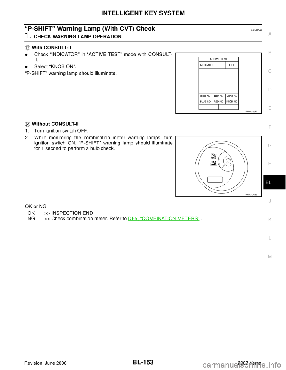
�Check “INDICATOR” in “ACTIVE TEST” mode with CONSULT-
II.
�Select “KNOB ON”.
“P-SHIFT” warning lamp should illuminate.
Without CONSULT-II
1. Turn ignition switch OFF.
2. While monitoring the combination meter warning lamps, turn
ignition switch ON. "P-SHIFT" warning lamp should illuminate
for 1 second to perform a bulb check.
OK or NG
OK >> INSPECTION END
NG >> Check combination meter. Refer to DI-5, "
COMBINATION METERS" .
PIIB4356E
WIIA1262E
Page 643 of 2896
BL-154
INTELLIGENT KEY SYSTEM
Revision: June 20062007 Versa
“LOCK” Warning Lamp (With M/T) CheckEIS009DC
1. CHECK WARNING LAMP OPERATION
With CONSULT-II
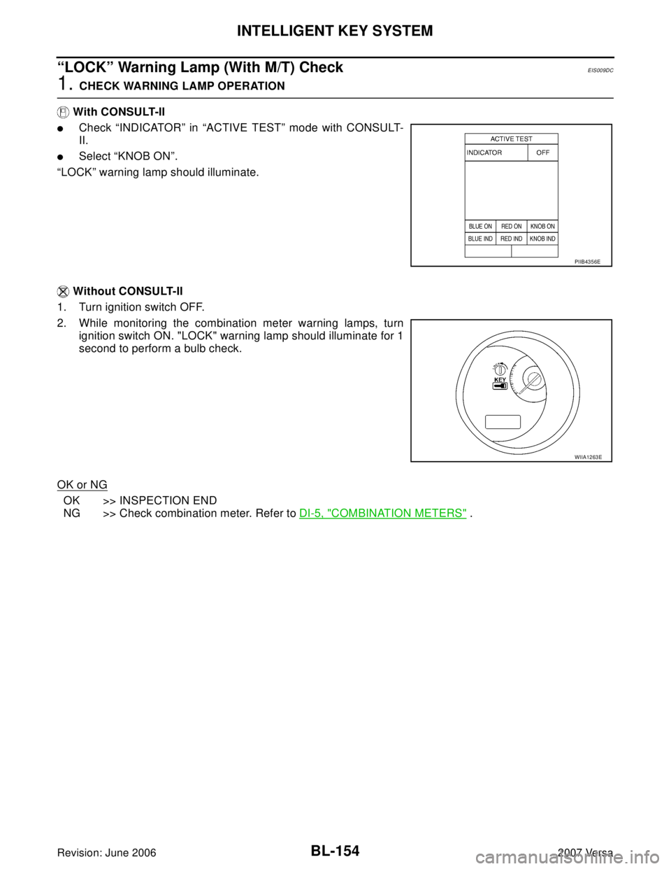
�Check “INDICATOR” in “ACTIVE TEST” mode with CONSULT-
II.
�Select “KNOB ON”.
“LOCK” warning lamp should illuminate.
Without CONSULT-II
1. Turn ignition switch OFF.
2. While monitoring the combination meter warning lamps, turn
ignition switch ON. "LOCK" warning lamp should illuminate for 1
second to perform a bulb check.
OK or NG
OK >> INSPECTION END
NG >> Check combination meter. Refer to DI-5, "
COMBINATION METERS" .
PIIB4356E
WIIA1263E
Page 644 of 2896
INTELLIGENT KEY SYSTEM
BL-155
C
D
E
F
G
H
J
K
L
MA
B
BL
Revision: June 20062007 Versa
“KEY” Warning Lamp (RED) CheckEIS009DD
1. CHECK WARNING LAMP OPERATION
With CONSULT-II
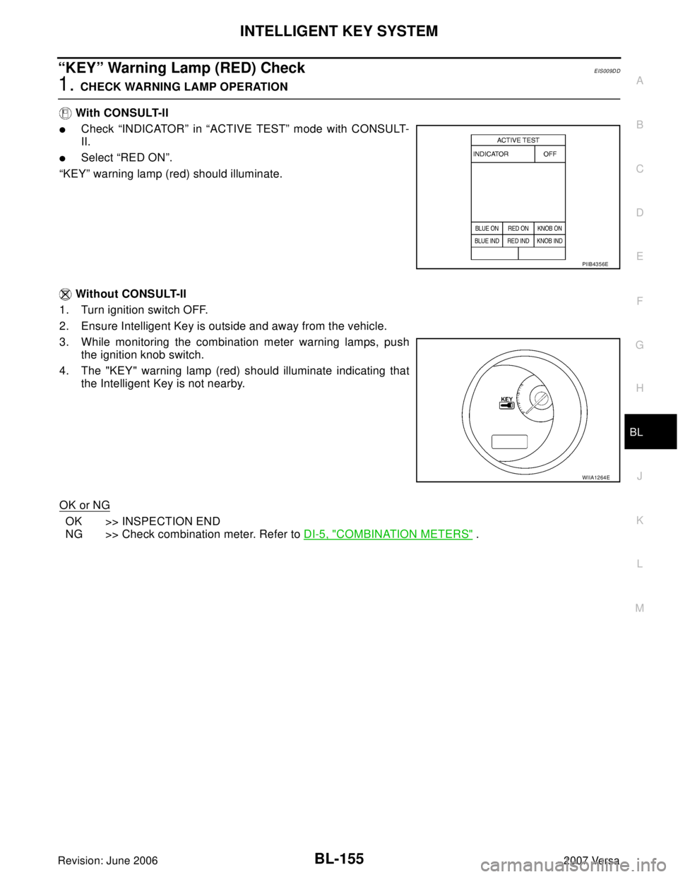
�Check “INDICATOR” in “ACTIVE TEST” mode with CONSULT-
II.
�Select “RED ON”.
“KEY” warning lamp (red) should illuminate.
Without CONSULT-II
1. Turn ignition switch OFF.
2. Ensure Intelligent Key is outside and away from the vehicle.
3. While monitoring the combination meter warning lamps, push
the ignition knob switch.
4. The "KEY" warning lamp (red) should illuminate indicating that
the Intelligent Key is not nearby.
OK or NG
OK >> INSPECTION END
NG >> Check combination meter. Refer to DI-5, "
COMBINATION METERS" .
PIIB4356E
WIIA1264E
Page 645 of 2896
BL-156
INTELLIGENT KEY SYSTEM
Revision: June 20062007 Versa
“KEY” Warning Lamp (GREEN) CheckEIS009DE
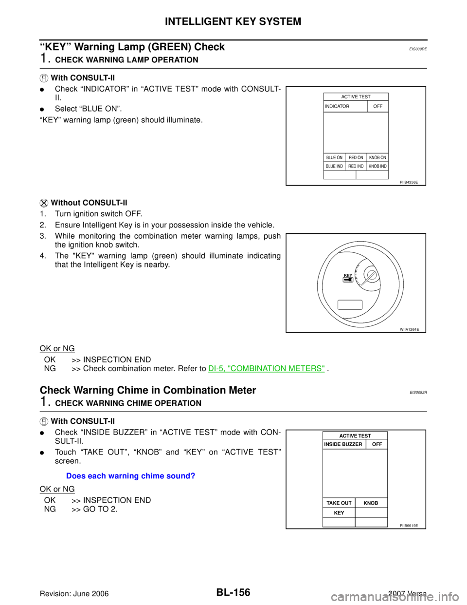
1. CHECK WARNING LAMP OPERATION
With CONSULT-II
�Check “INDICATOR” in “ACTIVE TEST” mode with CONSULT-
II.
�Select “BLUE ON”.
“KEY” warning lamp (green) should illuminate.
Without CONSULT-II
1. Turn ignition switch OFF.
2. Ensure Intelligent Key is in your possession inside the vehicle.
3. While monitoring the combination meter warning lamps, push
the ignition knob switch.
4. The "KEY" warning lamp (green) should illuminate indicating
that the Intelligent Key is nearby.
OK or NG
OK >> INSPECTION END
NG >> Check combination meter. Refer to DI-5, "
COMBINATION METERS" .
Check Warning Chime in Combination MeterEIS0092R
1. CHECK WARNING CHIME OPERATION
With CONSULT-II
�Check “INSIDE BUZZER” in “ACTIVE TEST” mode with CON-
SULT-II.
�Touch “TAKE OUT”, “KNOB” and “KEY” on “ACTIVE TEST”
screen.
OK or NG
OK >> INSPECTION END
NG >> GO TO 2.
PIIB4356E
WIIA1264E
Does each warning chime sound?
PIIB6619E
Page 646 of 2896
INTELLIGENT KEY SYSTEM
BL-157
C
D
E
F
G
H
J
K
L
MA
B
BL
Revision: June 20062007 Versa
2. CHECK OTHER WARNING CHIME OPERATION
Check other warning chime operation using combination meter.
OK or NG
OK >> INSPECTION END
NG >> GO TO DI-47, "
WARNING CHIME" .
Hazard Function CheckEIS0092S
1. CHECK HAZARD WARNING LAMP
Do hazard warning lamps flash with hazard switch?
YES or NO
YES >> Hazard warning lamp circuit is OK.
NO >> Check hazard circuit. Refer to LT- 5 1 , "
TURN SIGNAL AND HAZARD WARNING LAMPS" .
Horn Function CheckEIS0092T
First perform the “SELF-DIAG RESULTS” of “BCM” with CONSULT-II, then perform the trouble diagno-
sis of malfunction system indicated in “SELF-DIAG RESULTS” of “BCM”. Refer to BCS-18, "
CAN Com-
munication Inspection Using CONSULT-II (Self-Diagnosis)".
1. CHECK HORN OPERATION
Check if horn sounds with horn switch.
Does horn operate?
Yes >> GO TO 2.
No >> Check horn circuit. Refer to WW-46, "
HORN" .
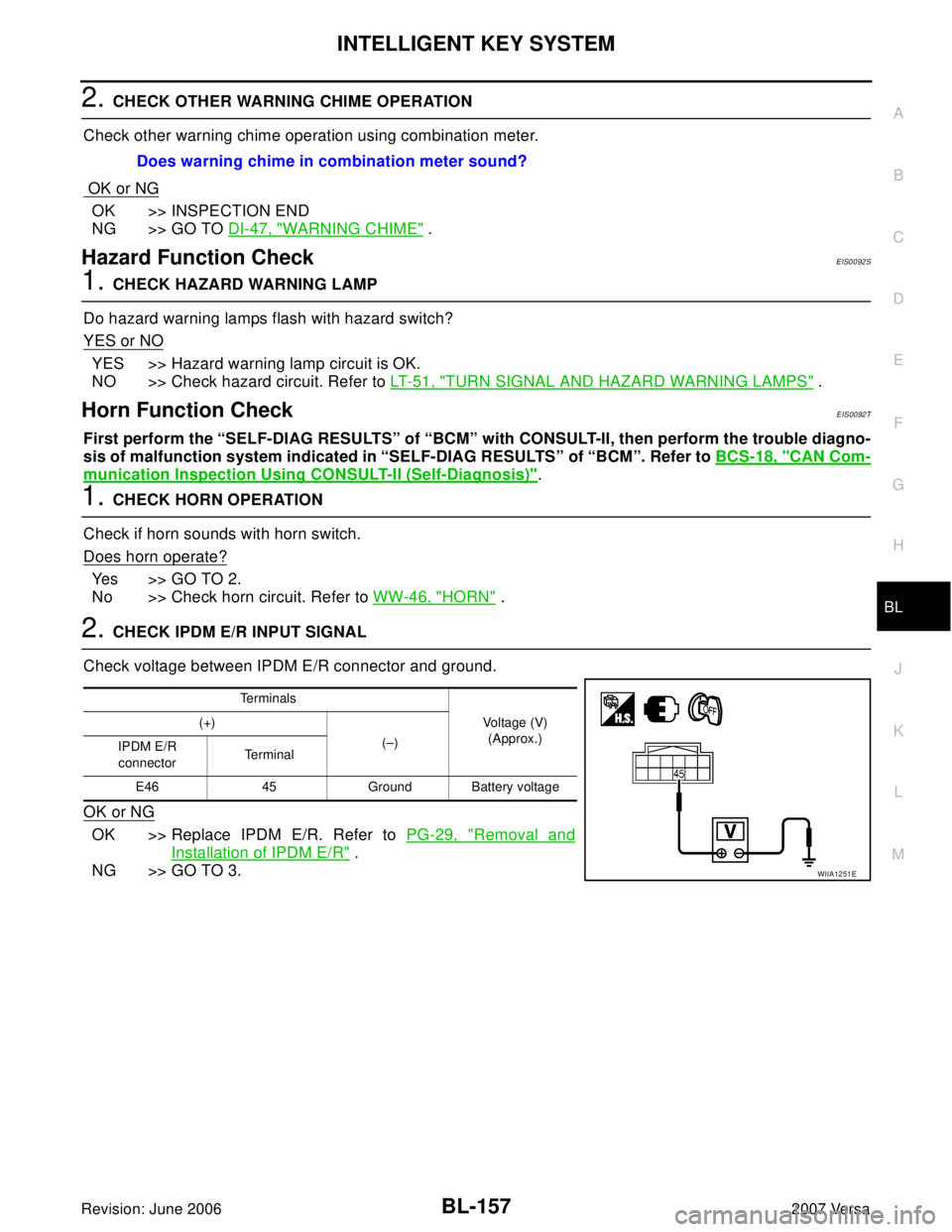
2. CHECK IPDM E/R INPUT SIGNAL
Check voltage between IPDM E/R connector and ground.
OK or NG
OK >> Replace IPDM E/R. Refer to PG-29, "Removal and
Installation of IPDM E/R" .
NG >> GO TO 3.Does warning chime in combination meter sound?
Te r m i n a l s
Voltage (V)
(Approx.) (+)
(–)
IPDM E/R
connectorTe r m i n a l
E46 45 Ground Battery voltage
WIIA1251E
Page 682 of 2896
VEHICLE SECURITY (THEFT WARNING) SYSTEM
BL-193
C
D
E
F
G
H
J
K
L
MA
B
BL
Revision: June 20062007 Versa
VEHICLE SECURITY (THEFT WARNING) SYSTEMPFP:28491
Component Parts and Harness Connector LocationEIS009AX
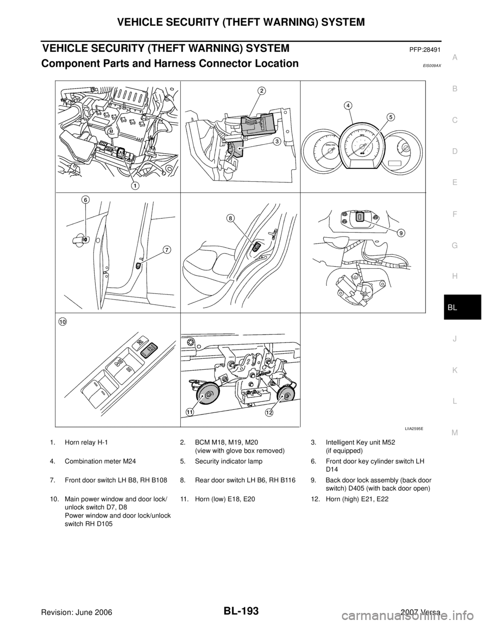
LIIA2595E
1. Horn relay H-1 2. BCM M18, M19, M20
(view with glove box removed)3. Intelligent Key unit M52
(if equipped)
4. Combination meter M24 5. Security indicator lamp 6. Front door key cylinder switch LH
D14
7. Front door switch LH B8, RH B108 8. Rear door switch LH B6, RH B116 9. Back door lock assembly (back door
switch) D405 (with back door open)
10. Main power window and door lock/
unlock switch D7, D8
Power window and door lock/unlock
switch RH D10511. Horn (low) E18, E20 12. Horn (high) E21, E22
Page 683 of 2896
BL-194
VEHICLE SECURITY (THEFT WARNING) SYSTEM
Revision: June 20062007 Versa
System DescriptionEIS009AY
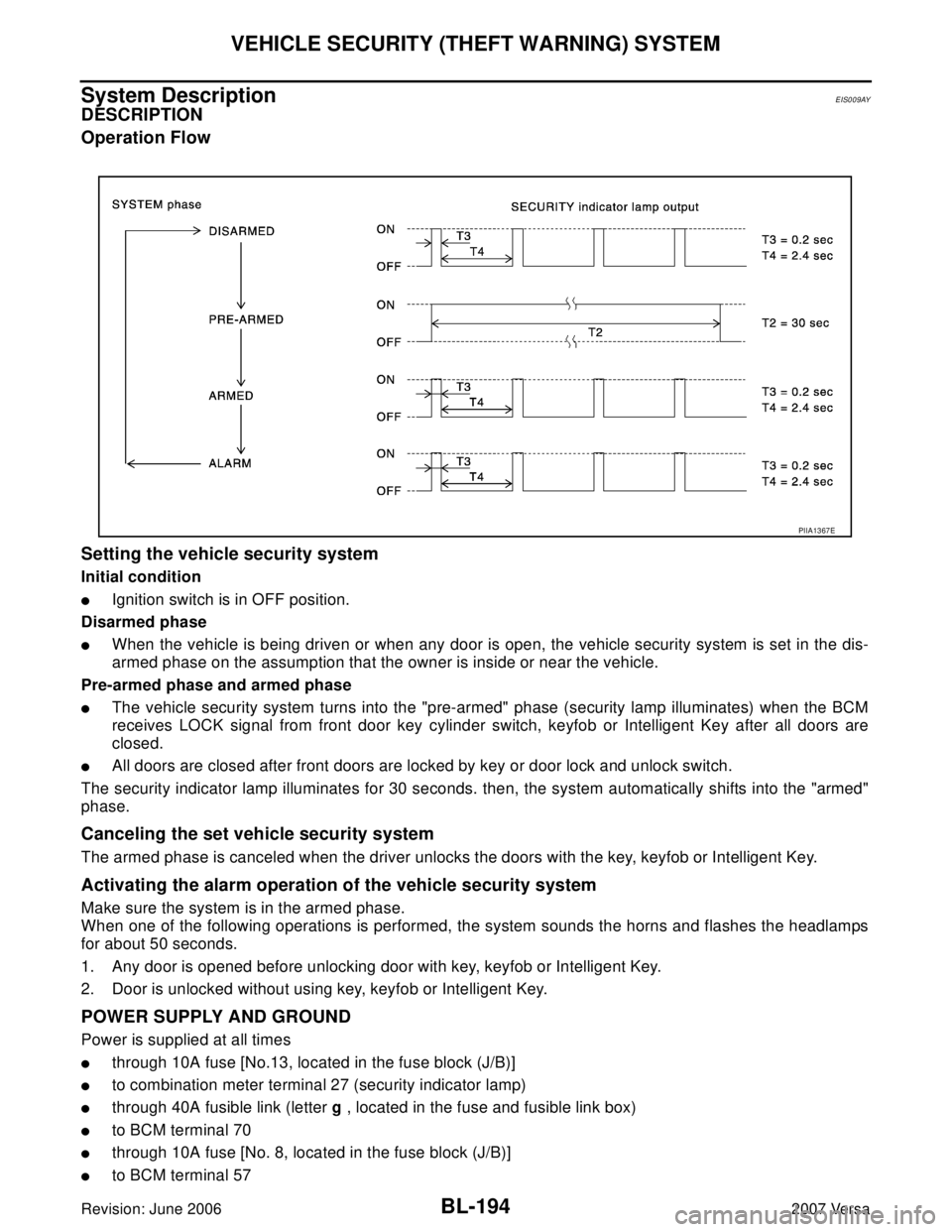
DESCRIPTION
Operation Flow
Setting the vehicle security system
Initial condition
�Ignition switch is in OFF position.
Disarmed phase
�When the vehicle is being driven or when any door is open, the vehicle security system is set in the dis-
armed phase on the assumption that the owner is inside or near the vehicle.
Pre-armed phase and armed phase
�The vehicle security system turns into the "pre-armed" phase (security lamp illuminates) when the BCM
receives LOCK signal from front door key cylinder switch, keyfob or Intelligent Key after all doors are
closed.
�All doors are closed after front doors are locked by key or door lock and unlock switch.
The security indicator lamp illuminates for 30 seconds. then, the system automatically shifts into the "armed"
phase.
Canceling the set vehicle security system
The armed phase is canceled when the driver unlocks the doors with the key, keyfob or Intelligent Key.
Activating the alarm operation of the vehicle security system
Make sure the system is in the armed phase.
When one of the following operations is performed, the system sounds the horns and flashes the headlamps
for about 50 seconds.
1. Any door is opened before unlocking door with key, keyfob or Intelligent Key.
2. Door is unlocked without using key, keyfob or Intelligent Key.
POWER SUPPLY AND GROUND
Power is supplied at all times
�through 10A fuse [No.13, located in the fuse block (J/B)]
�to combination meter terminal 27 (security indicator lamp)
�through 40A fusible link (letter g , located in the fuse and fusible link box)
�to BCM terminal 70
�through 10A fuse [No. 8, located in the fuse block (J/B)]
�to BCM terminal 57
PIIA1367E