Page 1080 of 2896
TROUBLE DIAGNOSIS FOR SYMPTOMS
CVT-183
D
E
F
G
H
I
J
K
L
MA
B
CVT
Revision: June 20062007 Versa
5. CHECK TCM
1. Check TCM input/output signals. Refer to CVT-54, "
TCM Input/Output Signal Reference Values" .
2. If NG, re-check TCM pin terminals for damage or loose connection with harness connector.
OK or NG
OK >> Replace the transaxle assembly. Refer to CVT-207, "Removal and Installation" .
NG >> Repair or replace damaged parts.
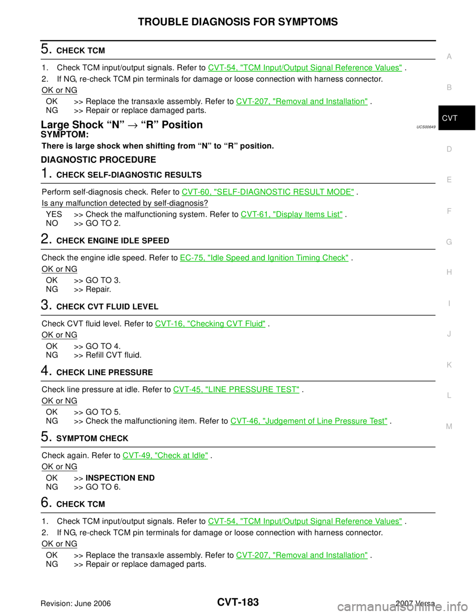
Large Shock “N” → “R” PositionUCS00649
SYMPTOM:
There is large shock when shifting from “N” to “R” position.
DIAGNOSTIC PROCEDURE
1. CHECK SELF-DIAGNOSTIC RESULTS
Perform self-diagnosis check. Refer to CVT-60, "
SELF-DIAGNOSTIC RESULT MODE" .
Is any malfunction detected by self-diagnosis?
YES >> Check the malfunctioning system. Refer to CVT-61, "Display Items List" .
NO >> GO TO 2.
2. CHECK ENGINE IDLE SPEED
Check the engine idle speed. Refer to EC-75, "
Idle Speed and Ignition Timing Check" .
OK or NG
OK >> GO TO 3.
NG >> Repair.
3. CHECK CVT FLUID LEVEL
Check CVT fluid level. Refer to CVT-16, "
Checking CVT Fluid" .
OK or NG
OK >> GO TO 4.
NG >> Refill CVT fluid.
4. CHECK LINE PRESSURE
Check line pressure at idle. Refer to CVT-45, "
LINE PRESSURE TEST" .
OK or NG
OK >> GO TO 5.
NG >> Check the malfunctioning item. Refer to CVT-46, "
Judgement of Line Pressure Test" .
5. SYMPTOM CHECK
Check again. Refer to CVT-49, "
Check at Idle" .
OK or NG
OK >>INSPECTION END
NG >> GO TO 6.
6. CHECK TCM
1. Check TCM input/output signals. Refer to CVT-54, "
TCM Input/Output Signal Reference Values" .
2. If NG, re-check TCM pin terminals for damage or loose connection with harness connector.
OK or NG
OK >> Replace the transaxle assembly. Refer to CVT-207, "Removal and Installation" .
NG >> Repair or replace damaged parts.
Page 1086 of 2896
TROUBLE DIAGNOSIS FOR SYMPTOMS
CVT-189
D
E
F
G
H
I
J
K
L
MA
B
CVT
Revision: June 20062007 Versa
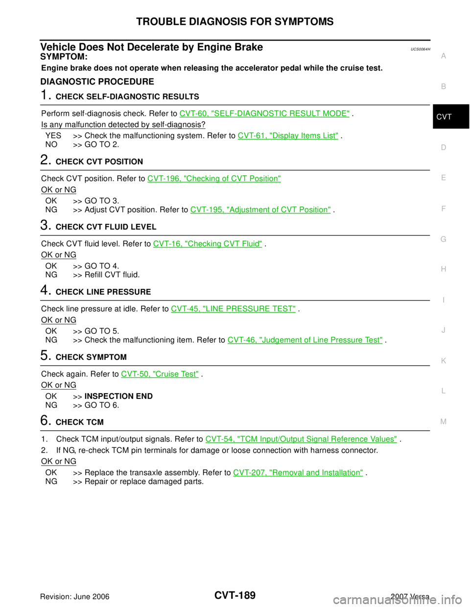
Vehicle Does Not Decelerate by Engine BrakeUCS0064H
SYMPTOM:
Engine brake does not operate when releasing the accelerator pedal while the cruise test.
DIAGNOSTIC PROCEDURE
1. CHECK SELF-DIAGNOSTIC RESULTS
Perform self-diagnosis check. Refer to CVT-60, "
SELF-DIAGNOSTIC RESULT MODE" .
Is any malfunction detected by self-diagnosis?
YES >> Check the malfunctioning system. Refer to CVT-61, "Display Items List" .
NO >> GO TO 2.
2. CHECK CVT POSITION
Check CVT position. Refer to CVT-196, "
Checking of CVT Position"
OK or NG
OK >> GO TO 3.
NG >> Adjust CVT position. Refer to CVT-195, "
Adjustment of CVT Position" .
3. CHECK CVT FLUID LEVEL
Check CVT fluid level. Refer to CVT-16, "
Checking CVT Fluid" .
OK or NG
OK >> GO TO 4.
NG >> Refill CVT fluid.
4. CHECK LINE PRESSURE
Check line pressure at idle. Refer to CVT-45, "
LINE PRESSURE TEST" .
OK or NG
OK >> GO TO 5.
NG >> Check the malfunctioning item. Refer to CVT-46, "
Judgement of Line Pressure Test" .
5. CHECK SYMPTOM
Check again. Refer to CVT-50, "
Cruise Test" .
OK or NG
OK >>INSPECTION END
NG >> GO TO 6.
6. CHECK TCM
1. Check TCM input/output signals. Refer to CVT-54, "
TCM Input/Output Signal Reference Values" .
2. If NG, re-check TCM pin terminals for damage or loose connection with harness connector.
OK or NG
OK >> Replace the transaxle assembly. Refer to CVT-207, "Removal and Installation" .
NG >> Repair or replace damaged parts.
Page 1093 of 2896
CVT-196
SHIFT CONTROL SYSTEM
Revision: June 20062007 Versa
Checking of CVT PositionUCS0064K
1. Place selector lever in “P” position, and turn ignition switch ON. (Do not start engine.)
2. Make sure selector lever can be shifted to other than “P” position when brake pedal is depressed. Also
make sure selector lever can be shifted from “P” position only when brake pedal is depressed.
3. Move the selector lever and check for excessive effort, sticking, noise or rattle.
4. Confirm the selector lever stops at each position with the feel of engagement when it is moved through all
the positions. Check that the actual position of the selector lever matches the position shown by the shift
position indicator and the manual lever on the transaxle.
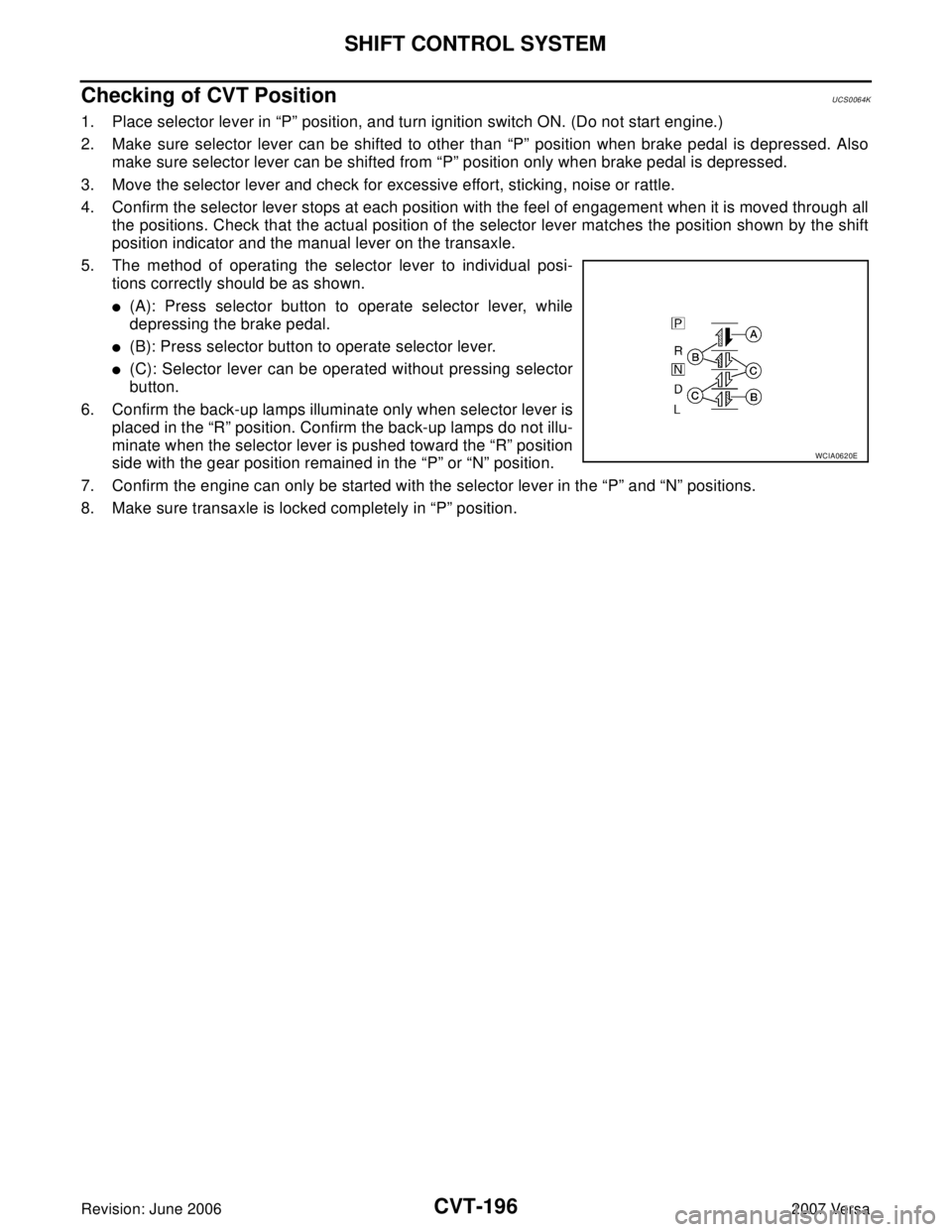
5. The method of operating the selector lever to individual posi-
tions correctly should be as shown.
�(A): Press selector button to operate selector lever, while
depressing the brake pedal.
�(B): Press selector button to operate selector lever.
�(C): Selector lever can be operated without pressing selector
button.
6. Confirm the back-up lamps illuminate only when selector lever is
placed in the “R” position. Confirm the back-up lamps do not illu-
minate when the selector lever is pushed toward the “R” position
side with the gear position remained in the “P” or “N” position.
7. Confirm the engine can only be started with the selector lever in the “P” and “N” positions.
8. Make sure transaxle is locked completely in “P” position.
WCIA0620E
Page 1096 of 2896
CVT SHIFT LOCK SYSTEM
CVT-199
D
E
F
G
H
I
J
K
L
MA
B
CVT
Revision: June 20062007 Versa
Diagnostic ProcedureUCS006KN
SYMPTOM 1:
�Selector lever cannot be moved from “P” position with ignition switch in ON position and brake
pedal depressed.
�Selector lever can be moved from “P” position with ignition key in ON position and brake pedal
released.
�Selector lever can be moved from “P” position when ignition switch is removed from key cylinder.
SYMPTOM 2:
�Ignition key cannot be removed when selector lever is set to “P” position.
�Ignition key can be removed when selector lever is set to any position except “P” position.
1. CHECK KEY INTERLOCK CABLE
Check key interlock cable for damage.
OK or NG
OK >> GO TO 2.
NG >> Repair key interlock cable. Refer to AT-239, "
Removal and Installation" .
2. CHECK CVT POSITION
Check CVT position. Refer to CVT-196, "
Checking of CVT Position" .
OK or NG
OK >> GO TO 3.
NG >> Adjust control cable. Refer to CVT-195, "
Adjustment of CVT Position" .
3. CHECK SHIFT LOCK SOLENOID AND PARK POSITION SWITCH
1. Turn ignition switch ON. (Do not start engine.)
2. Selector lever is set in “P” position.
3. Check operation sound.
OK or NG
OK >>INSPECTION END
NG - 1 >> With intelligent key: GO TO 4.
NG - 2 >> Without intelligent key: GO TO 5.
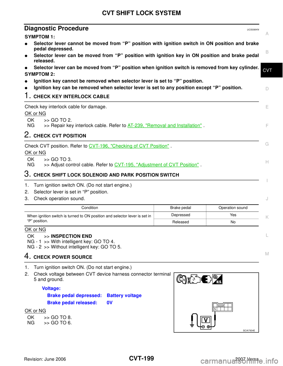
4. CHECK POWER SOURCE
1. Turn ignition switch ON. (Do not start engine.)
2. Check voltage between CVT device harness connector terminal
5 and ground.
OK or NG
OK >> GO TO 8.
NG >> GO TO 6.
Condition Brake pedal Operation sound
When ignition switch is turned to ON position and selector lever is set in
“P” position.Depressed Yes
Released No
Voltage:
Brake pedal depressed: Battery voltage
Brake pedal released: 0V
SCIA7934E
Page 1097 of 2896
CVT-200
CVT SHIFT LOCK SYSTEM
Revision: June 20062007 Versa
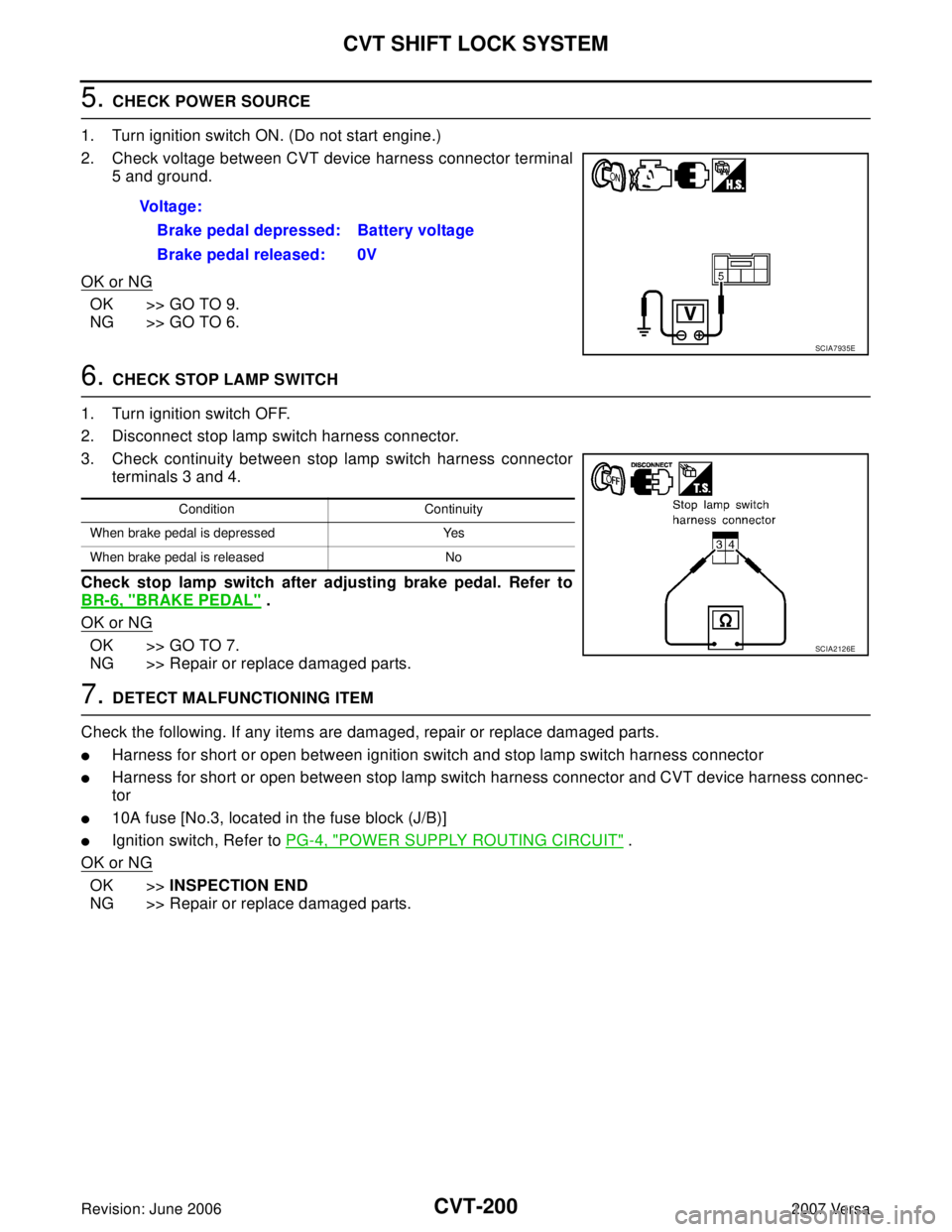
5. CHECK POWER SOURCE
1. Turn ignition switch ON. (Do not start engine.)
2. Check voltage between CVT device harness connector terminal
5 and ground.
OK or NG
OK >> GO TO 9.
NG >> GO TO 6.
6. CHECK STOP LAMP SWITCH
1. Turn ignition switch OFF.
2. Disconnect stop lamp switch harness connector.
3. Check continuity between stop lamp switch harness connector
terminals 3 and 4.
Check stop lamp switch after adjusting brake pedal. Refer to
BR-6, "
BRAKE PEDAL" .
OK or NG
OK >> GO TO 7.
NG >> Repair or replace damaged parts.
7. DETECT MALFUNCTIONING ITEM
Check the following. If any items are damaged, repair or replace damaged parts.
�Harness for short or open between ignition switch and stop lamp switch harness connector
�Harness for short or open between stop lamp switch harness connector and CVT device harness connec-
tor
�10A fuse [No.3, located in the fuse block (J/B)]
�Ignition switch, Refer to PG-4, "POWER SUPPLY ROUTING CIRCUIT" .
OK or NG
OK >>INSPECTION END
NG >> Repair or replace damaged parts. Voltage:
Brake pedal depressed: Battery voltage
Brake pedal released: 0V
SCIA7935E
Condition Continuity
When brake pedal is depressed Yes
When brake pedal is released No
SCIA2126E
Page 1104 of 2896
TRANSAXLE ASSEMBLY
CVT-207
D
E
F
G
H
I
J
K
L
MA
B
CVT
Revision: June 20062007 Versa
TRANSAXLE ASSEMBLYPFP:32020
Removal and InstallationUCS0064V
COMPONENTS
REMOVAL
1. Remove the engine and transaxle as an assembly. Refer to EM-73, "Removal and Installation" .
2. Disconnect the secondary speed sensor connector (A) and CVT
unit connector (B). Refer to CVT-11, "
Removal and Installation
Procedure for CVT Unit Connector" .
3. Remove the harness from the transaxle.
1. CVT fluid level gauge 2. CVT fluid charging pipe 3. O-ring
4. Copper washer 5. Fluid cooler tube 6. Transaxle assembly
7. Engine mounting bracket (LH) 8. Air breather hose A. Refer to CVT-208, "
INSTALLA-
TION" .
WCIA0614E
WCIA0615E
Page 1105 of 2896
CVT-208
TRANSAXLE ASSEMBLY
Revision: June 20062007 Versa
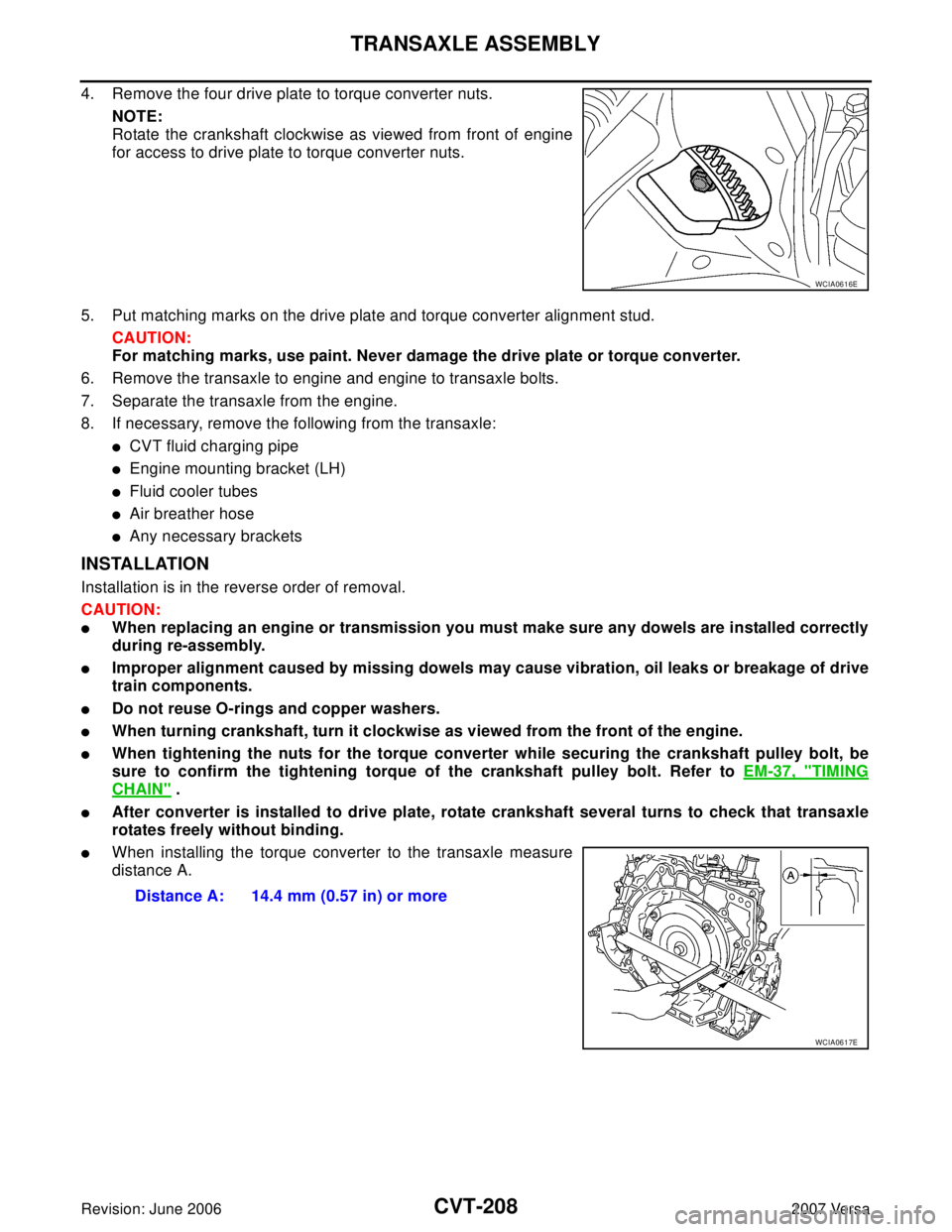
4. Remove the four drive plate to torque converter nuts.
NOTE:
Rotate the crankshaft clockwise as viewed from front of engine
for access to drive plate to torque converter nuts.
5. Put matching marks on the drive plate and torque converter alignment stud.
CAUTION:
For matching marks, use paint. Never damage the drive plate or torque converter.
6. Remove the transaxle to engine and engine to transaxle bolts.
7. Separate the transaxle from the engine.
8. If necessary, remove the following from the transaxle:
�CVT fluid charging pipe
�Engine mounting bracket (LH)
�Fluid cooler tubes
�Air breather hose
�Any necessary brackets
INSTALLATION
Installation is in the reverse order of removal.
CAUTION:
�When replacing an engine or transmission you must make sure any dowels are installed correctly
during re-assembly.
�Improper alignment caused by missing dowels may cause vibration, oil leaks or breakage of drive
train components.
�Do not reuse O-rings and copper washers.
�When turning crankshaft, turn it clockwise as viewed from the front of the engine.
�When tightening the nuts for the torque converter while securing the crankshaft pulley bolt, be
sure to confirm the tightening torque of the crankshaft pulley bolt. Refer to EM-37, "
TIMING
CHAIN" .
�After converter is installed to drive plate, rotate crankshaft several turns to check that transaxle
rotates freely without binding.
�When installing the torque converter to the transaxle measure
distance A.
WCIA0616E
Distance A: 14.4 mm (0.57 in) or more
WCIA0617E
Page 1106 of 2896
TRANSAXLE ASSEMBLY
CVT-209
D
E
F
G
H
I
J
K
L
MA
B
CVT
Revision: June 20062007 Versa
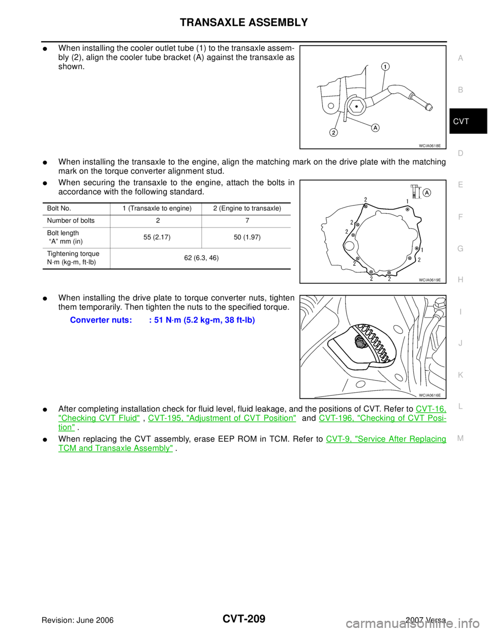
�When installing the cooler outlet tube (1) to the transaxle assem-
bly (2), align the cooler tube bracket (A) against the transaxle as
shown.
�When installing the transaxle to the engine, align the matching mark on the drive plate with the matching
mark on the torque converter alignment stud.
�When securing the transaxle to the engine, attach the bolts in
accordance with the following standard.
�When installing the drive plate to torque converter nuts, tighten
them temporarily. Then tighten the nuts to the specified torque.
�After completing installation check for fluid level, fluid leakage, and the positions of CVT. Refer to CVT-16,
"Checking CVT Fluid" , CVT-195, "Adjustment of CVT Position" and CVT-196, "Checking of CVT Posi-
tion" .
�When replacing the CVT assembly, erase EEP ROM in TCM. Refer to CVT-9, "Service After Replacing
TCM and Transaxle Assembly" .
WCIA0618E
Bolt No. 1 (Transaxle to engine) 2 (Engine to transaxle)
Number of bolts 2 7
Bolt length
“A” mm (in)55 (2.17) 50 (1.97)
Tightening torque
N·m (kg-m, ft-lb)62 (6.3, 46)
WCIA0619E
Converter nuts: : 51 N·m (5.2 kg-m, 38 ft-lb)
WCIA0616E