Page 1409 of 2896
EC-240Revision: June 2006
DTC P0133 A/F SENSOR 1
2007 Versa
DTC Confirmation ProcedureUBS00QFA
NOTE:
If DTC Confirmation Procedure has been previously conducted, always turn ignition switch OFF and wait at
least 10 seconds before conducting the next test.
TESTING CONDITION:
Before performing the following procedure, confirm that battery voltage is more than 11V at idle.
WITH CONSULT-II
1. Start engine and warm it up to normal operating temperature.
2. Turn ignition switch OFF and wait at least 10 seconds.
3. Start engine and keep the engine speed between 3,500 and 4,000 rpm for at least 1minute under no load.
4. Let engine idle for 1 minute.
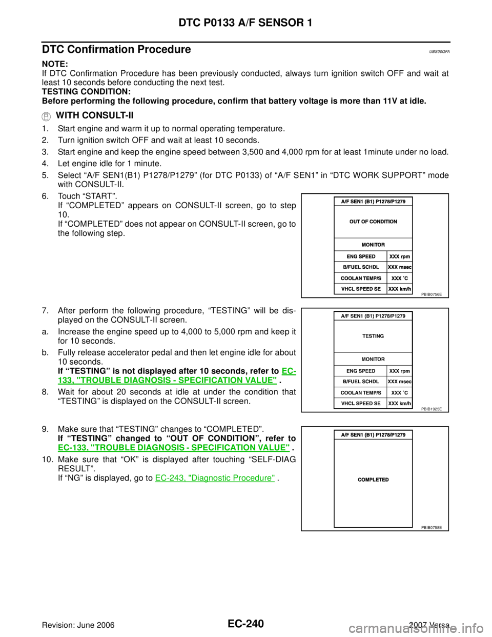
5. Select “A/F SEN1(B1) P1278/P1279” (for DTC P0133) of “A/F SEN1” in “DTC WORK SUPPORT” mode
with CONSULT-II.
6. Touch “START”.
If “COMPLETED” appears on CONSULT-II screen, go to step
10.
If “COMPLETED” does not appear on CONSULT-II screen, go to
the following step.
7. After perform the following procedure, “TESTING” will be dis-
played on the CONSULT-II screen.
a. Increase the engine speed up to 4,000 to 5,000 rpm and keep it
for 10 seconds.
b. Fully release accelerator pedal and then let engine idle for about
10 seconds.
If “TESTING” is not displayed after 10 seconds, refer to EC-
133, "TROUBLE DIAGNOSIS - SPECIFICATION VALUE" .
8. Wait for about 20 seconds at idle at under the condition that
“TESTING” is displayed on the CONSULT-II screen.
9. Make sure that “TESTING” changes to “COMPLETED”.
If “TESTING” changed to “OUT OF CONDITION”, refer to
EC-133, "
TROUBLE DIAGNOSIS - SPECIFICATION VALUE" .
10. Make sure that “OK” is displayed after touching “SELF-DIAG
RESULT”.
If “NG” is displayed, go to EC-243, "
Diagnostic Procedure" .
PBIB0756E
PBIB1925E
PBIB0758E
Page 1415 of 2896
EC-246Revision: June 2006
DTC P0133 A/F SENSOR 1
2007 Versa
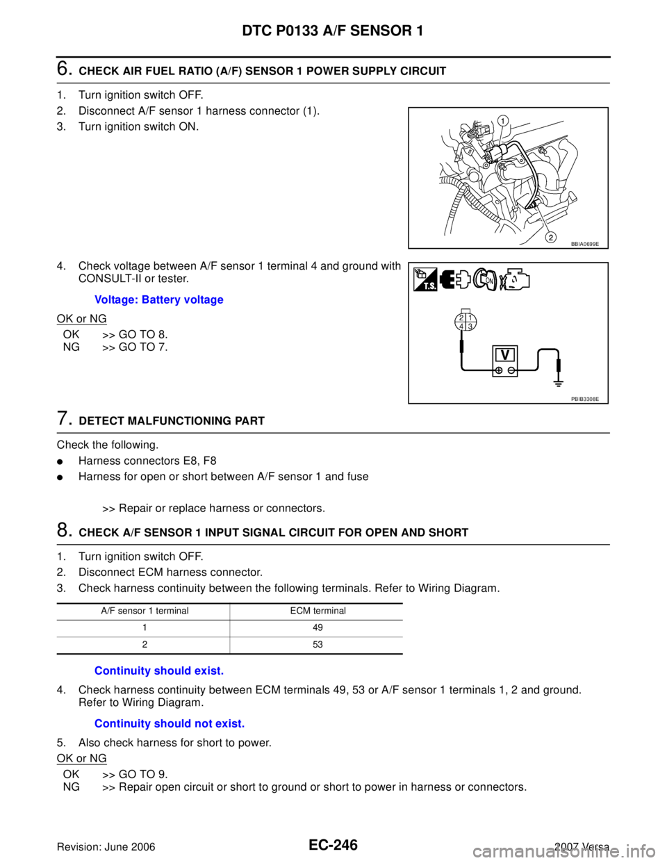
6. CHECK AIR FUEL RATIO (A/F) SENSOR 1 POWER SUPPLY CIRCUIT
1. Turn ignition switch OFF.
2. Disconnect A/F sensor 1 harness connector (1).
3. Turn ignition switch ON.
4. Check voltage between A/F sensor 1 terminal 4 and ground with
CONSULT-II or tester.
OK or NG
OK >> GO TO 8.
NG >> GO TO 7.
7. DETECT MALFUNCTIONING PART
Check the following.
�Harness connectors E8, F8
�Harness for open or short between A/F sensor 1 and fuse
>> Repair or replace harness or connectors.
8. CHECK A/F SENSOR 1 INPUT SIGNAL CIRCUIT FOR OPEN AND SHORT
1. Turn ignition switch OFF.
2. Disconnect ECM harness connector.
3. Check harness continuity between the following terminals. Refer to Wiring Diagram.
4. Check harness continuity between ECM terminals 49, 53 or A/F sensor 1 terminals 1, 2 and ground.
Refer to Wiring Diagram.
5. Also check harness for short to power.
OK or NG
OK >> GO TO 9.
NG >> Repair open circuit or short to ground or short to power in harness or connectors.
BBIA0699E
Voltage: Battery voltage
PBIB3308E
A/F sensor 1 terminal ECM terminal
149
253
Continuity should exist.
Continuity should not exist.
Page 1421 of 2896
EC-252Revision: June 2006
DTC P0137 HO2S2
2007 Versa
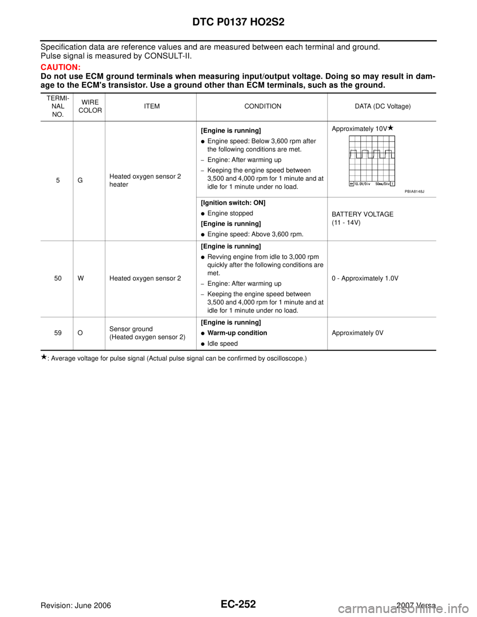
Specification data are reference values and are measured between each terminal and ground.
Pulse signal is measured by CONSULT-II.
CAUTION:
Do not use ECM ground terminals when measuring input/output voltage. Doing so may result in dam-
age to the ECM's transistor. Use a ground other than ECM terminals, such as the ground.
: Average voltage for pulse signal (Actual pulse signal can be confirmed by oscilloscope.) TERMI-
NAL
NO.WIRE
COLORITEM CONDITION DATA (DC Voltage)
5GHeated oxygen sensor 2
heater[Engine is running]
�Engine speed: Below 3,600 rpm after
the following conditions are met.
–Engine: After warming up
–Keeping the engine speed between
3,500 and 4,000 rpm for 1 minute and at
idle for 1 minute under no load.Approximately 10V
[Ignition switch: ON]
�Engine stopped
[Engine is running]
�Engine speed: Above 3,600 rpm.BATTERY VOLTAGE
(11 - 14V)
50 W Heated oxygen sensor 2[Engine is running]
�Revving engine from idle to 3,000 rpm
quickly after the following conditions are
met.
–Engine: After warming up
–Keeping the engine speed between
3,500 and 4,000 rpm for 1 minute and at
idle for 1 minute under no load.0 - Approximately 1.0V
59 OSensor ground
(Heated oxygen sensor 2)[Engine is running]
�Warm-up condition
�Idle speedApproximately 0V
PBIA8148J
Page 1430 of 2896
DTC P0138 HO2S2
EC-261
C
D
E
F
G
H
I
J
K
L
MA
EC
Revision: June 20062007 Versa
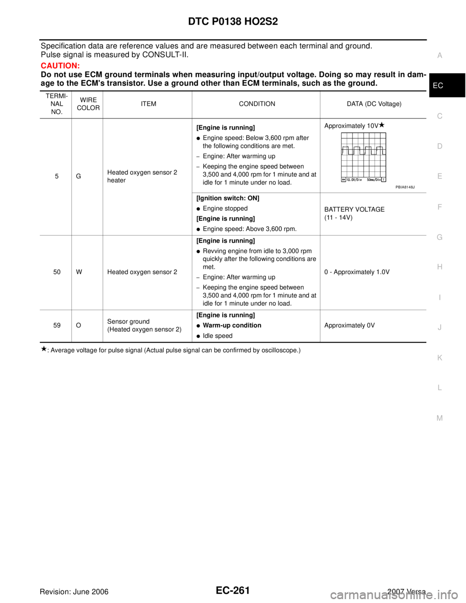
Specification data are reference values and are measured between each terminal and ground.
Pulse signal is measured by CONSULT-II.
CAUTION:
Do not use ECM ground terminals when measuring input/output voltage. Doing so may result in dam-
age to the ECM's transistor. Use a ground other than ECM terminals, such as the ground.
: Average voltage for pulse signal (Actual pulse signal can be confirmed by oscilloscope.) TERMI-
NAL
NO.WIRE
COLORITEM CONDITION DATA (DC Voltage)
5GHeated oxygen sensor 2
heater[Engine is running]
�Engine speed: Below 3,600 rpm after
the following conditions are met.
–Engine: After warming up
–Keeping the engine speed between
3,500 and 4,000 rpm for 1 minute and at
idle for 1 minute under no load.Approximately 10V
[Ignition switch: ON]
�Engine stopped
[Engine is running]
�Engine speed: Above 3,600 rpm.BATTERY VOLTAGE
(11 - 14V)
50 W Heated oxygen sensor 2[Engine is running]
�Revving engine from idle to 3,000 rpm
quickly after the following conditions are
met.
–Engine: After warming up
–Keeping the engine speed between
3,500 and 4,000 rpm for 1 minute and at
idle for 1 minute under no load.0 - Approximately 1.0V
59 OSensor ground
(Heated oxygen sensor 2)[Engine is running]
�Warm-up condition
�Idle speedApproximately 0V
PBIA8148J
Page 1440 of 2896
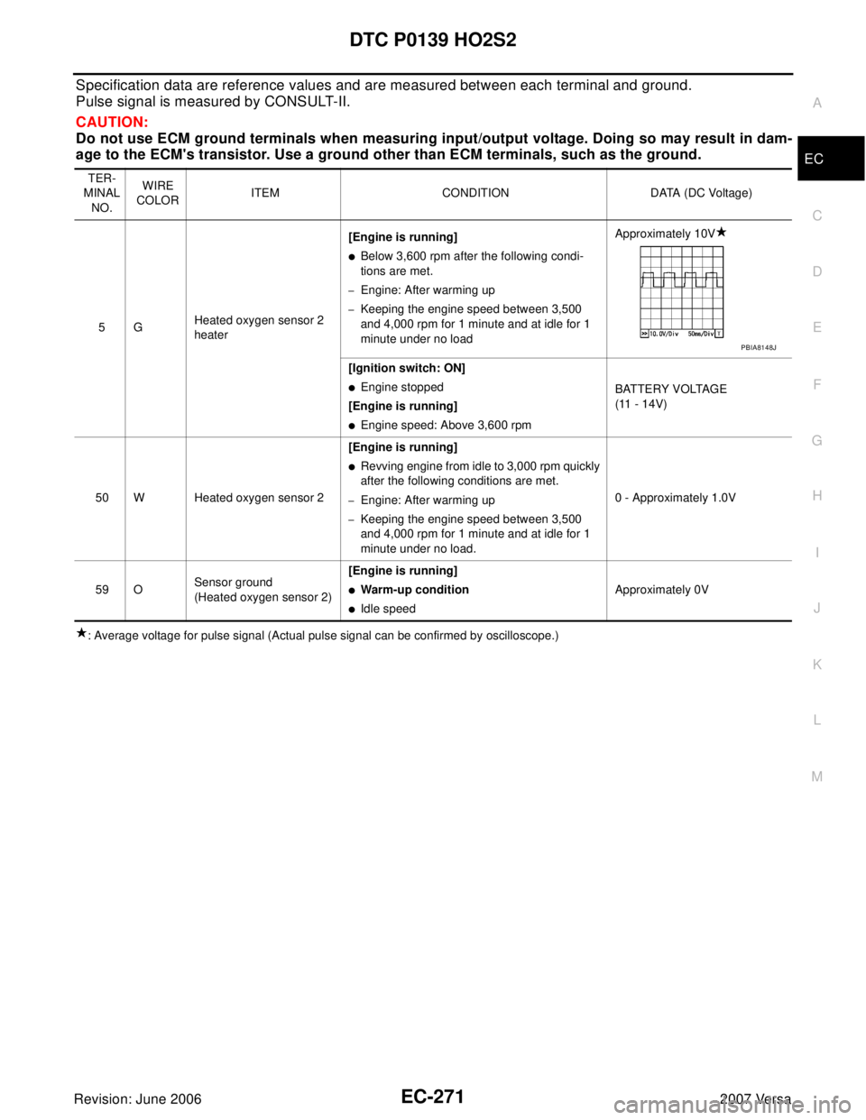
DTC P0139 HO2S2
EC-271
C
D
E
F
G
H
I
J
K
L
MA
EC
Revision: June 20062007 Versa
Specification data are reference values and are measured between each terminal and ground.
Pulse signal is measured by CONSULT-II.
CAUTION:
Do not use ECM ground terminals when measuring input/output voltage. Doing so may result in dam-
age to the ECM's transistor. Use a ground other than ECM terminals, such as the ground.
: Average voltage for pulse signal (Actual pulse signal can be confirmed by oscilloscope.)TER-
MINAL
NO.WIRE
COLORITEM CONDITION DATA (DC Voltage)
5GHeated oxygen sensor 2
heater[Engine is running]
�Below 3,600 rpm after the following condi-
tions are met.
–Engine: After warming up
–Keeping the engine speed between 3,500
and 4,000 rpm for 1 minute and at idle for 1
minute under no loadApproximately 10V
[Ignition switch: ON]
�Engine stopped
[Engine is running]
�Engine speed: Above 3,600 rpmBATTERY VOLTAGE
(11 - 14V)
50 W Heated oxygen sensor 2[Engine is running]
�Revving engine from idle to 3,000 rpm quickly
after the following conditions are met.
–Engine: After warming up
–Keeping the engine speed between 3,500
and 4,000 rpm for 1 minute and at idle for 1
minute under no load.0 - Approximately 1.0V
59 OSensor ground
(Heated oxygen sensor 2)[Engine is running]
�Warm-up condition
�Idle speedApproximately 0V
PBIA8148J
Page 1448 of 2896
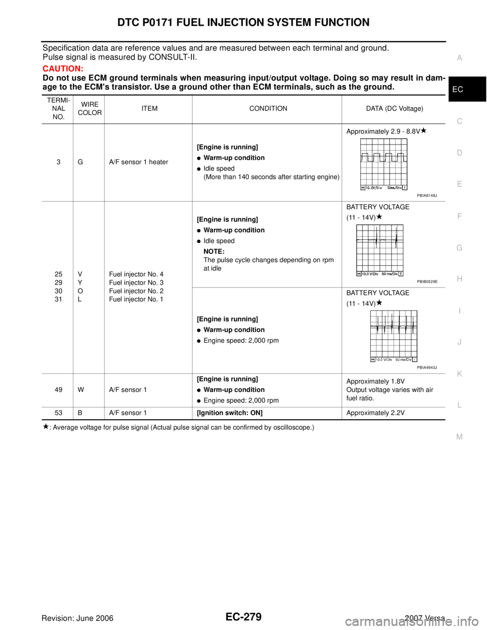
DTC P0171 FUEL INJECTION SYSTEM FUNCTION
EC-279
C
D
E
F
G
H
I
J
K
L
MA
EC
Revision: June 20062007 Versa
Specification data are reference values and are measured between each terminal and ground.
Pulse signal is measured by CONSULT-II.
CAUTION:
Do not use ECM ground terminals when measuring input/output voltage. Doing so may result in dam-
age to the ECM's transistor. Use a ground other than ECM terminals, such as the ground.
: Average voltage for pulse signal (Actual pulse signal can be confirmed by oscilloscope.) TERMI-
NAL
NO.WIRE
COLORITEM CONDITION DATA (DC Voltage)
3 G A/F sensor 1 heater[Engine is running]
�Warm-up condition
�Idle speed
(More than 140 seconds after starting engine)Approximately 2.9 - 8.8V
25
29
30
31V
Y
O
LFuel injector No. 4
Fuel injector No. 3
Fuel injector No. 2
Fuel injector No. 1[Engine is running]
�Warm-up condition
�Idle speed
NOTE:
The pulse cycle changes depending on rpm
at idleBATTERY VOLTAGE
(11 - 14V)
[Engine is running]
�Warm-up condition
�Engine speed: 2,000 rpmBATTERY VOLTAGE
(11 - 14V)
49 W A/F sensor 1[Engine is running]
�Warm-up condition
�Engine speed: 2,000 rpmApproximately 1.8V
Output voltage varies with air
fuel ratio.
53 B A/F sensor 1[Ignition switch: ON]Approximately 2.2V
PBIA8148J
PBIB0529E
PBIA4943J
Page 1456 of 2896
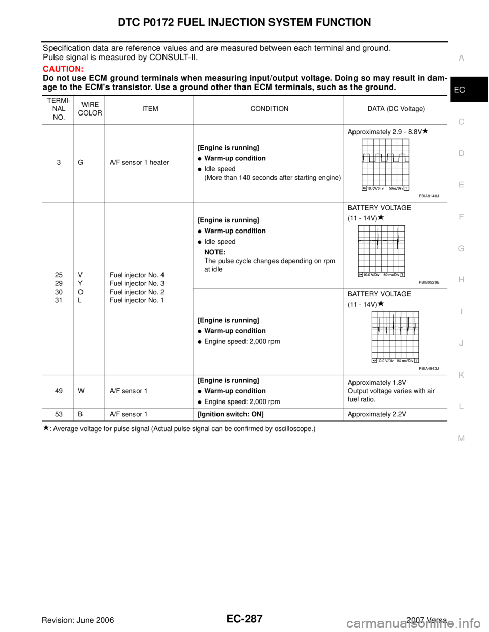
DTC P0172 FUEL INJECTION SYSTEM FUNCTION
EC-287
C
D
E
F
G
H
I
J
K
L
MA
EC
Revision: June 20062007 Versa
Specification data are reference values and are measured between each terminal and ground.
Pulse signal is measured by CONSULT-II.
CAUTION:
Do not use ECM ground terminals when measuring input/output voltage. Doing so may result in dam-
age to the ECM's transistor. Use a ground other than ECM terminals, such as the ground.
: Average voltage for pulse signal (Actual pulse signal can be confirmed by oscilloscope.) TERMI-
NAL
NO.WIRE
COLORITEM CONDITION DATA (DC Voltage)
3 G A/F sensor 1 heater[Engine is running]
�Warm-up condition
�Idle speed
(More than 140 seconds after starting engine)Approximately 2.9 - 8.8V
25
29
30
31V
Y
O
LFuel injector No. 4
Fuel injector No. 3
Fuel injector No. 2
Fuel injector No. 1[Engine is running]
�Warm-up condition
�Idle speed
NOTE:
The pulse cycle changes depending on rpm
at idleBATTERY VOLTAGE
(11 - 14V)
[Engine is running]
�Warm-up condition
�Engine speed: 2,000 rpmBATTERY VOLTAGE
(11 - 14V)
49 W A/F sensor 1[Engine is running]
�Warm-up condition
�Engine speed: 2,000 rpmApproximately 1.8V
Output voltage varies with air
fuel ratio.
53 B A/F sensor 1[Ignition switch: ON]Approximately 2.2V
PBIA8148J
PBIB0529E
PBIA4943J
Page 1472 of 2896
DTC P0222, P0223 TP SENSOR
EC-303
C
D
E
F
G
H
I
J
K
L
MA
EC
Revision: June 20062007 Versa
DTC Confirmation ProcedureUBS00QGU
NOTE:
If DTC Confirmation Procedure has been previously conducted, always turn ignition switch OFF and wait at
least 10 seconds before conducting the next test.
TESTING CONDITION:
Before performing the following procedure, confirm that battery voltage is more than 10V at idle.
WITH CONSULT-II
1. Turn ignition switch ON.
2. Select “DATA MONITOR” mode with CONSULT-II.
3. Start engine and let it idle for 1 second.
4. If DTC is detected, go to EC-305, "
Diagnostic Procedure" .
WITH GST
Follow the procedure “WITH CONSULT-II” above.
SEF 0 58 Y