2007 NISSAN LATIO trunk
[x] Cancel search: trunkPage 2101 of 2896
IP-1
INSTRUMENT PANEL
I BODY
CONTENTS
C
D
E
F
G
H
J
K
L
M
SECTION IP
A
B
IP
Revision: June 20062007 Versa PRECAUTIONS .......................................................... 2
Precautions for Supplemental Restraint System
(SRS) “AIR BAG” and “SEAT BELT PRE-TEN-
SIONER” .................................................................. 2
Precautions .............................................................. 2
PREPARATION ........................................................... 3
Special Service Tools ............................................... 3
Commercial Service Tools ........................................ 3
SQUEAK AND RATTLE TROUBLE DIAGNOSES ..... 4
Work Flow ................................................................ 4
CUSTOMER INTERVIEW ..................................... 4
DUPLICATE THE NOISE AND TEST DRIVE ....... 5
CHECK RELATED SERVICE BULLETINS ........... 5
LOCATE THE NOISE AND IDENTIFY THE
ROOT CAUSE ...................................................... 5
REPAIR THE CAUSE ........................................... 5
CONFIRM THE REPAIR ....................................... 6
Generic Squeak and Rattle Troubleshooting ........... 6
INSTRUMENT PANEL .......................................... 6
CENTER CONSOLE ............................................. 6
DOORS ................................................................. 6TRUNK .................................................................. 7
SUNROOF/HEADLINING ..................................... 7
OVERHEAD CONSOLE (FRONT AND REAR) ..... 7
SEATS ................................................................... 7
UNDERHOOD ....................................................... 7
Diagnostic Worksheet ............................................... 8
INSTRUMENT PANEL ASSEMBLY ......................... 10
Component Parts .................................................... 10
Removal and Installation ........................................ 11
WORK STEPS .................................................... 11
INSTRUMENT PANEL ASSEMBLY .................... 12
CLUSTER LID A .................................................. 16
CLUSTER LID C ................................................. 18
COMBINATION METER ...................................... 19
GLOVE BOX ASSEMBLY ................................... 21
INSTRUMENT LOWER FINISHER ..................... 21
CENTER CONSOLE ASSEMBLY ....................... 22
Disassembly and Assembly .................................... 24
GLOVE BOX ASSEMBLY ................................... 24
CENTER CONSOLE ASSEMBLY ....................... 25
COMBINATION METER ...................................... 25
Page 2107 of 2896
SQUEAK AND RATTLE TROUBLE DIAGNOSES
IP-7
C
D
E
F
G
H
J
K
L
MA
B
IP
Revision: June 20062007 Versa
Tapping or moving the components or pressing on them while driving to duplicate the conditions can isolate
many of these incidents. You can usually insulate the areas with felt cloth tape or insulator foam blocks from
the NISSAN Squeak and Rattle Kit (J-43980) to repair the noise.
TRUNK
Trunk noises are often caused by a loose jack or loose items put into the trunk by the owner.
In addition look for:
1. Trunk lid bumpers out of adjustment
2. Trunk lid striker out of adjustment
3. The trunk lid torsion bars knocking together
4. A loose license plate or bracket
Most of these incidents can be repaired by adjusting, securing or insulating the item(s) or component(s) caus-
ing the noise.
SUNROOF/HEADLINING
Noises in the sunroof/headlining area can often be traced to one of the following:
1. Sunroof lid, rail, linkage or seals making a rattle or light knocking noise
2. Sun visor shaft shaking in the holder
3. Front or rear windshield touching headliner and squeaking
Again, pressing on the components to stop the noise while duplicating the conditions can isolate most of these
incidents. Repairs usually consist of insulating with felt cloth tape.
OVERHEAD CONSOLE (FRONT AND REAR)
Overhead console noises are often caused by the console panel clips not being engaged correctly. Most of
these incidents are repaired by pushing up on the console at the clip locations until the clips engage.
In addition look for:
1. Loose harness or harness connectors.
2. Front console map/reading lamp lens loose.
3. Loose screws at console attachment points.
SEATS
When isolating seat noise it's important to note the position the seat is in and the load placed on the seat when
the noise is present. These conditions should be duplicated when verifying and isolating the cause of the
noise.
Cause of seat noise include:
1. Headrest rods and holder
2. A squeak between the seat pad cushion and frame
3. The rear seatback lock and bracket
These noises can be isolated by moving or pressing on the suspected components while duplicating the con-
ditions under which the noise occurs. Most of these incidents can be repaired by repositioning the component
or applying urethane tape to the contact area.
UNDERHOOD
Some interior noise may be caused by components under the hood or on the engine wall. The noise is then
transmitted into the passenger compartment.
Causes of transmitted underhood noise include:
1. Any component mounted to the engine wall
2. Components that pass through the engine wall
3. Engine wall mounts and connectors
4. Loose radiator mounting pins
5. Hood bumpers out of adjustment
6. Hood striker out of adjustment
These noises can be difficult to isolate since they cannot be reached from the interior of the vehicle. The best
method is to secure, move or insulate one component at a time and test drive the vehicle. Also, engine RPM
or load can be changed to isolate the noise. Repairs can usually be made by moving, adjusting, securing, or
insulating the component causing the noise.
Page 2174 of 2896
![NISSAN LATIO 2007 Service Repair Manual LAN-48
[CAN]
TROUBLE DIAGNOSIS
Revision: June 20062007 Versa
CAN Communication Signal ChartUKS005VQ
Refer to LAN-15, "How to Use CAN Communication Signal Chart" for how to use CAN communication signa NISSAN LATIO 2007 Service Repair Manual LAN-48
[CAN]
TROUBLE DIAGNOSIS
Revision: June 20062007 Versa
CAN Communication Signal ChartUKS005VQ
Refer to LAN-15, "How to Use CAN Communication Signal Chart" for how to use CAN communication signa](/manual-img/5/57361/w960_57361-2173.png)
LAN-48
[CAN]
TROUBLE DIAGNOSIS
Revision: June 20062007 Versa
CAN Communication Signal ChartUKS005VQ
Refer to LAN-15, "How to Use CAN Communication Signal Chart" for how to use CAN communication signal
chart.
TYPE 1/TYPE 2/TYPE 3/TYPE 4
NOTE:
Refer to LAN-41, "
Abbreviation List" for the abbreviations of the connecting units.
T: Transmit R: Receive
Signals ECM BCM EPS
I-KEY
*1M&A
ABS*2IPDM-E
A/C compressor request signal
*3TR
ASCD CRUISE lamp signal T R
ASCD SET lamp signal T R
Cooling fan motor operation signal TR
Engine coolant temperature signal T R
Engine speed signal T R
Engine status signal T R
Fuel consumption monitor signal T R
Malfunction indicator lamp signal T R
A/C switch signal
*3RT
Blower fan motor switch signal R T
Buzzer output signalTR
TR
Day time running light request signal
*4TR
Door lock/unlock status signal T R
Door switch signal T R R R
Front wiper request signal T R
High beam request signal T R R
Horn chirp signal T R
Ignition switch signal T R
Low beam request signal T R
Position lights request signal T R R
Rear window defogger switch signal T R
Theft warning horn request signal T R
Tire pressure signal
*5TR
Trunk open/close status signal T R
Turn indicator signal T R
EPS operation signal R T
EPS warning lamp signal T R
Door lock/unlock/trunk open request signal R T
Hazard request signal R T
Ignition knob switch signal R T
KEY warning lamp signal T R
LOCK warning lamp signal T R
Panic alarm request signal R T
Fuel level sensor signal R T
Page 2177 of 2896
![NISSAN LATIO 2007 Service Repair Manual TROUBLE DIAGNOSIS
LAN-51
[CAN]
C
D
E
F
G
H
I
J
L
MA
B
LAN
Revision: June 20062007 Versa
Cooling fan motor operation signal TR
Engine coolant temperature signal T R
Engine speed signal T R R
Engine sta NISSAN LATIO 2007 Service Repair Manual TROUBLE DIAGNOSIS
LAN-51
[CAN]
C
D
E
F
G
H
I
J
L
MA
B
LAN
Revision: June 20062007 Versa
Cooling fan motor operation signal TR
Engine coolant temperature signal T R
Engine speed signal T R R
Engine sta](/manual-img/5/57361/w960_57361-2176.png)
TROUBLE DIAGNOSIS
LAN-51
[CAN]
C
D
E
F
G
H
I
J
L
MA
B
LAN
Revision: June 20062007 Versa
Cooling fan motor operation signal TR
Engine coolant temperature signal T R
Engine speed signal T R R
Engine status signal T R
Fuel consumption monitor signal T R
Malfunction indicator lamp signal T R
Wide open throttle position signal T R
A/C switch signal R T
Blower fan motor switch signal R T
Buzzer output signalTR
TR
Day time running light request signal
*3TRR
Door lock/unlock status signal T R
Door switch signal T R R R
Front wiper request signal T R
High beam request signal T R R
Horn chirp signal T R
Ignition switch signal T R
Low beam request signal T R
Position lights request signal T R R
Rear window defogger switch signal T R
Theft warning horn request signal T R
Tire pressure signal
*4
Trunk open/close status signal T R
Turn indicator signal T R
EPS operation signal R T
EPS warning lamp signal T R
Door lock/unlock/trunk open request signal R T
Hazard request signal R T
Ignition knob switch signal R T
KEY warning lamp signal T R
LOCK warning lamp signal T R
Panic alarm request signal R T
Fuel level sensor signal R T
Sleep/wake up signalRT
TRR R
Overdrive control switch signal T R
Stop lamp switch signal T R
Vehicle speed signalRRR T
RRRTR
R
*5R*5T*5
ABS warning lamp signal R T
Brake warning lamp signal R T
CVT self-diagnosis signal R TSignals ECM BCM EPS
I-KEY
*1M&A
ABS*2TCM IPDM-E
Page 2339 of 2896
GENERAL MAINTENANCE
MA-5
C
D
E
F
G
H
I
J
K
MA
B
MA
Revision: June 20062007 Versa
GENERAL MAINTENANCEPFP:00000
Explanation of General MaintenanceELS001YB
General MaintenanceELS001YC
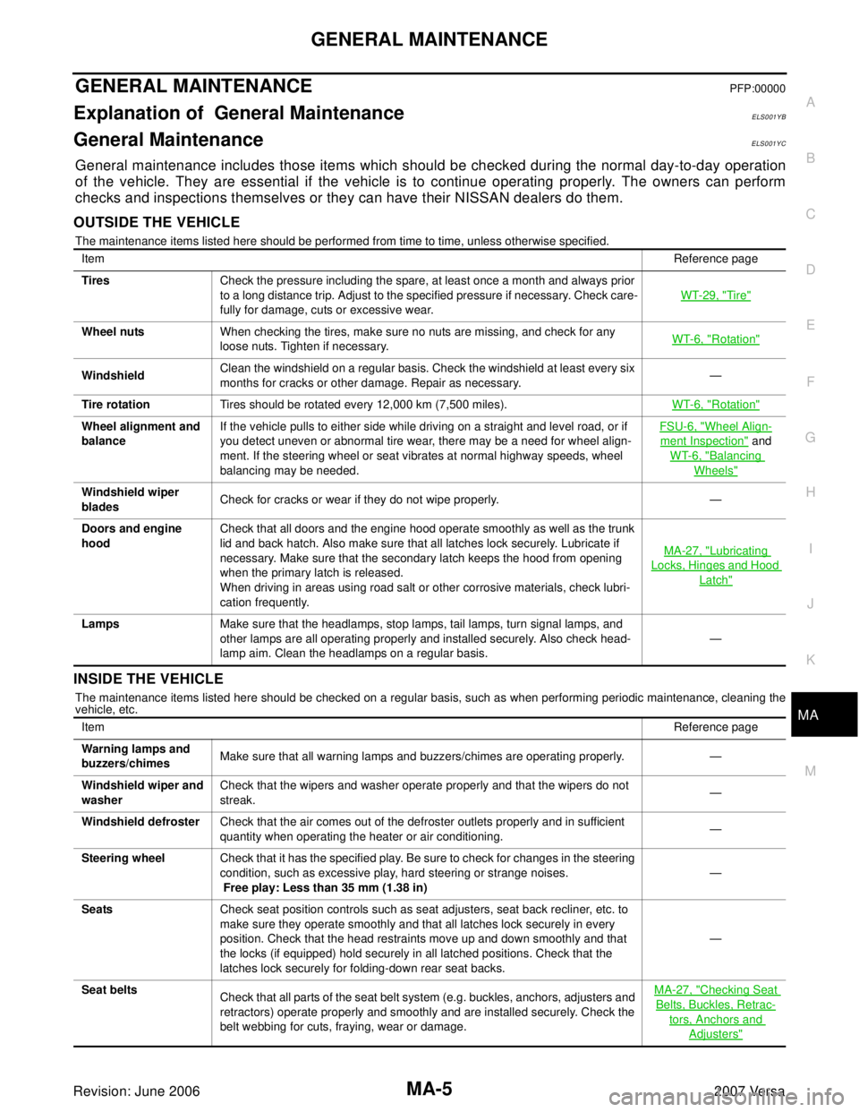
General maintenance includes those items which should be checked during the normal day-to-day operation
of the vehicle. They are essential if the vehicle is to continue operating properly. The owners can perform
checks and inspections themselves or they can have their NISSAN dealers do them.
OUTSIDE THE VEHICLE
The maintenance items listed here should be performed from time to time, unless otherwise specified.
INSIDE THE VEHICLE
The maintenance items listed here should be checked on a regular basis, such as when performing periodic maintenance, cleaning the
vehicle, etc.ItemReference page
TiresCheck the pressure including the spare, at least once a month and always prior
to a long distance trip. Adjust to the specified pressure if necessary. Check care-
fully for damage, cuts or excessive wear.WT-29, "
Tire"
Wheel nutsWhen checking the tires, make sure no nuts are missing, and check for any
loose nuts. Tighten if necessary.WT-6, "Rotation"
WindshieldClean the windshield on a regular basis. Check the windshield at least every six
months for cracks or other damage. Repair as necessary.—
Tire rotationTires should be rotated every 12,000 km (7,500 miles).WT-6, "
Rotation"
Wheel alignment and
balanceIf the vehicle pulls to either side while driving on a straight and level road, or if
you detect uneven or abnormal tire wear, there may be a need for wheel align-
ment. If the steering wheel or seat vibrates at normal highway speeds, wheel
balancing may be needed.FSU-6, "Wheel Align-
ment Inspection" and
WT-6, "
Balancing
Wheels"
Windshield wiper
bladesCheck for cracks or wear if they do not wipe properly. —
Doors and engine
hoodCheck that all doors and the engine hood operate smoothly as well as the trunk
lid and back hatch. Also make sure that all latches lock securely. Lubricate if
necessary. Make sure that the secondary latch keeps the hood from opening
when the primary latch is released.
When driving in areas using road salt or other corrosive materials, check lubri-
cation frequently.MA-27, "
Lubricating
Locks, Hinges and Hood
Latch"
LampsMake sure that the headlamps, stop lamps, tail lamps, turn signal lamps, and
other lamps are all operating properly and installed securely. Also check head-
lamp aim. Clean the headlamps on a regular basis.—
ItemReference page
Warning lamps and
buzzers/chimesMake sure that all warning lamps and buzzers/chimes are operating properly. —
Windshield wiper and
washerCheck that the wipers and washer operate properly and that the wipers do not
streak.—
Windshield defrosterCheck that the air comes out of the defroster outlets properly and in sufficient
quantity when operating the heater or air conditioning.—
Steering wheelCheck that it has the specified play. Be sure to check for changes in the steering
condition, such as excessive play, hard steering or strange noises.
Free play: Less than 35 mm (1.38 in)—
SeatsCheck seat position controls such as seat adjusters, seat back recliner, etc. to
make sure they operate smoothly and that all latches lock securely in every
position. Check that the head restraints move up and down smoothly and that
the locks (if equipped) hold securely in all latched positions. Check that the
latches lock securely for folding-down rear seat backs.—
Seat belts
Check that all parts of the seat belt system (e.g. buckles, anchors, adjusters and
retractors) operate properly and smoothly and are installed securely. Check the
belt webbing for cuts, fraying, wear or damage.MA-27, "
Checking Seat
Belts, Buckles, Retrac-
tors, Anchors and
Adjusters"
Page 2578 of 2896

PG-62
HARNESS
Revision: June 20062007 Versa
IGNSYS EC Ignition System
I/KEY BL Intelligent Key System
ILL LT Illumination
INJECT EC Injector
INT/L LT Room/Map, Vanity and Luggage Lamps
IVC EC Intake Valve Timing Control Solenoid Valve
KEYLES BL Remote Keyless Entry System
KS EC Knock Sensor
LPSV AT Line Pressure Solenoid Valve
LPSV CVT Line Pressure Solenoid Valve
L/USSV CVT Lock-up Select Solenoid Valve
MAFS EC Mass Air Flow Sensor
MAIN AT Main Power Supply and Ground Circuit
MAIN EC Main Power Supply and Ground Circuit
METER DI Speedometer, Tachometer, Temp. and Fuel Gauges
MIL/DL EC Malfunction Indicator Lamp
MIRROR GW Door Mirror
NATS BL Nissan Anti-Theft System
NONDTC AT Non-detectable Item
NONDTC CVT Non-detectable Item
ODSW CVT Overdrive Control Switch
OVRCSV AT Over Run Clutch Solenoid Valve
P/SCKT WW Power Socket
PGC/V EC EVAP Canister Purge Volume Control Solenoid Valve
PHASE EC Camshaft Position Sensor (PHASE)
PNP/SW AT Park/Neutral Position Switch
PNP/SW CVT Park/Neutral Position Switch
PNP/SW EC Park/Neutral Position Switch
POS EC Crankshaft Position Sensor (POS)
POWER CVT Transmission Control Module (Power Supply)
PRE/SE EC EVAP Control System Pressure Sensor
PRIPS CVT Primary Pressure Sensor
PRSCVT CVT Primary Speed Sensor CVT (Revolution Sensor)
PT/SEN AT Powertrain Revolution Sensor
RP/SEN EC Refrigerant Pressure Sensor
SECPS CVT Secondary Pressure Sensor
SECPSV CVT Secondary Speed Sensor CVT (Revolution Sensor)
SEN/PW EC Sensor Power Supply
SESCVT CVT Secondary Pressure Sensor Solenoid Valve
SHIFT AT A/T Shift Lock System
SHIFT CVT CVT Shift Lock System
SROOF RF Sunroof
SRS SRS Supplemental Restraint System
SSV/A AT Shift Solenoid Valve A
SSV/B AT Shift Solenoid Valve B
START SC Starting System
STM CVT Step Motor
STSIG CVT Start Signal Circuit
STOP/L LT Stop Lamp
TCV AT Torque Converter Clutch Solenoid Valve
TCV CVT Torque Converter Clutch Solenoid Valve
T/LID BL Trunk Lid Opener
Page 2619 of 2896
RF-1
ROOF
I BODY
CONTENTS
C
D
E
F
G
H
J
K
L
M
SECTION RF
A
B
RF
Revision: June 20062007 Versa PRECAUTIONS .......................................................... 2
Precautions for Supplemental Restraint System
(SRS) “AIR BAG” and “SEAT BELT PRE-TEN-
SIONER” .................................................................. 2
Precautions .............................................................. 2
PREPARATION ........................................................... 3
Commercial Service Tools ........................................ 3
SQUEAK AND RATTLE TROUBLE DIAGNOSES ..... 4
Work Flow ................................................................ 4
CUSTOMER INTERVIEW ..................................... 4
DUPLICATE THE NOISE AND TEST DRIVE ....... 5
CHECK RELATED SERVICE BULLETINS ........... 5
LOCATE THE NOISE AND IDENTIFY THE
ROOT CAUSE ...................................................... 5
REPAIR THE CAUSE ........................................... 5
CONFIRM THE REPAIR ....................................... 6
Generic Squeak and Rattle Troubleshooting ........... 6
INSTRUMENT PANEL .......................................... 6
CENTER CONSOLE ............................................. 6
DOORS ................................................................. 6
TRUNK .................................................................. 7
SUNROOF/HEADLINING ..................................... 7
OVERHEAD CONSOLE (FRONT AND REAR) ..... 7
SEATS ................................................................... 7
UNDERHOOD ....................................................... 7
Diagnostic Worksheet .............................................. 8
SUNROOF ................................................................ 10
Component Parts and Harness Connector Location ... 10
System Description ................................................ 10
OUTLINE ............................................................. 10
OPERATION ....................................................... 10
CAN Communication System Description .............. 12Wiring Diagram — SROOF — ................................ 13
Terminals and Reference Values for BCM .............. 15
Terminals and Reference Values for Sunroof Motor
Assembly ................................................................ 15
Work Flow ............................................................... 15
CONSULT-II Function (BCM) ................................. 16
CONSULT-II START PROCEDURE .................... 16
Work Support .......................................................... 16
Active Test .............................................................. 16
Data Monitor ........................................................... 16
Trouble Diagnosis Chart by Symptom .................... 17
BCM Power Supply and Ground Circuit Check ...... 17
Sunroof Switch System Check ............................... 17
Sunroof Motor Assembly Power Supply and Ground
Circuit Check .......................................................... 19
Door Switch Check ................................................. 20
Removal and Installation ........................................ 22
SUNROOF UNIT ASSEMBLY ............................. 24
GLASS LID .......................................................... 25
SUNSHADE ........................................................ 26
WIND DEFLECTOR ............................................ 26
SUNROOF MOTOR ASSEMBLY ........................ 26
LINK ASSEMBLY ................................................ 27
Fitting Adjustment ................................................... 28
GAP ADJUSTMENT ............................................ 28
HEIGHT ADJUSTMENT ...................................... 28
Inspection ............................................................... 29
WIND DEFLECTOR ............................................ 29
LINK ASSEMBLY AND WIRE ............................. 29
WEATHERSTRIP ................................................ 29
DRAIN HOSES .................................................... 30
Page 2625 of 2896
SQUEAK AND RATTLE TROUBLE DIAGNOSES
RF-7
C
D
E
F
G
H
J
K
L
MA
B
RF
Revision: June 20062007 Versa
TRUNK
Trunk noises are often caused by a loose jack or loose items put into the trunk by the owner.
In addition look for:
1. Trunk lid bumpers out of adjustment
2. Trunk lid striker out of adjustment
3. The trunk lid torsion bars knocking together
4. A loose license plate or bracket
Most of these incidents can be repaired by adjusting, securing or insulating the item(s) or component(s) caus-
ing the noise.
SUNROOF/HEADLINING
Noises in the sunroof/headlining area can often be traced to one of the following:
1. Sunroof lid, rail, linkage or seals making a rattle or light knocking noise
2. Sun visor shaft shaking in the holder
3. Front or rear windshield touching headliner and squeaking
Again, pressing on the components to stop the noise while duplicating the conditions can isolate most of these
incidents. Repairs usually consist of insulating with felt cloth tape.
OVERHEAD CONSOLE (FRONT AND REAR)
Overhead console noises are often caused by the console panel clips not being engaged correctly. Most of
these incidents are repaired by pushing up on the console at the clip locations until the clips engage.
In addition look for:
1. Loose harness or harness connectors.
2. Front console map/reading lamp lens loose.
3. Loose screws at console attachment points.
SEATS
When isolating seat noise it's important to note the position the seat is in and the load placed on the seat when
the noise is present. These conditions should be duplicated when verifying and isolating the cause of the
noise.
Cause of seat noise include:
1. Headrest rods and holder
2. A squeak between the seat pad cushion and frame
3. The rear seatback lock and bracket
These noises can be isolated by moving or pressing on the suspected components while duplicating the con-
ditions under which the noise occurs. Most of these incidents can be repaired by repositioning the component
or applying urethane tape to the contact area.
UNDERHOOD
Some interior noise may be caused by components under the hood or on the engine wall. The noise is then
transmitted into the passenger compartment.
Causes of transmitted underhood noise include:
1. Any component installed on the engine wall
2. Components that pass through the engine wall
3. Engine wall mounts and connectors
4. Loose radiator pins
5. Hood bumpers out of adjustment
6. Hood striker out of adjustment
These noises can be difficult to isolate since they cannot be reached from the interior of the vehicle. The best
method is to secure, move or insulate one component at a time and test drive the vehicle. Also, engine RPM
or load can be changed to isolate the noise. Repairs can usually be made by moving, adjusting, securing, or
insulating the component causing the noise.