Page 1105 of 2896

CVT-208
TRANSAXLE ASSEMBLY
Revision: June 20062007 Versa
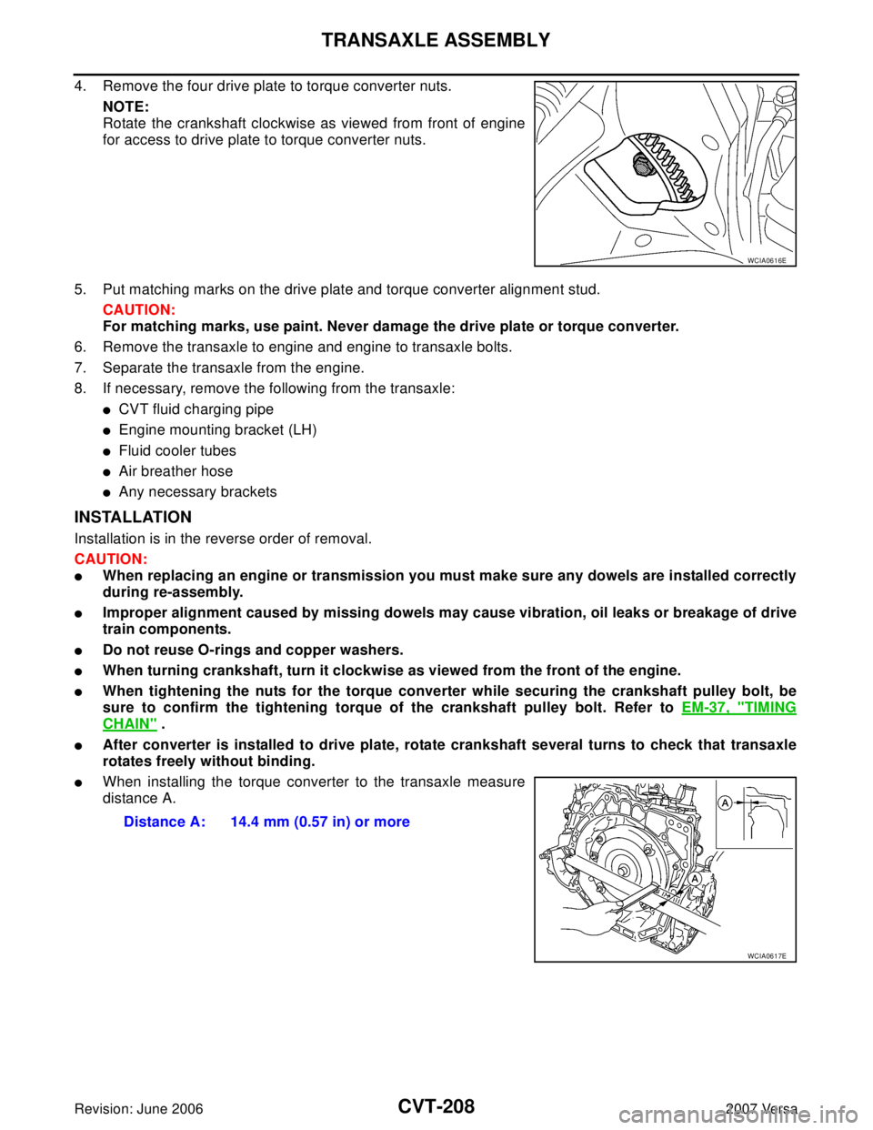
4. Remove the four drive plate to torque converter nuts.
NOTE:
Rotate the crankshaft clockwise as viewed from front of engine
for access to drive plate to torque converter nuts.
5. Put matching marks on the drive plate and torque converter alignment stud.
CAUTION:
For matching marks, use paint. Never damage the drive plate or torque converter.
6. Remove the transaxle to engine and engine to transaxle bolts.
7. Separate the transaxle from the engine.
8. If necessary, remove the following from the transaxle:
�CVT fluid charging pipe
�Engine mounting bracket (LH)
�Fluid cooler tubes
�Air breather hose
�Any necessary brackets
INSTALLATION
Installation is in the reverse order of removal.
CAUTION:
�When replacing an engine or transmission you must make sure any dowels are installed correctly
during re-assembly.
�Improper alignment caused by missing dowels may cause vibration, oil leaks or breakage of drive
train components.
�Do not reuse O-rings and copper washers.
�When turning crankshaft, turn it clockwise as viewed from the front of the engine.
�When tightening the nuts for the torque converter while securing the crankshaft pulley bolt, be
sure to confirm the tightening torque of the crankshaft pulley bolt. Refer to EM-37, "
TIMING
CHAIN" .
�After converter is installed to drive plate, rotate crankshaft several turns to check that transaxle
rotates freely without binding.
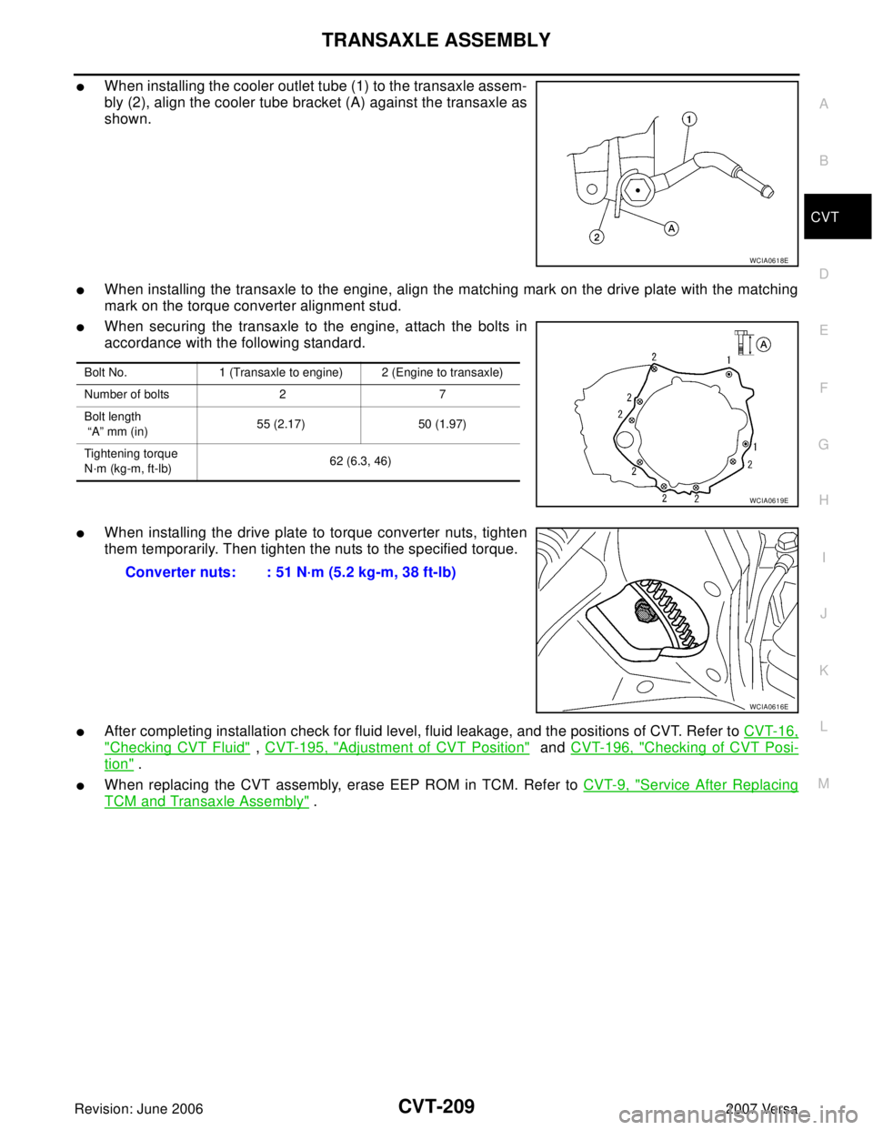
�When installing the torque converter to the transaxle measure
distance A.
WCIA0616E
Distance A: 14.4 mm (0.57 in) or more
WCIA0617E
Page 1106 of 2896

TRANSAXLE ASSEMBLY
CVT-209
D
E
F
G
H
I
J
K
L
MA
B
CVT
Revision: June 20062007 Versa
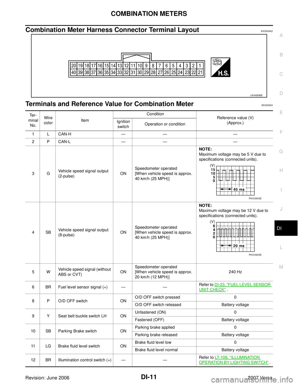
�When installing the cooler outlet tube (1) to the transaxle assem-
bly (2), align the cooler tube bracket (A) against the transaxle as
shown.
�When installing the transaxle to the engine, align the matching mark on the drive plate with the matching
mark on the torque converter alignment stud.
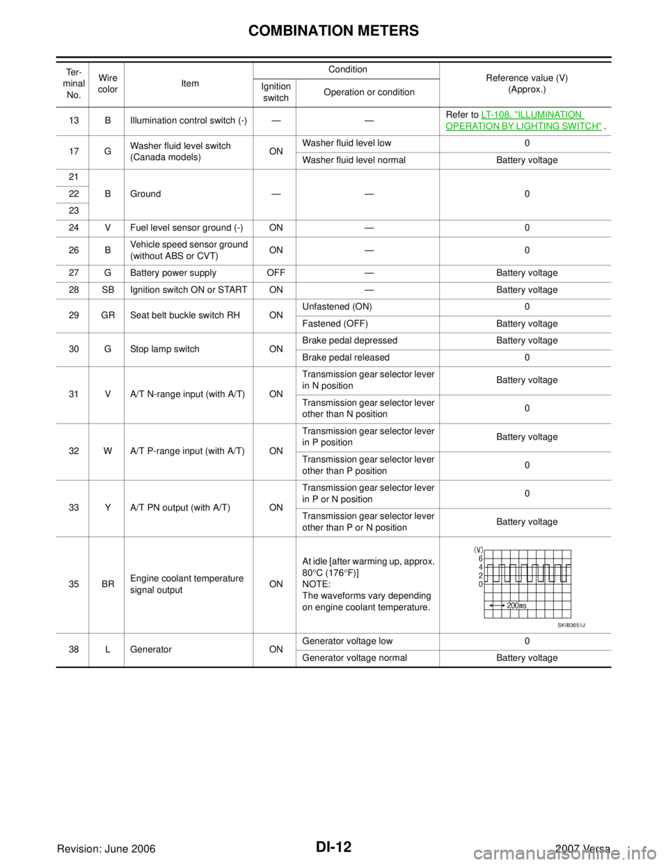
�When securing the transaxle to the engine, attach the bolts in
accordance with the following standard.
�When installing the drive plate to torque converter nuts, tighten
them temporarily. Then tighten the nuts to the specified torque.
�After completing installation check for fluid level, fluid leakage, and the positions of CVT. Refer to CVT-16,
"Checking CVT Fluid" , CVT-195, "Adjustment of CVT Position" and CVT-196, "Checking of CVT Posi-
tion" .
�When replacing the CVT assembly, erase EEP ROM in TCM. Refer to CVT-9, "Service After Replacing
TCM and Transaxle Assembly" .
WCIA0618E
Bolt No. 1 (Transaxle to engine) 2 (Engine to transaxle)
Number of bolts 2 7
Bolt length
“A” mm (in)55 (2.17) 50 (1.97)
Tightening torque
N·m (kg-m, ft-lb)62 (6.3, 46)
WCIA0619E
Converter nuts: : 51 N·m (5.2 kg-m, 38 ft-lb)
WCIA0616E
Page 1107 of 2896

CVT-210
SERVICE DATA AND SPECIFICATIONS (SDS)
Revision: June 20062007 Versa
SERVICE DATA AND SPECIFICATIONS (SDS)PFP:00030
General SpecificationsUCS0064W
*1: Refer to MA-11, "Fluids and Lubricants" .
Vehicle Speed When Shifting GearsUCS0064X
Numerical value data are reference values.
CAUTION:
Lock-up clutch is engaged when vehicle speed is approximately 18 km/h (11 MPH) to 90 km/h (56 MPH).
Stall SpeedUCS0064Y
Line PressureUCS0064Z
*: Reference values
Solenoid ValvesUCS00650
Applied model MR18DE engine
CVT modelRE0F08A
CVT assembly Model code number 1XB6B
Transmission gear ratio“D” position Variable
Reverse 2.689
Final drive 5.473
Recommended fluid NISSAN CVT Fluid NS-2*1
Fluid capacity 8.3 liter (8-3/4 US qt, 7-1/4 Imp qt)
CAUTION:
�Use only Genuine NISSAN CVT Fluid NS-2. Do not mix with other fluid.
�Using CVT fluid other than Genuine NISSAN CVT Fluid NS-2 will deteriorate in driveability and CVT durability, and may
damage the CVT, which is not covered by the warranty.
Engine type Throttle position Shift patternEngine speed (rpm)
At 40 km/h (25 MPH) At 60 km/h (37 MPH)
MR18DE8/8“D” position
Overdrive-off mode
“L” position 3,600 - 4,400 4,400 - 5,200
2/8“D” position 1,400 - 2,400 1,500 - 2,500
Overdrive-off mode 2,200 - 3,000 2,800 - 3,600
“L” position 3,200 - 4,000 3,900 - 4,700
Stall speed 2,300 - 3,200 rpm
Engine speed Line pressure kPa (kg/cm
2 , psi)
“R”, “D” and “L” positions
At idle 650 (6.63, 94.3)
At stall 4,250 (43.35, 616.3)*
Name Resistance (Approx.) Terminal
Pressure control solenoid valve B (secondary
pressure solenoid valve)
2.5 - 5.0 Ω3
Pressure control solenoid valve A (line pressure
solenoid valve)2
Torque converter clutch solenoid valve
5 - 20 Ω12
Lock-up select solenoid valve13
Page 1108 of 2896
SERVICE DATA AND SPECIFICATIONS (SDS)
CVT-211
D
E
F
G
H
I
J
K
L
MA
B
CVT
Revision: June 20062007 Versa
CVT Fluid Temperature SensorUCS00651
Primary Speed SensorUCS00652
Secondary Speed SensorUCS00653
Removal and InstallationUCS00654
Name Condition CONSULT-II “DATA MONITOR” (Approx.) Resistance (Approx.)
AT F T E M P S E N20°C (68°F) 2.0 V 6.5 kΩ
80°C (176°F) 1.0 V 0.9 kΩ
Name Condition Data (Approx.)
Primary speed sensor When driving [“L” position, 20 km/h (12 MPH)]. 1000 Hz
Name Condition Data (Approx.)
Secondary speed sensor When driving [“D” position, 20 km/h (12 MPH)]. 570 Hz
Distance between end of converter housing and torque converter 14.4 mm (0.57 in) or more
Page 1120 of 2896

COMBINATION METERS
DI-11
C
D
E
F
G
H
I
J
L
MA
B
DI
Revision: June 20062007 Versa
Combination Meter Harness Connector Terminal LayoutEKS00IAQ
Terminals and Reference Value for Combination MeterEKS00I0A
LKIA0698E
Te r -
minal
No.Wire
colorItemCondition
Reference value (V)
(Approx.) Ignition
switchOperation or condition
1 L CAN-H — — —
2 P CAN-L — — —
3GVehicle speed signal output
(2-pulse)ONSpeedometer operated
[When vehicle speed is approx.
40 km/h (25 MPH)] NOTE:
Maximum voltage may be 5 V due to
specifications (connected units).
4SBVehicle speed signal output
(8-pulse)ONSpeedometer operated
[When vehicle speed is approx.
40 km/h (25 MPH)]NOTE:
Maximum voltage may be 12 V due to
specifications (connected units).
5WVehicle speed signal (without
ABS or CVT)ONSpeedometer operated
[When vehicle speed is approx.
20 km/h (12 MPH)]240 Hz
6 BR Fuel level sensor signal (+) — —Refer to DI-23, "
FUEL LEVEL SENSOR
UNIT CHECK" .
8 P O/D OFF switch ONO/D OFF switch pressed 0
O/D OFF switch released Battery voltage
9 Y Seat belt buckle switch LH ONUnfastened (ON) 0
Fastened (OFF) Battery voltage
10 SB Parking Brake switch ONParking brake applied 0
Parking brake released Battery voltage
11 LG Brake fluid level switch ONBrake fluid level low 0
Brake fluid level normal Battery voltage
12 BR Illumination control switch (+) — —Refer to LT-108, "
ILLUMINATION
OPERATION BY LIGHTING SWITCH" .
PKIC0642E
PKIC0643E
Page 1121 of 2896

DI-12
COMBINATION METERS
Revision: June 20062007 Versa
13 B Illumination control switch (-) — —Refer to LT-108, "ILLUMINATION
OPERATION BY LIGHTING SWITCH" .
17 GWasher fluid level switch
(Canada models)ONWasher fluid level low 0
Washer fluid level normal Battery voltage
21
BGround — — 0 22
23
24 V Fuel level sensor ground (-) ON — 0
26 BVehicle speed sensor ground
(without ABS or CVT)ON — 0
27 G Battery power supply OFF — Battery voltage
28 SB Ignition switch ON or START ON — Battery voltage
29 GR Seat belt buckle switch RH ONUnfastened (ON) 0
Fastened (OFF) Battery voltage
30 G Stop lamp switch ONBrake pedal depressed Battery voltage
Brake pedal released 0
31 V A/T N-range input (with A/T) ONTransmission gear selector lever
in N positionBattery voltage
Transmission gear selector lever
other than N position0
32 W A/T P-range input (with A/T) ONTransmission gear selector lever
in P positionBattery voltage
Transmission gear selector lever
other than P position0
33 Y A/T PN output (with A/T) ONTransmission gear selector lever
in P or N position0
Transmission gear selector lever
other than P or N positionBattery voltage
35 BREngine coolant temperature
signal outputONAt idle [after warming up, approx.
80°C (176°F)]
NOTE:
The waveforms vary depending
on engine coolant temperature.
38 L Generator ONGenerator voltage low 0
Generator voltage normal Battery voltage Te r -
minal
No.Wire
colorItemCondition
Reference value (V)
(Approx.) Ignition
switchOperation or condition
SKIB3651J
Page 1125 of 2896
DI-16
COMBINATION METERS
Revision: June 20062007 Versa
NOTE:
Some items are not available due to vehicle specification.
*: The monitor will indicate “OFF” even though the brake warning lamp is on if either of the following conditions exist.
�The parking brake is engaged
�The brake fluid level is low e-4WD W/L [ON/OFF] X This item is not used for this model. “OFF” is always displayed.
EPS W/L [ON/OFF] X Indicates [ON/OFF] condition of EPS warning lamp.Display item [Unit]MAIN
SIGNALSSELECTION
FROM MENUContents
Page 1247 of 2896

EC-78Revision: June 2006
BASIC SERVICE PROCEDURE
2007 Versa
Throttle Valve Closed Position LearningUBS00QO9
DESCRIPTION
Throttle Valve Closed Position Learning is an operation to learn the fully closed position of the throttle valve by
monitoring the throttle position sensor output signal. It must be performed each time harness connector of
electric throttle control actuator or ECM is disconnected.
OPERATION PROCEDURE
1. Make sure that accelerator pedal is fully released.
2. Turn ignition switch ON.
3. Turn ignition switch OFF and wait at least 10 seconds.
Make sure that throttle valve moves during above 10 seconds by confirming the operating sound.
Idle Air Volume LearningUBS00QOA
DESCRIPTION
Idle Air Volume Learning is an operation to learn the idle air volume that keeps each engine within the specific
range. It must be performed under any of the following conditions:
�Each time electric throttle control actuator or ECM is replaced.
�Idle speed or ignition timing is out of specification.
PREPARATION
Before performing Idle Air Volume Learning, make sure that all of the following conditions are satisfied.
Learning will be cancelled if any of the following conditions are missed for even a moment.
�Battery voltage: More than 12.9V (At idle)
�Engine coolant temperature: 70 - 95°C (158 - 203°F)
�Park/neutral position (PNP) switch: ON
�Electric load switch: OFF
[Air conditioner (models with A/C), headlamp, rear window defogger]
On vehicles equipped with daytime light systems, if the parking brake is applied before the engine
is started the headlamp will not be illuminated.
�Steering wheel: Neutral (Straight-ahead position)
�Vehicle speed: Stopped
�Transmission: Warmed-up
–Models with CONSULT-II (A/T and CVT models)
Drive vehicle until “FLUID TEMP SE” in “DATA MONITOR” mode of “A/T” or “CVT” system indicates less
than 0.9V.
–Models without CONSULT-II (A/T and CVT models) and M/T models
Drive vehicle for 10 minutes.