Page 1149 of 2896

DI-40
A/T INDICATOR
Revision: June 20062007 Versa
A/T Indicator Does Not IlluminateEKS00I0Y
1. CHECK SEGMENT OF A/T INDICATOR
Perform self-diagnosis of combination meter. Refer to DI-13, "
OPER-
ATION PROCEDURE" .
Are all segments displayed?
YES >> GO TO 2.
NO >> Replace combination meter. Refer to IP-19, "
COMBINA-
TION METER" .
2. CHECK COMBINATION METER (CONSULT-II)
1. Connect CONSULT-II.
2. Select “METER” on CONSULT-II, and perform self-diagnosis of
combination meter. Refer to DI-14, "
SELF-DIAGNOSTIC
RESULTS" .
Self
-diagnostic results content
No malfunction detected>> GO TO 3.
Malfunction detected>> Check applicable parts, and repair or
replace as necessary.
3. CHECK COMBINATION METER INPUT SIGNAL
Use “DATA MONITOR” of “METER” on CONSULT-II. Confirm each
indication on the monitor when operating the A/T selector lever.
OK or NG
OK >> Replace combination meter. Refer to IP-19, "COMBINATION METER" .
NG >> GO TO 4.
SKIB1206J
SKIA4956E
CONSULT-II display Switch operation Operation status
P RANGE INDP range position ON
Except for P range position OFF
R RANGE INDR range position ON
Except for R range position OFF
N RANGE INDN range position ON
Except for N range position OFF
D RANGE INDD range position ON
Except for D range position OFF
2 RANGE IND2 range position ON
Except for 2 range position OFF
1 RANGE IND1 range position ON
Except for 1 range position OFF
PKIC0920E
Page 1154 of 2896

CVT INDICATOR
DI-45
C
D
E
F
G
H
I
J
L
MA
B
DI
Revision: June 20062007 Versa
CVT Indicator Does Not IlluminateEKS00I8E
1. CHECK SEGMENT OF CVT INDICATOR
Perform self-diagnosis of combination meter. Refer to DI-13, "
OPER-
ATION PROCEDURE" .
Are all segments displayed?
YES >> GO TO 2.
NO >> Replace combination meter. Refer to IP-19, "
COMBINA-
TION METER" .
2. CHECK COMBINATION METER (CONSULT-II)
1. Connect CONSULT-II.
2. Select “METER” on CONSULT-II, and perform self-diagnosis of
combination meter. Refer to DI-14, "
SELF-DIAGNOSTIC
RESULTS" .
Self
-diagnostic results content
No malfunction detected>> GO TO 3.
Malfunction detected>> Check applicable parts, and repair or
replace as necessary.
3. CHECK COMBINATION METER INPUT SIGNAL
Use “DATA MONITOR” of “METER” on CONSULT-II. Confirm each
indication on the monitor when operating the CVT selector lever.
OK or NG
OK >> Replace combination meter. Refer to IP-19, "COMBINATION METER" .
NG >> GO TO 4.
SKIB1206J
SKIA4956E
CONSULT-II display Switch operation Operation status
P RANGE INDP range position ON
Except for P range position OFF
R RANGE INDR range position ON
Except for R range position OFF
N RANGE INDN range position ON
Except for N range position OFF
D RANGE INDD range position ON
Except for D range position OFF
L RANGE INDL range position ON
Except for L range position OFF
WKIA5461E
Page 1161 of 2896
EKS00I13
CONSULT-I")
DI-52
WARNING CHIME
Revision: June 20062007 Versa
Terminals and Reference Values for BCMEKS00I12
Refer to BCS-12, "Terminals and Reference Values for BCM" .
CONSULT-II Function (BCM)EKS00I13
CONSULT-II can display each diagnostic item using the diagnostic test modes shown following.
CONSULT-II START PROCEDURE
Refer to GI-38, "CONSULT-II Start Procedure" .
DATA MONITOR
Display Item List
ACTIVE TEST
Display Item List
SELF-DIAG RESULTS
Display Item List
NOTE:
If “CAN communication [U1000]” is indicated, after printing the monitor item, go to “LAN system”. Refer to
LAN-44, "
TROUBLE DIAGNOSIS" .
BCM diagnostic
test itemDiagnostic mode Description
Inspection by partWORK SUPPORTSupports inspections and adjustments. Commands are transmitted to the BCM
for setting the status suitable for required operation, input/output signals are
received from the BCM and received data is displayed.
DATA MONITOR Displays BCM input/output data in real time.
ACTIVE TEST Operation of electrical loads can be checked by sending drive signal to them.
SELF-DIAG RESULTS Displays BCM self-diagnosis results.
CAN DIAG SUPPORT MNTR The result of transmit/receive diagnosis of CAN communication can be read.
ECU PART NUMBER BCM part number can be read.
CONFIGURATION Performs BCM configuration read/write functions.
Monitored item ALL SIGNALSSELECTION
FROM MENUContents
IGN ON SW X X Indicates [ON/OFF] condition of ignition switch.
KEY ON SW X X Indicates [ON/OFF] condition of key switch.
DOOR SW-DR X X Indicates [ON/OFF] condition of front door switch LH.
LIGHT SW 1ST X X Indicates [ON/OFF] condition of lighting switch.
BUCKLE SW X X Indicates [ON/OFF] condition of seat belt buckle switch LH.
Test item Malfunction is detected when···
IGN KEY WARN ALM This test is able to check key warning chime operation.
LIGHT WARN ALM This test is able to check light warning chime operation.
SEAT BELT WARN TEST This test is able to check seat belt warning chime operation.
Display item [Code] Malfunction is detected when...
CAN communication [U1000] Malfunction is detected in CAN communication.
Page 1177 of 2896

EC-8Revision: June 2006
INDEX FOR DTC
2007 Versa
INDEX FOR DTCPFP:00024
DTC No. IndexUBS00QB1
NOTE:
�If DTC U1000 or U1001 is displayed with other DTC, first perform the trouble diagnosis for DTC
U1000, U1001. Refer to EC-151, "
DTC U1000, U1001 CAN COMMUNICATION LINE" .
�If DTC U1010 is displayed with other DTC, first perform the trouble diagnosis for DTC U1010.
Refer to EC-154, "
DTC U1010 CAN COMMUNICATION" .
DTC*1
Items
(CONSULT-II screen terms)Reference page
CONSULT-II
GST*
2ECM*3
U1000
1000*4CAN COMM CIRCUITEC-151
U1001
1001*4CAN COMM CIRCUITEC-151
U1010 1010 CONTROL UNIT(CAN)EC-154
P0000 0000NO DTC IS DETECTED.
FURTHER TESTING
MAY BE REQUIRED.—
P0011 0011 INT/V TIM CONT-B1EC-156
P0031 0031 A/F SEN1 HTR (B1)EC-161
P0032 0032 A/F SEN1 HTR (B1)EC-161
P0037 0037 HO2S2 HTR (B1)EC-166
P0038 0038 HO2S2 HTR (B1)EC-166
P0075 0075 INT/V TIM V/CIR-B1EC-173
P0101 0101 MAF SEN/CIRCUITEC-178
P0102 0102 MAF SEN/CIRCUITEC-187
P0103 0103 MAF SEN/CIRCUITEC-187
P0112 0112 IAT SEN/CIRCUITEC-195
P0113 0113 IAT SEN/CIRCUITEC-195
P 0 11 7 0 11 7 E C T S E N / C I R CEC-200
P 0 11 8 0 11 8 E C T S E N / C I R CEC-200
P0122 0122 TP SEN 2/CIRCEC-206
P0123 0123 TP SEN 2/CIRCEC-206
P0125 0125 ECT SENSOREC-212
P0127 0127 IAT SENSOREC-215
P0128 0128 THERMSTAT FNCTNEC-218
P0130 0130 A/F SENSOR1 (B1)EC-220
P0131 0131 A/F SENSOR1 (B1)EC-227
P0132 0132 A/F SENSOR1 (B1)EC-233
P0133 0133 A/F SENSOR1 (B1)EC-239
P0137 0137 HO2S2 (B1)EC-248
P0138 0138 HO2S2 (B1)EC-257
P0139 0139 HO2S2 (B1)EC-267
P0171 0171 FUEL SYS-LEAN-B1EC-276
P0172 0172 FUEL SYS-RICH-B1EC-284
P0181 0181 FTT SENSOREC-291
P0182 0182 FTT SEN/CIRCUITEC-297
P0183 0183 FTT SEN/CIRCUITEC-297
Page 1181 of 2896

EC-12Revision: June 2006
INDEX FOR DTC
2007 Versa
Alphabetical IndexUBS00QB2
NOTE:
�If DTC U1000 or U1001 is displayed with other DTC, first perform the trouble diagnosis for DTC
U1000, U1001. Refer to EC-151, "
DTC U1000, U1001 CAN COMMUNICATION LINE" .
�If DTC U1010 is displayed with other DTC, first perform the trouble diagnosis for DTC U1010.
Refer to EC-154, "
DTC U1010 CAN COMMUNICATION" .
Items
(CONSULT-II screen terms)DTC*1
Reference page
CONSULT-II
GST*
2ECM*3
A/F SENSOR1 (B1) P0130 0130EC-220
A/F SENSOR1 (B1) P0131 0131EC-227
A/F SENSOR1 (B1) P0132 0132EC-233
A/F SENSOR1 (B1) P0133 0133EC-239
A/F SENSOR1 (B1) P2A00 2A00EC-540
A/F SEN1 HTR (B1) P0031 0031EC-161
A/F SEN1 HTR (B1) P0032 0032EC-161
A/T 1ST GR FNCTN P0731 0731AT- 11 7
A/T 2ND GR FNCTN P0732 0732AT-121
A/T 3RD GR FNCTN P0733 0733AT-124
A/T 4TH GR FNCTN P0734 0734AT-128
A/T TCC S/V FNCTN P0744 0744AT-139 (A/T),
CVT-110
(CVT)
APP SEN 1/CIRC P2122 2122EC-513
APP SEN 1/CIRC P2123 2123EC-513
APP SEN 2/CIRC P2127 2127EC-519
APP SEN 2/CIRC P2128 2128EC-519
APP SENSOR P2138 2138EC-532
ASCD BRAKE SW P1572 1572EC-473
ASCD SW P1564 1564EC-466
ASCD VHL SPD SEN P1574 1574EC-483
ATF TEMP SEN/CIRC P0710 0710AT-102 (A/T),
CVT-85
(CVT)
BRAKE SW/CIRCUIT P1805 1805EC-488
CAN COMM CIRCUIT U1000
1000*4EC-151
CAN COMM CIRCUIT U1001
1001*4EC-151
CKP SEN/CIRCUIT P0335 0335EC-319
CLOSED LOOP-B1 P1148 1148EC-442
CMP SEN/CIRC-B1 P0340 0340EC-327
COLD START CONTROL P1421 1421EC-464
CONTROL UNIT(CAN) U1010 1010EC-154
CTP LEARNING P1225 1225EC-460
CTP LEARNING P1226 1226EC-462
CYL 1 MISFIRE P0301 0301EC-308
CYL 2 MISFIRE P0302 0302EC-308
CYL 3 MISFIRE P0303 0303EC-308
CYL 4 MISFIRE P0304 0304EC-308
Page 1187 of 2896

EC-18Revision: June 2006
PRECAUTIONS
2007 Versa
�Before replacing ECM, perform “ECM Terminals and Refer-
ence Value” inspection and make sure ECM functions prop-
erly. Refer to EC-105, "
ECM Terminals and Reference Value"
.
�Handle mass air flow sensor carefully to avoid damage.
�Do not disassemble mass air flow sensor.
�Do not clean mass air flow sensor with any type of deter-
gent.
�Do not disassemble electric throttle control actuator.
�Even a slight leak in the air intake system can cause seri-
ous incidents.
�Do not shock or jar the camshaft position sensor (PHASE), crankshaft position sensor (POS).
�After performing each TROUBLE DIAGNOSIS, perform DTC
Confirmation Procedure or Overall Function Check.
The DTC should not be displayed in the DTC Confirmation
Procedure if the repair is completed. The Overall Function
Check should be a good result if the repair is completed.
�When measuring ECM signals with a circuit tester, never
allow the two tester probes to contact.
Accidental contact of probes will cause a short circuit and
damage the ECM power transistor.
�Do not use ECM ground terminals when measuring input/
output voltage. Doing so may result in damage to the ECM's
transistor. Use a ground other than ECM terminals, such as
the ground.
MEF040D
SEF 2 17 U
SEF 3 48 N
Page 1205 of 2896
EC-36Revision: June 2006
EVAPORATIVE EMISSION SYSTEM
2007 Versa
WITH CONSULT-II
1. Attach the EVAP service port adapter securely to the EVAP service port.
2. Also attach the pressure pump and hose to the EVAP service port adapter.
3. Turn ignition switch ON.
4. Select the “EVAP SYSTEM CLOSE” of “WORK SUPPORT
MODE” with CONSULT-II.
5. Touch “START”. A bar graph (Pressure indicating display) will
appear on the screen.
6. Apply positive pressure to the EVAP system until the pressure
indicator reaches the middle of the bar graph.
7. Remove EVAP service port adapter and hose with pressure
pump.
8. Locate the leak using a leak detector. Refer to EC-32, "
EVAPO-
RATIVE EMISSION LINE DRAWING" .
WITHOUT CONSULT-II
1. Attach the EVAP service port adapter securely to the EVAP ser-
vice port.
2. Also attach the pressure pump with pressure gauge to the EVAP
service port adapter.
PEF 8 38 U
PEF 9 17 U
SEF 2 00 U
SEF 4 62 UC
Page 1215 of 2896
EC-46Revision: June 2006
NVIS (NISSAN VEHICLE IMMOBILIZER SYSTEM-NATS)
2007 Versa
NVIS (NISSAN VEHICLE IMMOBILIZER SYSTEM-NATS)PFP:25386
DescriptionUBS00RWM
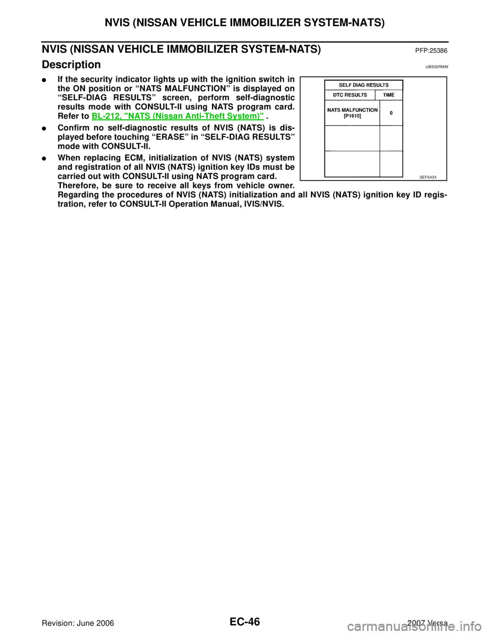
�If the security indicator lights up with the ignition switch in
the ON position or “NATS MALFUNCTION” is displayed on
“SELF-DIAG RESULTS” screen, perform self-diagnostic
results mode with CONSULT-II using NATS program card.
Refer to BL-212, "
NATS (Nissan Anti-Theft System)" .
�Confirm no self-diagnostic results of NVIS (NATS) is dis-
played before touching “ERASE” in “SELF-DIAG RESULTS”
mode with CONSULT-II.
�When replacing ECM, initialization of NVIS (NATS) system
and registration of all NVIS (NATS) ignition key IDs must be
carried out with CONSULT-II using NATS program card.
Therefore, be sure to receive all keys from vehicle owner.
Regarding the procedures of NVIS (NATS) initialization and all NVIS (NATS) ignition key ID regis-
tration, refer to CONSULT-II Operation Manual, IVIS/NVIS.
SEF 5 43 X