Page 2611 of 2896
SERVICE DATA AND SPECIFICATIONS (SDS)
PS-17
C
D
E
F
H
I
J
K
L
MA
B
PS
Revision: June 20062007 Versa
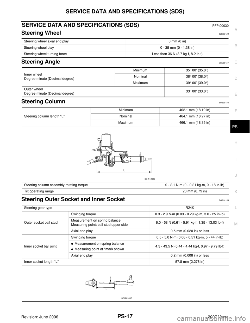
SERVICE DATA AND SPECIFICATIONS (SDS)PFP:00030
Steering WheelEGS00150
Steering AngleEGS00151
Steering ColumnEGS00152
Steering Outer Socket and Inner SocketEGS00153
Steering wheel axial end play 0 mm (0 in)
Steering wheel play 0 - 35 mm (0 - 1.38 in)
Steering wheel turning force Less than 36 N (3.7 kg-f, 8.2 lb-f)
Inner wheel
Degree minute (Decimal degree)Minimum 35° 00′ (35.0°)
Nominal 38° 00′ (38.0°)
Maximum 39° 00′ (39.0°)
Outer wheel
Degree minute (Decimal degree)33° 00′ (33.0°)
Steering column length “L”Minimum 462.1 mm (18.19 in)
Nominal 464.1 mm (18.27 in)
Maximum 466.1 mm (18.35 in)
Steering column assembly rotating torque 0 - 2.1 N·m (0 - 0.21 kg-m, 0 - 18 in-lb)
Tilt operating range20 mm (0.79 in)
SGIA1293E
Steering gear typeR24K
Outer socket ball studSwinging torque 0.3 - 2.9 N·m (0.03 - 0.29 kg-m, 3.0 - 25 in-lb)
Measurement on spring balance
Measuring point: ball stud upper side6.0 - 58 N (0.61 - 5.91 kg-f, 1.35 - 13.03 lb-f)
Axial end play 0.5 mm (0.020 in) or less
Inner socket ball jointSwinging torque 0.5 - 5.0 N·m (0.06 - 0.51 kg-m, 5 - 44 in-lb)
�Measurement on spring balance
�Measuring point at *mark shown4.3 - 43.5 N (0.44 - 4.44 kg-f, 0.97 - 9.79 lb-f)
Axial end play 0.2 mm (0.008 in) or less
Inner socket length “L”57.8 mm (2.276 in)
SGIA0950E
Page 2613 of 2896
RAX-1
REAR AXLE
D DRIVELINE/AXLE
CONTENTS
C
E
F
G
H
I
J
K
L
M
SECTION RAX
A
B
RAX
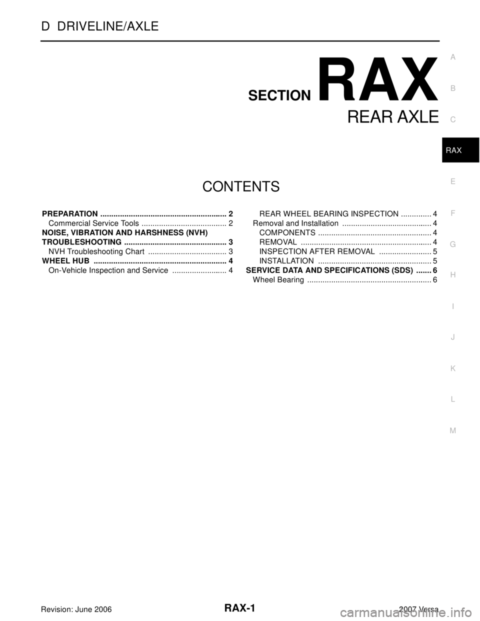
Revision: June 20062007 Versa PREPARATION ........................................................... 2
Commercial Service Tools ........................................ 2
NOISE, VIBRATION AND HARSHNESS (NVH)
TROUBLESHOOTING ................................................ 3
NVH Troubleshooting Chart ..................................... 3
WHEEL HUB .............................................................. 4
On-Vehicle Inspection and Service .......................... 4REAR WHEEL BEARING INSPECTION ............... 4
Removal and Installation .......................................... 4
COMPONENTS ..................................................... 4
REMOVAL ............................................................. 4
INSPECTION AFTER REMOVAL ......................... 5
INSTALLATION ..................................................... 5
SERVICE DATA AND SPECIFICATIONS (SDS) ........ 6
Wheel Bearing .......................................................... 6
Page 2614 of 2896
RAX-2
PREPARATION
Revision: June 20062007 Versa
PREPARATIONPFP:00002
Commercial Service ToolsEDS003QY
Tool name Description
Power tool Removing wheel nuts
PBIC0190E
Page 2615 of 2896
NOISE, VIBRATION AND HARSHNESS (NVH) TROUBLESHOOTING
RAX-3
C
E
F
G
H
I
J
K
L
MA
B
RAX
Revision: June 20062007 Versa
NOISE, VIBRATION AND HARSHNESS (NVH) TROUBLESHOOTINGPFP:00003
NVH Troubleshooting ChartEDS003QZ
Use chart below to help you find the cause of the symptom. If necessary, repair or replace these parts.
×: ApplicableReference page
RAX-4—
RAX-4
NVH in RAX and RSU sections.
NVH in WT section.
NVH in WT section.
NVH in BR section.
NVH in PS section.
Possible cause and SUSPECTED PARTS
Improper installation, looseness
Parts interference
Wheel bearing damage
REAR AXLE AND REAR SUSPENSION
TIRES
ROAD WHEEL
BRAKES
STEERING
Symptom REAR AXLENoise×× ×××××
Shake×× ×××××
Vibration×× ×× ×
Shimmy×× ×××××
Judder× ×××××
Poor quality ride or handling××××××
Page 2616 of 2896
RAX-4
WHEEL HUB
Revision: June 20062007 Versa
WHEEL HUBPFP:43202
On-Vehicle Inspection and ServiceEDS003R0
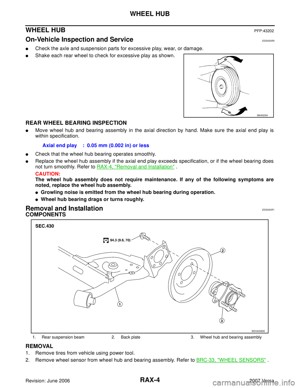
�Check the axle and suspension parts for excessive play, wear, or damage.
�Shake each rear wheel to check for excessive play as shown.
REAR WHEEL BEARING INSPECTION
�Move wheel hub and bearing assembly in the axial direction by hand. Make sure the axial end play is
within specification.
�Check that the wheel hub bearing operates smoothly.
�Replace the wheel hub assembly if the axial end play exceeds specification, or if the wheel bearing does
not turn smoothly. Refer to RAX-4, "
Removal and Installation" .
CAUTION:
The wheel hub assembly does not require maintenance. If any of the following symptoms are
noted, replace the wheel hub assembly.
�Growling noise is emitted from the wheel hub bearing during operation.
�Wheel hub bearing drags or turns roughly.
Removal and InstallationEDS003R1
COMPONENTS
REMOVAL
1. Remove tires from vehicle using power tool.
2. Remove wheel sensor from wheel hub and bearing assembly. Refer to BRC-33, "
WHEEL SENSORS" .
SM A52 5A
Axial end play : 0.05 mm (0.002 in) or less
1. Rear suspension beam 2. Back plate 3. Wheel hub and bearing assembly
WDIA0360E
Page 2617 of 2896
WHEEL HUB
RAX-5
C
E
F
G
H
I
J
K
L
MA
B
RAX
Revision: June 20062007 Versa
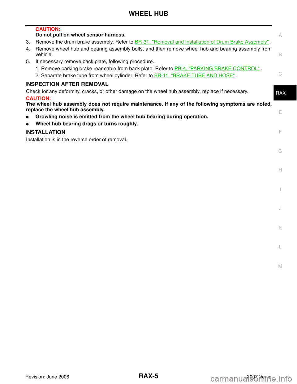
CAUTION:
Do not pull on wheel sensor harness.
3. Remove the drum brake assembly. Refer to BR-31, "
Removal and Installation of Drum Brake Assembly" .
4. Remove wheel hub and bearing assembly bolts, and then remove wheel hub and bearing assembly from
vehicle.
5. If necessary remove back plate, following procedure.
1. Remove parking brake rear cable from back plate. Refer to PB-4, "
PARKING BRAKE CONTROL" .
2. Separate brake tube from wheel cylinder. Refer to BR-11, "
BRAKE TUBE AND HOSE" .
INSPECTION AFTER REMOVAL
Check for any deformity, cracks, or other damage on the wheel hub assembly, replace if necessary.
CAUTION:
The wheel hub assembly does not require maintenance. If any of the following symptoms are noted,
replace the wheel hub assembly.
�Growling noise is emitted from the wheel hub bearing during operation.
�Wheel hub bearing drags or turns roughly.
INSTALLATION
Installation is in the reverse order of removal.
Page 2618 of 2896
RAX-6
SERVICE DATA AND SPECIFICATIONS (SDS)
Revision: June 20062007 Versa
SERVICE DATA AND SPECIFICATIONS (SDS)PFP:00030
Wheel BearingEDS003R2
Axial end play0.05 mm (0.002 in) or less
Page 2649 of 2896
RSU-1
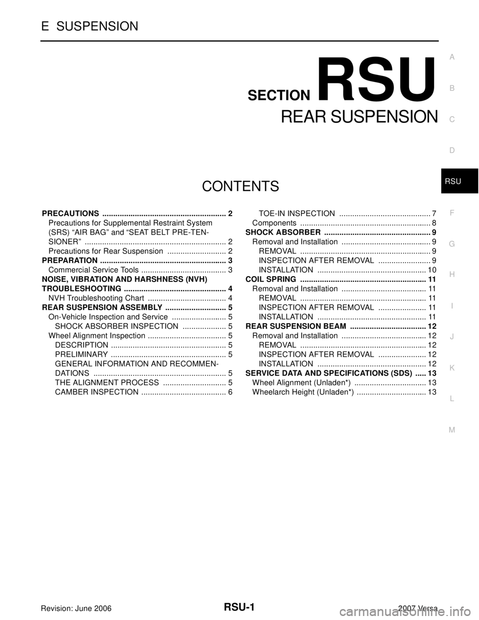
REAR SUSPENSION
E SUSPENSION
CONTENTS
C
D
F
G
H
I
J
K
L
M
SECTION RSU
A
B
RSU
Revision: June 20062007 Versa PRECAUTIONS .......................................................... 2
Precautions for Supplemental Restraint System
(SRS) “AIR BAG” and “SEAT BELT PRE-TEN-
SIONER” .................................................................. 2
Precautions for Rear Suspension ............................ 2
PREPARATION ........................................................... 3
Commercial Service Tools ........................................ 3
NOISE, VIBRATION AND HARSHNESS (NVH)
TROUBLESHOOTING ................................................ 4
NVH Troubleshooting Chart ..................................... 4
REAR SUSPENSION ASSEMBLY ............................. 5
On-Vehicle Inspection and Service .......................... 5
SHOCK ABSORBER INSPECTION ..................... 5
Wheel Alignment Inspection ..................................... 5
DESCRIPTION ...................................................... 5
PRELIMINARY ...................................................... 5
GENERAL INFORMATION AND RECOMMEN-
DATIONS .............................................................. 5
THE ALIGNMENT PROCESS .............................. 5
CAMBER INSPECTION ........................................ 6TOE-IN INSPECTION ........................................... 7
Components ............................................................. 8
SHOCK ABSORBER .................................................. 9
Removal and Installation .......................................... 9
REMOVAL ............................................................. 9
INSPECTION AFTER REMOVAL ......................... 9
INSTALLATION ................................................... 10
COIL SPRING ........................................................... 11
Removal and Installation ........................................ 11
REMOVAL ........................................................... 11
INSPECTION AFTER REMOVAL ....................... 11
INSTALLATION ................................................... 11
REAR SUSPENSION BEAM .................................... 12
Removal and Installation ........................................ 12
REMOVAL ........................................................... 12
INSPECTION AFTER REMOVAL ....................... 12
INSTALLATION ................................................... 12
SERVICE DATA AND SPECIFICATIONS (SDS) ...... 13
Wheel Alignment (Unladen*) .................................. 13
Wheelarch Height (Unladen*) ................................. 13