Page 2650 of 2896
 “AIR BAG” and “SEAT
BELT PRE-TENSIONER”
EES002FR
The Supplemental Rest")
RSU-2
PRECAUTIONS
Revision: June 20062007 Versa
PRECAUTIONSPFP:00001
Precautions for Supplemental Restraint System (SRS) “AIR BAG” and “SEAT
BELT PRE-TENSIONER”
EES002FR
The Supplemental Restraint System such as “AIR BAG” and “SEAT BELT PRE-TENSIONER”, used along
with a front seat belt, helps to reduce the risk or severity of injury to the driver and front passenger for certain
types of collision. This system includes seat belt switch inputs and dual stage front air bag modules. The SRS
system uses the seat belt switches to determine the front air bag deployment, and may only deploy one front
air bag, depending on the severity of a collision and whether the front occupants are belted or unbelted.
Information necessary to service the system safely is included in the SRS and SB section of this Service Man-
ual.
WAR NIN G:
�To avoid rendering the SRS inoperative, which could increase the risk of personal injury or death
in the event of a collision which would result in air bag inflation, all maintenance must be per-
formed by an authorized NISSAN/INFINITI dealer.
�Improper maintenance, including incorrect removal and installation of the SRS, can lead to per-
sonal injury caused by unintentional activation of the system. For removal of Spiral Cable and Air
Bag Module, see the SRS section.
�Do not use electrical test equipment on any circuit related to the SRS unless instructed to in this
Service Manual. SRS wiring harnesses can be identified by yellow and/or orange harnesses or
harness connectors.
Precautions for Rear SuspensionEES002FS
�When installing the rubber bushings, the final tightening must be done under unladen condition and with
the tires on level ground. Oil will shorten the life of the rubber bushings, so wipe off any spilled oil immedi-
ately.
�Unladen condition means the fuel tank, engine coolant and lubricants are at the full specification. The
spare tire, jack, hand tools, and mats are in their designated positions.
�After installing suspension components, check the wheel alignment.
�Caulking nuts are not reusable. Always use new caulking nuts for installation. New caulking nuts are pre-
oiled, do not apply any additional lubrication.
Page 2651 of 2896
PREPARATION
RSU-3
C
D
F
G
H
I
J
K
L
MA
B
RSU
Revision: June 20062007 Versa
PREPARATIONPFP:00002
Commercial Service ToolsEES002CV
To o l n a m eDescription
Power toolRemoving wheel nuts
PBIC0190E
Page 2652 of 2896
 TROUBLESHOOTING
Revision: June 20062007 Versa
NOISE, VIBRATION AND HARSHNESS (NVH) TROUBLESHOOTINGPFP:00003
NVH Troubleshooting ChartEES002CW
Use chart below")
RSU-4
NOISE, VIBRATION AND HARSHNESS (NVH) TROUBLESHOOTING
Revision: June 20062007 Versa
NOISE, VIBRATION AND HARSHNESS (NVH) TROUBLESHOOTINGPFP:00003
NVH Troubleshooting ChartEES002CW
Use chart below to help you find the cause of the symptom. If necessary, repair or replace these parts.
×: ApplicableReference page
RSU-8RSU-9RSU-9RSU-9RSU-11RSU-8RSU-5
RSU-4, "
NOISE, VIBRATION AND HARSHNESS (NVH) TROUBLESHOOTING
"
WT-4, "
NOISE, VIBRATION AND HARSHNESS (NVH) TROUBLESHOOTING
"
WT-4, "
NOISE, VIBRATION AND HARSHNESS (NVH) TROUBLESHOOTING
"
BR-5, "
NOISE, VIBRATION AND HARSHNESS (NVH) TROUBLESHOOTING
"
PS-5, "
NOISE, VIBRATION AND HARSHNESS (NVH) TROUBLESHOOTING
"
Possible cause and SUSPECTED PARTS
Improper installation, looseness
Shock absorber deformation, damage or deflection
Bushing or mounting deterioration
Parts interference
Spring fatigue
Suspension looseness
Incorrect wheel alignment
REAR AXLE
TIRES
ROAD WHEEL
BRAKES
STEERING
SymptomNoise×××××× ×××××
Shake×××× × ×××××
Vib ration××××× ×× ×
Shimmy×××× ××××××
Judder ××× ×××××
Poor quality ride or handling××××× ××××
Page 2653 of 2896

REAR SUSPENSION ASSEMBLY
RSU-5
C
D
F
G
H
I
J
K
L
MA
B
RSU
Revision: June 20062007 Versa
REAR SUSPENSION ASSEMBLYPFP:55020
On-Vehicle Inspection and ServiceEES002CX
Make sure the mounting conditions (looseness, backlash) of each component and component conditions
(wear, damage) are within specifications.
SHOCK ABSORBER INSPECTION
Check shock absorber for oil leakage, damage and replace it if necessary.
Wheel Alignment InspectionEES002CY
DESCRIPTION
Measure wheel alignment under unladen conditions.
NOTE:
“Unladen conditions” means that fuel, engine coolant, and lubricant are full. Spare tire, jack, hand tools and
mats are in designated positions.
PRELIMINARY
Check the following:
1. Tires for improper air pressure and wear.
2. Road wheels for runout. Refer to WT-5, "
ROAD WHEEL" .
3. Wheel bearing axial end play. Refer to RAX-4, "
REAR WHEEL BEARING INSPECTION" .
4. Shock absorber operation.
5. Each mounting part of suspension for looseness and deformation.
6. Rear suspension beam for cracks, deformation, and other damage.
7. Vehicle height (posture).
GENERAL INFORMATION AND RECOMMENDATIONS
1. A Four-Wheel Thrust Alignment should be performed.
�This type of alignment is recommended for any NISSAN vehicle.
�The four-wheel “thrust” process helps ensure that the vehicle is properly aligned and the steering wheel
is centered.
�The alignment machine itself should be capable of accepting any NISSAN vehicle.
�The alignment machine should be checked to ensure that it is level.
2. Make sure the alignment machine is properly calibrated.
�Your alignment machine should be regularly calibrated in order to give correct information.
�Check with the manufacturer of your specific alignment machine for their recommended Service/Cali-
bration Schedule.
THE ALIGNMENT PROCESS
IMPORTANT: Use only the alignment specifications listed in this Service Manual. Refer to RSU-13, "Wheel
Alignment (Unladen*)" .
1. When displaying the alignment settings, many alignment machines use “indicators”: (Green/red, plus or
minus, Go/No Go). Do NOT use these indicators.
�The alignment specifications programmed into your alignment machine that operate these indicators
may not be correct.
�This may result in an ERROR.
2. Some newer alignment machines are equipped with an optional “Rolling Compensation” method to “com-
pensate” the sensors (alignment targets or head units). Do NOT use this “Rolling Compensation”
method.
�Use the “Jacking Compensation” method. After installing the alignment targets or head units, raise the
vehicle and rotate the wheels 1/2 turn both ways.
�See Instructions in the alignment machine you are using for more information.
Page 2654 of 2896
RSU-6
REAR SUSPENSION ASSEMBLY
Revision: June 20062007 Versa
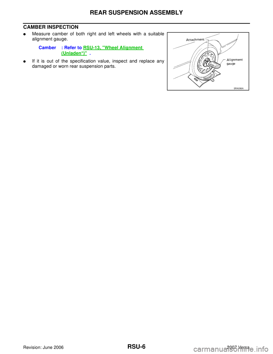
CAMBER INSPECTION
�Measure camber of both right and left wheels with a suitable
alignment gauge.
�If it is out of the specification value, inspect and replace any
damaged or worn rear suspension parts.Camber : Refer to RSU-13, "
Wheel Alignment
(Unladen*)" .
SRA0 96 A
Page 2655 of 2896

REAR SUSPENSION ASSEMBLY
RSU-7
C
D
F
G
H
I
J
K
L
MA
B
RSU
Revision: June 20062007 Versa
TOE-IN INSPECTION
Measure toe-in using following procedure. If it is out of the specification, inspect and replace any damaged or
worn rear suspension parts.
WA RN ING:
�Always perform the following procedure on a flat surface.
�Make sure that no person is in front of vehicle before pushing it.
1. Bounce the rear of vehicle up and down to stabilize the vehicle height (posture).
2. Push vehicle straight ahead about 5 m (16 ft).
3. Put a mark on base line of the tread (rear side) of both tires at
the same height of hub center. These are measuring points.
4. Measure distance “A” (rear side).
5. Push vehicle slowly ahead to rotate wheels 180 degrees (1/2
turn). If wheels have rotated more than 180 degrees (1/2 turn),
try the above procedure again from the beginning. Never push
vehicle backward.
6. Measure distance “B” (front side).
SEIA0362E
Total toe-in : Refer to RSU-13, "Wheel Alignment
(Unladen*)" .
SEIA0363E
Page 2657 of 2896

SHOCK ABSORBER
RSU-9
C
D
F
G
H
I
J
K
L
MA
B
RSU
Revision: June 20062007 Versa
SHOCK ABSORBERPFP:56210
Removal and InstallationEES002D0
REMOVAL
1. Remove rear tires from vehicle using power tool.
2. Remove wheel sensor from wheel hub and bearing assembly and rear suspension beam. Refer to BRC-
33, "WHEEL SENSORS" .
CAUTION:
Do not pull on wheel sensor harness.
3. Remove shock absorber mask from trunk side finisher using a flat-bladed screwdriver. Refer to EI-42,
"LUGGAGE FLOOR TRIM" .
CAUTION:
Wrap the tip of a screwdriver with cloth to avoid damaging components.
4. Set jack under rear suspension beam.
5. Remove upper nut of the shock absorber, and then remove
washer (upper), bushing (upper) from shock absorber.
6.
Remove shock absorber lower side bolt.
7. Gradually lower the jack, and remove the bushing (lower),
washer (lower), distance tube, bound bumper cover, bound
bumper and shock absorber from vehicle.
INSPECTION AFTER REMOVAL
Shock Absorber
Check the following:
�Shock absorber for deformation, cracks or damage, and replace if necessary.
�Piston rod for damage, uneven wear or distortion, and replace if necessary .
Bound Bumper and Bushing
Check bound bumper and bushing for cracks, deformation or other damage, and replace applicable parts if
necessary .
SEIA0147J
SEIA0146J
Page 2659 of 2896

COIL SPRING
RSU-11
C
D
F
G
H
I
J
K
L
MA
B
RSU
Revision: June 20062007 Versa
COIL SPRINGPFP:55020
Removal and InstallationEES002D1
REMOVAL
1. Remove rear tires from vehicle using power tool.
2. Remove wheel sensor from wheel hub and bearing assembly. Refer to BRC-33, "
WHEEL SENSORS" .
CAUTION:
Do not pull on wheel sensor harness.
3. Separate brake tube from wheel cylinder. Refer to BR-11, "
BRAKE TUBE AND HOSE" .
4. Set jack under rear suspension beam.
5. Remove shock absorber lower side bolt. Refer to RSU-9,
"SHOCK ABSORBER" .
6. Gradually lower the jack, and then remove coil spring and rear
spring rubber seat (upper and lower).
INSPECTION AFTER REMOVAL
Check coil spring and spring rubber seat for deformation, cracks, and damage, and replace it if a malfunction
is detected.
INSTALLATION
�Installation is in the reverse order of removal. For tightening torque, refer to RSU-8, "Components" .
�When installing spring, be sure to securely install the spring end
position aligned to flush of rear spring rubber seat (lower) as
shown.
SEIA0146J
SEIA0149J