Page 2152 of 2896
![NISSAN LATIO 2007 Service Repair Manual LAN-26
[CAN FUNDAMENTAL]
TROUBLE DIAGNOSES WORK FLOW
Revision: June 20062007 Versa
Present Error — Open Circuit —
Identify the error circuit using information from the “SELECT SYSTEM” and “C](/manual-img/5/57361/w960_57361-2151.png "NISSAN LATIO 2007 Service Repair Manual LAN-26
[CAN FUNDAMENTAL]
TROUBLE DIAGNOSES WORK FLOW
Revision: June 20062007 Versa
Present Error — Open Circuit —
Identify the error circuit using information from the “SELECT SYSTEM” and “C")
LAN-26
[CAN FUNDAMENTAL]
TROUBLE DIAGNOSES WORK FLOW
Revision: June 20062007 Versa
Present Error — Open Circuit —
Identify the error circuit using information from the “SELECT SYSTEM” and “CAN DIAG SUPPORT MNTR”
screens.
1. SELECT SYSTEM: Check the items indicated in “SELECT SYSTEM”. Draw a line on the diagnosis sheet
to indicate the error circuit.
NOTE:
CAN communication line has no error if units other than Diag on CAN units are indicated. An error may be
on the power supply of the control unit, DDL1 line or DDL2 line.
a. “TRANSMISSION” which is Diag on CAN unit, is not indicated on “SELECT SYSTEM” screen. This indi-
cates that DLC is not receiving a signal from TCM. Draw a line to indicate an error between DLC and TCM
(line 1-a in the figure).
NOTE:
�Diag on CAN units are not indicated on the “SELECT SYSTEM” screen when the CAN line between
Diag on CAN unit and the data link connector is open.
�For a description of Diag on CAN, refer to LAN-6, "Diag on CAN" .
SKIB8892E
Page 2158 of 2896
LAN-32
[CAN FUNDAMENTAL]
TROUBLE DIAGNOSES WORK FLOW
Revision: June 20062007 Versa
Present Error — Short Circuit —
When the symptoms listed below exist, a short circuit of the CAN communication line is a possible cause.
Received data
1.
Error symptom
�Most the units connected to the CAN communication system go into fail-safe mode or are deactivated.
Inspection procedure
�Refer to LAN-71, "Malfunction Area Chart" .
Item (CONSULT-II) Indication
SELECT SYSTEM All Diag on CAN units are not indicated.
CAN DIAG SUPPORT MNTR “UNKWN” is indicated under “TRANSMIT DIAG” and most reception items.
SKIB8894E
Page 2166 of 2896
![NISSAN LATIO 2007 Service Repair Manual LAN-40
[CAN]
INDEX FOR DTC
Revision: June 20062007 Versa
INDEX FOR DTCPFP:00004
DTC No. IndexUKS005YC
DTCSelf-diagnosis item
(CONSULT-II indication)DTC detection condition Inspection
U1000 CAN COMM C](/manual-img/5/57361/w960_57361-2165.png "NISSAN LATIO 2007 Service Repair Manual LAN-40
[CAN]
INDEX FOR DTC
Revision: June 20062007 Versa
INDEX FOR DTCPFP:00004
DTC No. IndexUKS005YC
DTCSelf-diagnosis item
(CONSULT-II indication)DTC detection condition Inspection
U1000 CAN COMM C")
LAN-40
[CAN]
INDEX FOR DTC
Revision: June 20062007 Versa
INDEX FOR DTCPFP:00004
DTC No. IndexUKS005YC
DTCSelf-diagnosis item
(CONSULT-II indication)DTC detection condition Inspection
U1000 CAN COMM CIRCUITWhen ECM is not transmitting or receiving CAN
communication signal of OBD (emission-related
diagnosis) for 2 seconds or more.
Refer to LAN-41, "
HOW
TO USE THIS SEC-
TION" . When a control unit (except for ECM) is not
transmitting or receiving CAN communication
signal for 2 seconds or more.
U1001 CAN COMM CIRCUITWhen ECM is not transmitting or receiving CAN
communication signal other than OBD (emis-
sion-related diagnosis) for 2 seconds or more.
U1002 SYSTEM COMMWhen a control unit is not transmitting or receiv-
ing CAN communication signal for 2 seconds or
less.Start the inspection.
Refer to the applicable
section of the indicated
control unit.
U1010 CONTROL UNIT [CAN]When an error is detected during the initial diag-
nosis for CAN controller of each control unit.Replace the control unit
indicating “U1010”.
Page 2167 of 2896
HOW TO USE THIS SECTION
LAN-41
[CAN]
C
D
E
F
G
H
I
J
L
MA
B
LAN
Revision: June 20062007 Versa
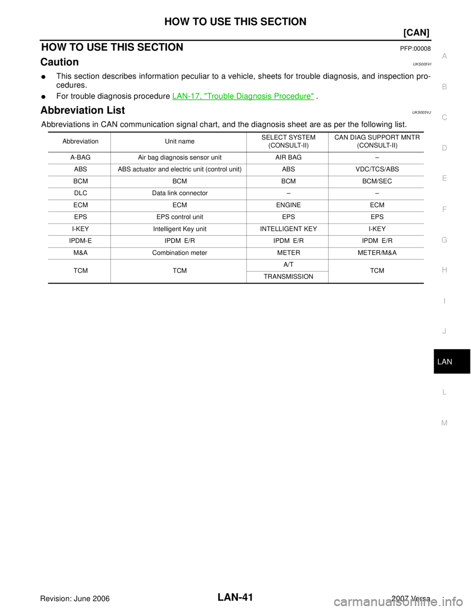
HOW TO USE THIS SECTIONPFP:00008
CautionUKS005VI
�This section describes information peculiar to a vehicle, sheets for trouble diagnosis, and inspection pro-
cedures.
�For trouble diagnosis procedure LAN-17, "Trouble Diagnosis Procedure" .
Abbreviation ListUKS005VJ
Abbreviations in CAN communication signal chart, and the diagnosis sheet are as per the following list.
Abbreviation Unit nameSELECT SYSTEM
(CONSULT-II)CAN DIAG SUPPORT MNTR
(CONSULT-II)
A-BAG Air bag diagnosis sensor unit AIR BAG –
ABS ABS actuator and electric unit (control unit) ABS VDC/TCS/ABS
BCM BCM BCM BCM/SEC
DLC Data link connector – –
ECM ECM ENGINE ECM
EPS EPS control unit EPS EPS
I-KEY Intelligent Key unit INTELLIGENT KEY I-KEY
IPDM-E IPDM E/R IPDM E/R IPDM E/R
M&A Combination meter METER METER/M&A
TCM TCMA/T
TCM
TRANSMISSION
Page 2168 of 2896
![NISSAN LATIO 2007 Service Repair Manual LAN-42
[CAN]
PRECAUTIONS
Revision: June 20062007 Versa
PRECAUTIONSPFP:00001
Precautions for Supplemental Restraint System (SRS) “AIR BAG” and “SEAT
BELT PRE-TENSIONER”
UKS005VK
The Supplement](/manual-img/5/57361/w960_57361-2167.png "NISSAN LATIO 2007 Service Repair Manual LAN-42
[CAN]
PRECAUTIONS
Revision: June 20062007 Versa
PRECAUTIONSPFP:00001
Precautions for Supplemental Restraint System (SRS) “AIR BAG” and “SEAT
BELT PRE-TENSIONER”
UKS005VK
The Supplement")
LAN-42
[CAN]
PRECAUTIONS
Revision: June 20062007 Versa
PRECAUTIONSPFP:00001
Precautions for Supplemental Restraint System (SRS) “AIR BAG” and “SEAT
BELT PRE-TENSIONER”
UKS005VK
The Supplemental Restraint System such as “AIR BAG” and “SEAT BELT PRE-TENSIONER”, used along
with a front seat belt, helps to reduce the risk or severity of injury to the driver and front passenger for certain
types of collision. This system includes seat belt switch inputs and dual stage front air bag modules. The SRS
system uses the seat belt switches to determine the front air bag deployment, and may only deploy one front
air bag, depending on the severity of a collision and whether the front occupants are belted or unbelted.
Information necessary to service the system safely is included in the SRS and SB section of this Service Man-
ual.
WAR NIN G:
�To avoid rendering the SRS inoperative, which could increase the risk of personal injury or death
in the event of a collision which would result in air bag inflation, all maintenance must be per-
formed by an authorized NISSAN/INFINITI dealer.
�Improper maintenance, including incorrect removal and installation of the SRS, can lead to per-
sonal injury caused by unintentional activation of the system. For removal of Spiral Cable and Air
Bag Module, see the SRS section.
�Do not use electrical test equipment on any circuit related to the SRS unless instructed to in this
Service Manual. SRS wiring harnesses can be identified by yellow and/or orange harnesses or
harness connectors.
Precautions When Using CONSULT-IIUKS005YD
Use CONSULT-II CONVERTER when connecting CONSULT-II to data link connector.
CAUTION:
CAN communication does not function properly if CONSULT-II is used without connecting CONSULT-II
CONVERTER.
Precautions for Trouble DiagnosisUKS005YE
CAUTION:
�Never apply 7.0 V or more to the measurement terminal.
�Use a tester with open terminal voltage of 7.0 V or less.
�Turn the ignition switch OFF and disconnect the battery cable from the negative terminal when
checking the harness.
Precautions for Harness RepairUKS005YF
�Solder the repaired area and wrap tape around the soldered
area.
NOTE:
A fray of twisted lines must be within 110 mm (4.33 in).
SKIB8766E
Page 2173 of 2896
TROUBLE DIAGNOSIS
LAN-47
[CAN]
C
D
E
F
G
H
I
J
L
MA
B
LAN
Revision: June 20062007 Versa
CAN System Specification ChartUKS005VP
Check CAN system type from the following specification chart. Then choose the correct diagnosis sheet.
NOTE:
Refer to LAN-19, "
CHECK OF CAN SYSTEM TYPE (HOW TO USE CAN SYSTEM TYPE SPECIFICATION
CHART)" for how to use CAN system specification chart.
X: Applicable
VEHICLE EQUIPMENT IDENTIFICATION INFORMATION
NOTE:
Check CAN system type from the vehicle shape and equipment.
Body type Hatchback
Axle2WD
EngineMR18DE
Transmission M/T A/T CVT
Brake control — ABS — ABS — ABS
Intelligent Key system×× ××
CAN system type 12345678910
Diagnosis sheetLAN-
60
LAN-
61
LAN-
62
LAN-
63
LAN-
64
LAN-
65
LAN-
66
LAN-
67
LAN-
68
LAN-
69
CAN communication signal chartLAN-48, "TYPE 1/TYPE 2/TYPE 3/
TYPE 4"
LAN-49, "TYPE
5/TYPE 6"
LAN-50, "TYPE 7/TYPE 8/TYPE 9/
TYPE 10"
BKIA0210E
Page 2175 of 2896
![NISSAN LATIO 2007 Service Repair Manual TROUBLE DIAGNOSIS
LAN-49
[CAN]
C
D
E
F
G
H
I
J
L
MA
B
LAN
Revision: June 20062007 Versa
*1: Models with Intelligent Key system
*2: Models with ABS
*3: Models with air conditioner
*4: Models for Canada](/manual-img/5/57361/w960_57361-2174.png "NISSAN LATIO 2007 Service Repair Manual TROUBLE DIAGNOSIS
LAN-49
[CAN]
C
D
E
F
G
H
I
J
L
MA
B
LAN
Revision: June 20062007 Versa
*1: Models with Intelligent Key system
*2: Models with ABS
*3: Models with air conditioner
*4: Models for Canada")
TROUBLE DIAGNOSIS
LAN-49
[CAN]
C
D
E
F
G
H
I
J
L
MA
B
LAN
Revision: June 20062007 Versa
*1: Models with Intelligent Key system
*2: Models with ABS
*3: Models with air conditioner
*4: Models for Canada
*5: Models for USA
NOTE:
CAN data of the air bag diagnosis sensor unit is not used by usual service work, thus it is omitted.
TYPE 5/TYPE 6
NOTE:
Refer to LAN-41, "
Abbreviation List" for the abbreviations of the connecting units.
T: Transmit R: Receive Sleep/wake up signalRT
TRRR
Vehicle speed signalRRR T
RRRT
ABS warning lamp signalRT
Brake warning lamp signalRT
Front wiper stop position signal R T
High beam status signal RT
Low beam status signal RT
Oil pressure switch signalRT
Rear window defogger control signal RT Signals ECM BCM EPS
I-KEY
*1M&A
ABS*2IPDM-E
Signals ECM BCM EPS M&A
ABS*1TCM IPDM-E
A/C compressor request signal
*2TR
Accelerator pedal position signal T R
ASCD CRUISE lamp signal T R
ASCD SET lamp signal T R
Closed throttle position signal T R
Cooling fan motor operation signal TR
Engine coolant temperature signal T R
Engine speed signal T R
Engine status signal T R
Fuel consumption monitor signal T R
Malfunction indicator lamp signal T R
Wide open throttle position signal T R
A/C switch signal
*2RT
Blower fan motor switch signal R T
Buzzer output signalTR
R
Day time running light request signal
*3TR
Door switch signal T R R
Front wiper request signal T R
High beam request signal T R R
Horn chirp signal T R
Ignition switch signal T R
Page 2178 of 2896
LAN-52
[CAN]
TROUBLE DIAGNOSIS
Revision: June 20062007 Versa
*1: Models with Intelligent Key system
*2: Models with ABS
*3: Models for Canada
*4: Models for USA
*5: Models without ABS
NOTE:
CAN data of the air bag diagnosis sensor unit is not used by usual service work, thus it is omitted.
Input shaft revolution signal R T
Output shaft revolution signal R T
Shift position indicator signal R T
OD OFF indicator signal R T
Front wiper stop position signal R T
High beam status signal RT
Low beam status signal RT
Oil pressure switch signal R T
Rear window defogger control signal RT Signals ECM BCM EPS
I-KEY
*1M&A
ABS*2TCM IPDM-E
![NISSAN LATIO 2007 Service Repair Manual LAN-32
[CAN FUNDAMENTAL]
TROUBLE DIAGNOSES WORK FLOW
Revision: June 20062007 Versa
Present Error — Short Circuit —
When the symptoms listed below exist, a short circuit of the CAN communication li](/manual-img/5/57361/w960_57361-2157.png "NISSAN LATIO 2007 Service Repair Manual LAN-32
[CAN FUNDAMENTAL]
TROUBLE DIAGNOSES WORK FLOW
Revision: June 20062007 Versa
Present Error — Short Circuit —
When the symptoms listed below exist, a short circuit of the CAN communication li")
![NISSAN LATIO 2007 Service Repair Manual TROUBLE DIAGNOSIS
LAN-47
[CAN]
C
D
E
F
G
H
I
J
L
MA
B
LAN
Revision: June 20062007 Versa
CAN System Specification ChartUKS005VP
Check CAN system type from the following specification chart. Then choose](/manual-img/5/57361/w960_57361-2172.png "NISSAN LATIO 2007 Service Repair Manual TROUBLE DIAGNOSIS
LAN-47
[CAN]
C
D
E
F
G
H
I
J
L
MA
B
LAN
Revision: June 20062007 Versa
CAN System Specification ChartUKS005VP
Check CAN system type from the following specification chart. Then choose")
![NISSAN LATIO 2007 Service Repair Manual LAN-52
[CAN]
TROUBLE DIAGNOSIS
Revision: June 20062007 Versa
*1: Models with Intelligent Key system
*2: Models with ABS
*3: Models for Canada
*4: Models for USA
*5: Models without ABS
NOTE:
CAN data o](/manual-img/5/57361/w960_57361-2177.png "NISSAN LATIO 2007 Service Repair Manual LAN-52
[CAN]
TROUBLE DIAGNOSIS
Revision: June 20062007 Versa
*1: Models with Intelligent Key system
*2: Models with ABS
*3: Models for Canada
*4: Models for USA
*5: Models without ABS
NOTE:
CAN data o")