Page 2174 of 2896
![NISSAN LATIO 2007 Service Repair Manual LAN-48
[CAN]
TROUBLE DIAGNOSIS
Revision: June 20062007 Versa
CAN Communication Signal ChartUKS005VQ
Refer to LAN-15, "How to Use CAN Communication Signal Chart" for how to use CAN communication signa NISSAN LATIO 2007 Service Repair Manual LAN-48
[CAN]
TROUBLE DIAGNOSIS
Revision: June 20062007 Versa
CAN Communication Signal ChartUKS005VQ
Refer to LAN-15, "How to Use CAN Communication Signal Chart" for how to use CAN communication signa](/manual-img/5/57361/w960_57361-2173.png)
LAN-48
[CAN]
TROUBLE DIAGNOSIS
Revision: June 20062007 Versa
CAN Communication Signal ChartUKS005VQ
Refer to LAN-15, "How to Use CAN Communication Signal Chart" for how to use CAN communication signal
chart.
TYPE 1/TYPE 2/TYPE 3/TYPE 4
NOTE:
Refer to LAN-41, "
Abbreviation List" for the abbreviations of the connecting units.
T: Transmit R: Receive
Signals ECM BCM EPS
I-KEY
*1M&A
ABS*2IPDM-E
A/C compressor request signal
*3TR
ASCD CRUISE lamp signal T R
ASCD SET lamp signal T R
Cooling fan motor operation signal TR
Engine coolant temperature signal T R
Engine speed signal T R
Engine status signal T R
Fuel consumption monitor signal T R
Malfunction indicator lamp signal T R
A/C switch signal
*3RT
Blower fan motor switch signal R T
Buzzer output signalTR
TR
Day time running light request signal
*4TR
Door lock/unlock status signal T R
Door switch signal T R R R
Front wiper request signal T R
High beam request signal T R R
Horn chirp signal T R
Ignition switch signal T R
Low beam request signal T R
Position lights request signal T R R
Rear window defogger switch signal T R
Theft warning horn request signal T R
Tire pressure signal
*5TR
Trunk open/close status signal T R
Turn indicator signal T R
EPS operation signal R T
EPS warning lamp signal T R
Door lock/unlock/trunk open request signal R T
Hazard request signal R T
Ignition knob switch signal R T
KEY warning lamp signal T R
LOCK warning lamp signal T R
Panic alarm request signal R T
Fuel level sensor signal R T
Page 2175 of 2896
![NISSAN LATIO 2007 Service Repair Manual TROUBLE DIAGNOSIS
LAN-49
[CAN]
C
D
E
F
G
H
I
J
L
MA
B
LAN
Revision: June 20062007 Versa
*1: Models with Intelligent Key system
*2: Models with ABS
*3: Models with air conditioner
*4: Models for Canada NISSAN LATIO 2007 Service Repair Manual TROUBLE DIAGNOSIS
LAN-49
[CAN]
C
D
E
F
G
H
I
J
L
MA
B
LAN
Revision: June 20062007 Versa
*1: Models with Intelligent Key system
*2: Models with ABS
*3: Models with air conditioner
*4: Models for Canada](/manual-img/5/57361/w960_57361-2174.png)
TROUBLE DIAGNOSIS
LAN-49
[CAN]
C
D
E
F
G
H
I
J
L
MA
B
LAN
Revision: June 20062007 Versa
*1: Models with Intelligent Key system
*2: Models with ABS
*3: Models with air conditioner
*4: Models for Canada
*5: Models for USA
NOTE:
CAN data of the air bag diagnosis sensor unit is not used by usual service work, thus it is omitted.
TYPE 5/TYPE 6
NOTE:
Refer to LAN-41, "
Abbreviation List" for the abbreviations of the connecting units.
T: Transmit R: Receive Sleep/wake up signalRT
TRRR
Vehicle speed signalRRR T
RRRT
ABS warning lamp signalRT
Brake warning lamp signalRT
Front wiper stop position signal R T
High beam status signal RT
Low beam status signal RT
Oil pressure switch signalRT
Rear window defogger control signal RT Signals ECM BCM EPS
I-KEY
*1M&A
ABS*2IPDM-E
Signals ECM BCM EPS M&A
ABS*1TCM IPDM-E
A/C compressor request signal
*2TR
Accelerator pedal position signal T R
ASCD CRUISE lamp signal T R
ASCD SET lamp signal T R
Closed throttle position signal T R
Cooling fan motor operation signal TR
Engine coolant temperature signal T R
Engine speed signal T R
Engine status signal T R
Fuel consumption monitor signal T R
Malfunction indicator lamp signal T R
Wide open throttle position signal T R
A/C switch signal
*2RT
Blower fan motor switch signal R T
Buzzer output signalTR
R
Day time running light request signal
*3TR
Door switch signal T R R
Front wiper request signal T R
High beam request signal T R R
Horn chirp signal T R
Ignition switch signal T R
Page 2177 of 2896
![NISSAN LATIO 2007 Service Repair Manual TROUBLE DIAGNOSIS
LAN-51
[CAN]
C
D
E
F
G
H
I
J
L
MA
B
LAN
Revision: June 20062007 Versa
Cooling fan motor operation signal TR
Engine coolant temperature signal T R
Engine speed signal T R R
Engine sta NISSAN LATIO 2007 Service Repair Manual TROUBLE DIAGNOSIS
LAN-51
[CAN]
C
D
E
F
G
H
I
J
L
MA
B
LAN
Revision: June 20062007 Versa
Cooling fan motor operation signal TR
Engine coolant temperature signal T R
Engine speed signal T R R
Engine sta](/manual-img/5/57361/w960_57361-2176.png)
TROUBLE DIAGNOSIS
LAN-51
[CAN]
C
D
E
F
G
H
I
J
L
MA
B
LAN
Revision: June 20062007 Versa
Cooling fan motor operation signal TR
Engine coolant temperature signal T R
Engine speed signal T R R
Engine status signal T R
Fuel consumption monitor signal T R
Malfunction indicator lamp signal T R
Wide open throttle position signal T R
A/C switch signal R T
Blower fan motor switch signal R T
Buzzer output signalTR
TR
Day time running light request signal
*3TRR
Door lock/unlock status signal T R
Door switch signal T R R R
Front wiper request signal T R
High beam request signal T R R
Horn chirp signal T R
Ignition switch signal T R
Low beam request signal T R
Position lights request signal T R R
Rear window defogger switch signal T R
Theft warning horn request signal T R
Tire pressure signal
*4
Trunk open/close status signal T R
Turn indicator signal T R
EPS operation signal R T
EPS warning lamp signal T R
Door lock/unlock/trunk open request signal R T
Hazard request signal R T
Ignition knob switch signal R T
KEY warning lamp signal T R
LOCK warning lamp signal T R
Panic alarm request signal R T
Fuel level sensor signal R T
Sleep/wake up signalRT
TRR R
Overdrive control switch signal T R
Stop lamp switch signal T R
Vehicle speed signalRRR T
RRRTR
R
*5R*5T*5
ABS warning lamp signal R T
Brake warning lamp signal R T
CVT self-diagnosis signal R TSignals ECM BCM EPS
I-KEY
*1M&A
ABS*2TCM IPDM-E
Page 2231 of 2896
HEADLAMP (FOR USA)
LT-23
C
D
E
F
G
H
I
J
L
MA
B
LT
Revision: June 20062007 Versa
3. CHECKING CAN COMMUNICATIONS BETWEEN BCM AND IPDM E/R
Select “BCM” on CONSULT-II, and perform self-diagnosis for
“BCM”.
Display of self
-diagnosis results
NO DTC>> Replace IPDM E/R. Refer to PG-29, "Removal and
Installation of IPDM E/R" .
CAN COMM CIRCUIT>> Refer to LAN-44, "
TROUBLE DIAGNO-
SIS" .
Aiming AdjustmentEKS00IMG
PREPARATION BEFORE ADJUSTING
Before performing aiming adjustment, check the following.
1. Keep all tires inflated to correct pressures.
2. Place vehicle on level surface.
3. Set that there is no-load in vehicle other than the driver (or equivalent weight placed in driver's position).
Coolant, engine oil filled up to correct level and full fuel tank.
LOW BEAM AND HIGH BEAM
1. Turn headlamp low beam ON.
2. Use adjusting screw to perform aiming adjustment.
PKIA7627E
1. Headlamp A. Inner and outer adjustment B. Adjusting screw
WKIA5417E
Page 2245 of 2896

HEADLAMP (FOR CANADA) - DAYTIME LIGHT SYSTEM -
LT-37
C
D
E
F
G
H
I
J
L
MA
B
LT
Revision: June 20062007 Versa
6. CHECK DAYTIME LIGHT RELAY 1 CONTROL CIRCUIT
1. Turn ignition switch OFF.
2. Disconnect daytime light relay 1 connector E37.
3. Disconnect IPDM E/R connector E43.
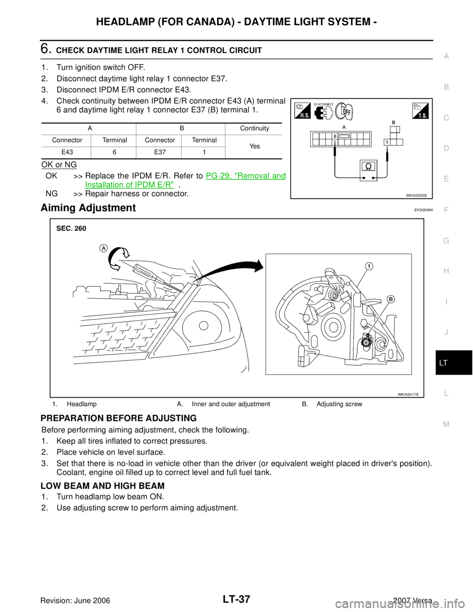
4. Check continuity between IPDM E/R connector E43 (A) terminal
6 and daytime light relay 1 connector E37 (B) terminal 1.
OK or NG
OK >> Replace the IPDM E/R. Refer to PG-29, "Removal and
Installation of IPDM E/R" .
NG >> Repair harness or connector.
Aiming AdjustmentEKS00IM4
PREPARATION BEFORE ADJUSTING
Before performing aiming adjustment, check the following.
1. Keep all tires inflated to correct pressures.
2. Place vehicle on level surface.
3. Set that there is no-load in vehicle other than the driver (or equivalent weight placed in driver's position).
Coolant, engine oil filled up to correct level and full fuel tank.
LOW BEAM AND HIGH BEAM
1. Turn headlamp low beam ON.
2. Use adjusting screw to perform aiming adjustment.
A B Continuity
Connector Terminal Connector Terminal
Ye s
E43 6 E37 1
WKIA5553E
1. Headlamp A. Inner and outer adjustment B. Adjusting screw
WKIA5417E
Page 2257 of 2896

FRONT FOG LAMP
LT-49
C
D
E
F
G
H
I
J
L
MA
B
LT
Revision: June 20062007 Versa
Aiming AdjustmentEKS00HXJ
The front fog lamp is a semi-sealed beam type which uses a replaceable halogen bulb. Before performing
aiming adjustment, make sure of the following.
�Keep all tires inflated to correct pressure.
�Place vehicle on level surface.
�Set that there is no-load in vehicle other than the driver (or equivalent weight placed in driver’s position).
Coolant, engine oil filled up to correct level and full fuel tank.
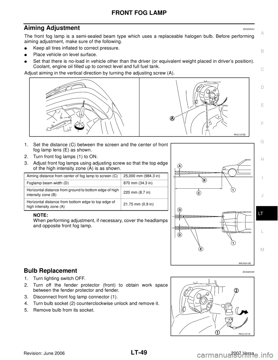
Adjust aiming in the vertical direction by turning the adjusting screw (A).
1. Set the distance (C) between the screen and the center of front
fog lamp lens (E) as shown.
2. Turn front fog lamps (1) to ON.
3. Adjust front fog lamps using adjusting screw so that the top edge
of the high intensity zone (A) is as shown.
NOTE:
When performing adjustment, if necessary, cover the headlamps
and opposite front fog lamp.
Bulb ReplacementEKS00HXK
1. Turn lighting switch OFF.
2. Turn off the fender protector (front) to obtain work space
between the fender protector and fender.
3. Disconnect front fog lamp connector (1).
4. Turn bulb socket (2) counterclockwise unlock and remove it.
5. Remove bulb from its socket.
PKIC1070E
Aiming distance from center of fog lamp to screen (C) 25,000 mm (984.3 in)
Foglamp beam width (D) 870 mm (34.3 in)
Horizontal distance from ground to bottom edge of high
intensity zone (B)220 mm (8.7 in)
Horizontal distance from bottom edge to top edge of
high intensity zone (A)21.75 mm (0.9 in)
WKIA5419E
PKIC1071E
Page 2326 of 2896

LU-2Revision: June 2006
PRECAUTIONS
2007 Versa
PRECAUTIONSPFP:00001
Precautions for Liquid GasketEBS00T6X
LIQUID GASKET APPLICATION PROCEDURE
1. Remove old liquid gasket adhering to the liquid gasket application surface and the mating surface.
�Remove liquid gasket completely from the liquid gasket application surface, bolts, and bolt holes.
2. Wipe the liquid gasket application surface and the mating surface with white gasoline (lighting and heating
use) to remove adhering moisture, grease and foreign materials.
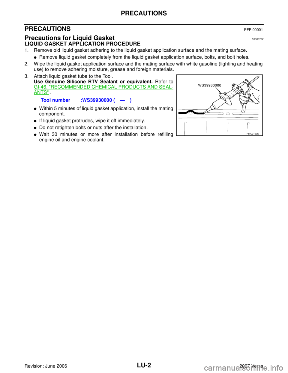
3. Attach liquid gasket tube to the Tool.
Use Genuine Silicone RTV Sealant or equivalent. Refer to
GI-46, "
RECOMMENDED CHEMICAL PRODUCTS AND SEAL-
ANTS" .
�Within 5 minutes of liquid gasket application, install the mating
component.
�If liquid gasket protrudes, wipe it off immediately.
�Do not retighten bolts or nuts after the installation.
�Wait 30 minutes or more after installation before refilling
engine oil and engine coolant.Tool number :WS39930000 ( — )PBIC2160E
Page 2329 of 2896

ENGINE OIL
LU-5
C
D
E
F
G
H
I
J
K
L
MA
LU
Revision: June 20062007 Versa
ENGINE OILPFP:KLA92
InspectionEBS00T71
ENGINE OIL LEVEL
NOTE:
Before starting engine, park vehicle on a level surface and check the engine oil level. If engine is already
started, stop it and allow 10 minutes before checking.
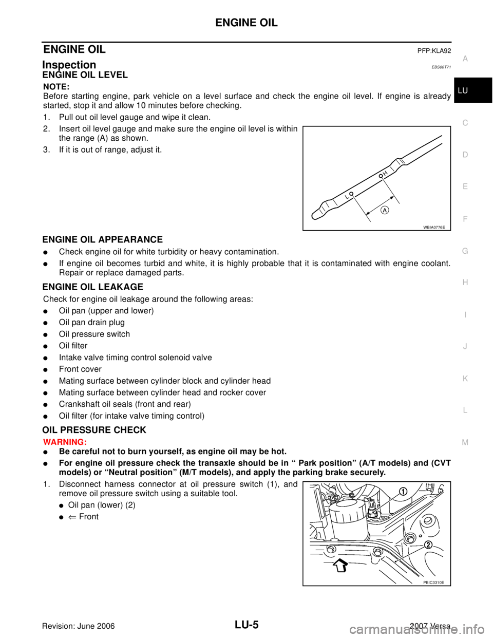
1. Pull out oil level gauge and wipe it clean.
2. Insert oil level gauge and make sure the engine oil level is within
the range (A) as shown.
3. If it is out of range, adjust it.
ENGINE OIL APPEARANCE
�Check engine oil for white turbidity or heavy contamination.
�If engine oil becomes turbid and white, it is highly probable that it is contaminated with engine coolant.
Repair or replace damaged parts.
ENGINE OIL LEAKAGE
Check for engine oil leakage around the following areas:
�Oil pan (upper and lower)
�Oil pan drain plug
�Oil pressure switch
�Oil filter
�Intake valve timing control solenoid valve
�Front cover
�Mating surface between cylinder block and cylinder head
�Mating surface between cylinder head and rocker cover
�Crankshaft oil seals (front and rear)
�Oil filter (for intake valve timing control)
OIL PRESSURE CHECK
WA RN ING:
�Be careful not to burn yourself, as engine oil may be hot.
�For engine oil pressure check the transaxle should be in “ Park position” (A/T models) and (CVT
models) or “Neutral position” (M/T models), and apply the parking brake securely.
1. Disconnect harness connector at oil pressure switch (1), and
remove oil pressure switch using a suitable tool.
�Oil pan (lower) (2)
�⇐ Front
WBIA0776E
PBIC3310E