FRONT WIPER AND WASHER SYSTEM
WW-9
C
D
E
F
G
H
I
J
L
MA
B
WW
Revision: 2006 November2007 350Z
NOTE:
Each OUTPUT terminal transistor is activated at 10 ms intervals. Therefore after switch is turned ON, electri-
cal loads are activated with time delay. But this time delay is so short that it cannot be detected by human
senses.
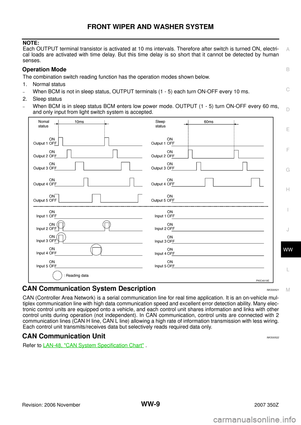
Operation Mode
The combination switch reading function has the operation modes shown below.
1. Normal status
–When BCM is not in sleep status, OUTPUT terminals (1 - 5) each turn ON-OFF every 10 ms.
2. Sleep status
–When BCM is in sleep status BCM enters low power mode. OUTPUT (1 - 5) turn ON-OFF every 60 ms,
and only input from light switch system is accepted.
CAN Communication System DescriptionNKS00521
CAN (Controller Area Network) is a serial communication line for real time application. It is an on-vehicle mul-
tiplex communication line with high data communication speed and excellent error detection ability. Many elec-
tronic control units are equipped onto a vehicle, and each control unit shares information and links with other
control units during operation (not independent). In CAN communication, control units are connected with 2
communication lines (CAN H line, CAN L line) allowing a high rate of information transmission with less wiring.
Each control unit transmits/receives data but selectively reads required data only.
CAN Communication UnitNKS00522
Refer to LAN-48, "CAN System Specification Chart" .
PKIC4919E