Page 4 of 54

WW-4
FRONT WIPER AND WASHER SYSTEM
Revision: 2006 November2007 350Z
FRONT WIPER AND WASHER SYSTEMPFP:28810
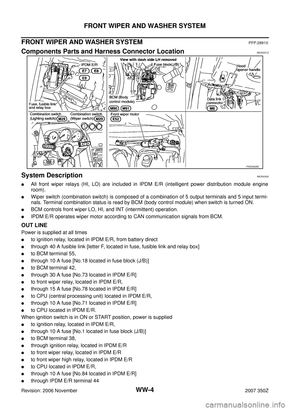
Components Parts and Harness Connector LocationNKS0051Z
System DescriptionNKS00520
�All front wiper relays (HI, LO) are included in IPDM E/R (intelligent power distribution module engine
room).
�Wiper switch (combination switch) is composed of a combination of 5 output terminals and 5 input termi-
nals. Terminal combination status is read by BCM (body control module) when switch is turned ON.
�BCM controls front wiper LO, HI, and INT (intermittent) operation.
�IPDM E/R operates wiper motor according to CAN communication signals from BCM.
OUT LINE
Power is supplied at all times
�to ignition relay, located in IPDM E/R, from battery direct
�through 40 A fusible link [letter F, located in fuse, fusible link and relay box]
�to BCM terminal 55,
�through 10 A fuse [No.18 located in fuse block (J/B)]
�to BCM terminal 42,
�through 30 A fuse [No.73 located in IPDM E/R]
�to front wiper relay, located in IPDM E/R,
�through 15 A fuse [No.78 located in IPDM E/R]
�to CPU (central processing unit) located in IPDM E/R,
�through 10 A fuse [No.71 located in IPDM E/R]
�to CPU located in IPDM E/R.
When ignition switch is in ON or START position, power is supplied
�to ignition relay, located in IPDM E/R,
�through 10 A fuse [No.1 located in fuse block (J/B)]
�to BCM terminal 38,
�through ignition relay, located in IPDM E/R
�to front wiper relay, located in IPDM E/R
�to front wiper high relay, located in IPDM E/R
�to CPU located in IPDM E/R,
�through 10 A fuse [No.84 located in IPDM E/R]
�through IPDM E/R terminal 44
PKID0828E
Page 20 of 54

WW-20
FRONT WIPER AND WASHER SYSTEM
Revision: 2006 November2007 350Z
NOTE:
Coupe models
CONSULT-III Function (IPDM E/R)NKS0052A
CONSULT-III can display each diagnostic item using the diagnostic test mode shown following.
DATA MONITOR
All Signals, Main Signals, Selection From Menu
NOTE:
Perform monitoring of IPDM E/R data with ignition switch ON. When ignition switch is at ACC, the display may
not be correct.
ACTIVE TEST
Display Item List
Diagnosis Mode Description
SELF−DIAG RESULTS Refer to PG-18, "
SELF-DIAG RESULTS" .
DATA MONITOR The input/output data of IPDM E/R is displayed in real time.
CAN DIAG SUPPORT MNTR The result of transmit/receive diagnosis of CAN communication can be read.
ACTIVE TEST IPDM E/R sends a drive signal to electronic components to check their operation.
Item nameCONSULT-III
screen displayDisplay or unitMonitor item selection
Description
ALL
SIGNALSMAIN
SIGNALSSELECTION
FROM MENU
FR wiper request FR WIP REQ STOP/LOW/HI×× ×Signal status input from BCM
Wiper auto stop WIP AUTO STOP ACT P/STOP P×× ×Output status of IPDM E/R
Wiper protection WIP PROT OFF/Block×× ×Control status of IPDM E/R
Test item CONSULT-III screen display Description
Front wiper (HI, LO) output FR WIPERWith a certain operation (OFF, HI ON, LO ON), front wiper relay (and/or
front wiper high relay) can be operated.
Page 28 of 54

WW-28
FRONT WIPER AND WASHER SYSTEM
Revision: 2006 November2007 350Z
After Front Wiper Operate for 10 Seconds, They Stop for 20 Seconds, and After
Repeating the Operations Five Times, They Become Inoperative
NKS0052J
CAUTION:
�When auto-stop signal has not varied for 10 seconds or longer while IPDM E/R is operating front
wipers, IPDM E/R considers that front wipers are locked, and stops wiper output. That causes this
symptom.
�This status can be checked by “DATA MONITOR” of “IPDM E/R” on which “WIPER PROTECTION”
item shows “BLOCK”.
1. CHECK WIPER MOTOR SIGNAL
CONSULT-III DATA MONITOR
1. Select "WIP AUTO STOP" of BCM data monitor item.
2. make sure that “WIP AUTO STOP” turns “ACT P” - “STOP P” linked with wiper operation.
GO TO 2
OK or NG
OK >> Replace IPDM E/R. Refer to PG-26, "Removal and Installation of IPDM E/R" .
NG >> GO TO 2.
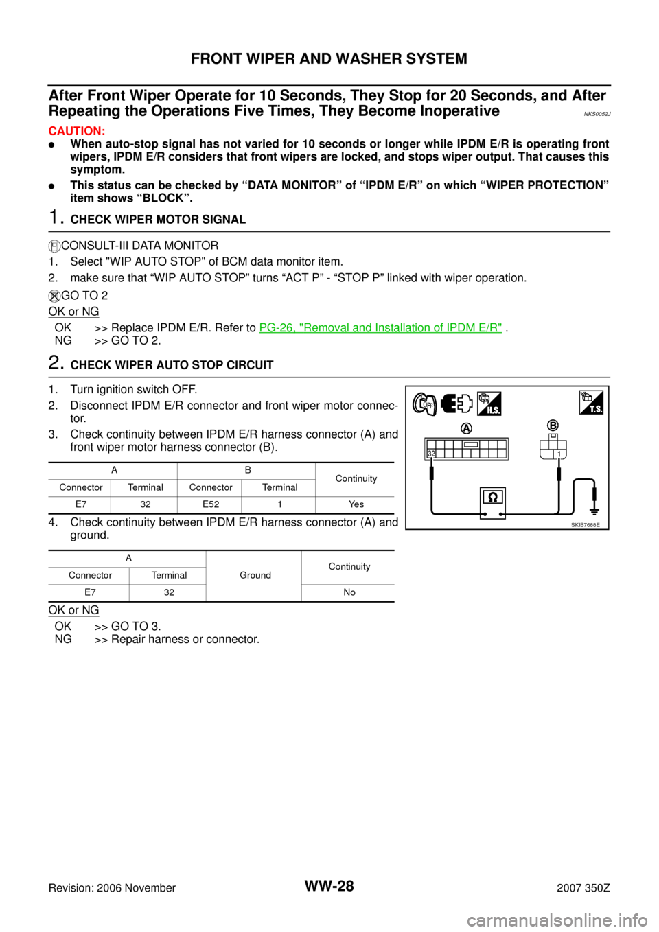
2. CHECK WIPER AUTO STOP CIRCUIT
1. Turn ignition switch OFF.
2. Disconnect IPDM E/R connector and front wiper motor connec-
tor.
3. Check continuity between IPDM E/R harness connector (A) and
front wiper motor harness connector (B).
4. Check continuity between IPDM E/R harness connector (A) and
ground.
OK or NG
OK >> GO TO 3.
NG >> Repair harness or connector.
AB
Continuity
Connector Terminal Connector Terminal
E7 32 E52 1 Yes
A
Ground Continuity
Connector Terminal
E7 32 No
SKIB7688E
Page 36 of 54

WW-36
REAR WIPER AND WASHER SYSTEM
Revision: 2006 November2007 350Z
REAR WIPER AND WASHER SYSTEMPFP:28710
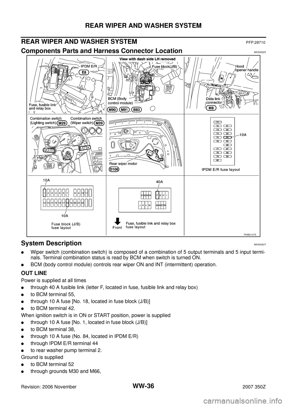
Components Parts and Harness Connector LocationNKS0052X
System DescriptionNKS0052Y
�Wiper switch (combination switch) is composed of a combination of 5 output terminals and 5 input termi-
nals. Terminal combination status is read by BCM when switch is turned ON.
�BCM (body control module) controls rear wiper ON and INT (intermittent) operation.
OUT LINE
Power is supplied at all times
�through 40 A fusible link (letter F, located in fuse, fusible link and relay box)
�to BCM terminal 55,
�through 10 A fuse [No. 18, located in fuse block (J/B)]
�to BCM terminal 42.
When ignition switch is in ON or START position, power is supplied
�through 10 A fuse [No. 1, located in fuse block (J/B)]
�to BCM terminal 38,
�through 10 A fuse (No. 84, located in IPDM E/R)
�through IPDM E/R terminal 44
�to rear washer pump terminal 2.
Ground is supplied
�to BCM terminal 52
�through grounds M30 and M66,
PKIB2147E