TROUBLE DIAGNOSIS
SRS-25
C
D
E
F
G
I
J
K
L
MA
B
SRS
Revision: 2006 November2007 350Z
CONSULT-lll FunctionNHS0000M
DIAGNOSIS MODE FOR CONSULT-LLL
�“SELF-DIAG [CURRENT]”
A current self-diagnostic results (also indicated by the number of warning lamp flashes in the Diagnosis
mode) is displayed on the CONSULT-lll screen in real time. This refers to a malfunctioning part requiring
repairs.
�“SELF-DIAG [PAST]”
Self-diagnostic results previously stored in the memory are displayed on the CONSULT-lll screen. The
stored results are not erased until memory erasing is performed.
�“TROUBLE DIAG RECORD”
With TROUBLE DIAG RECORD, diagnostic results previously erased by a reset operation can be dis-
played on the CONSULT-lll screen.
�“ECU DISCRIMINATED NO.”
The diagnosis sensor unit for each vehicle model is assigned with its own, individual classification num-
ber. This number will be displayed on the CONSULT-lll screen, as shown. When replacing the diagnosis
sensor unit, refer to the part number for the compatibility. After installation, replacement with a correct unit
can be checked by confirming this classification number on the CONSULT-lll screen.
After repair, make sure the discriminated number of diagnosis sensor unit installed to vehicle are same.
Refer to SRS-51, "
ECU DISCRIMINATED NO." .
HOW TO CHANGE SELF-DIAGNOSIS MODE WITH CONSULT-LII
From User Mode to Diagnosis Mode
After selecting “AIR BAG” on the “SELECT SYSTEM” screen, User mode automatically changes to Diagnosis
mode.
From Diagnosis Mode to User Mode
To return to User mode from Diagnosis mode, touch “BACK” key of CONSULT-lll until “SELECT SYSTEM”
appears, then diagnosis mode automatically changes to User mode.
SPIRAL CABLE
SRS-43
C
D
E
F
G
I
J
K
L
MA
B
SRS
Revision: 2006 November2007 350Z
INSTALLATION
Install in the reverse order of removal.
CAUTION:
�The spiral cable may snap by steering operation if the cable
is installed in an improper position.
�The neutral position is set as follows.
Turn quietly the spiral cable clockwise to the end position.
Then turn it counterclockwise (about 2 and harf turns) and
stop turning at the point on which the stopper insertion
holes are in the same position.
The service part is installed in the neutral position by the
stopper and can be set without adjusting after the stopper
is removed.
�Do not turn the spiral cable rashly and also beyond the limit
number of turns. (These will cause cable snap.)
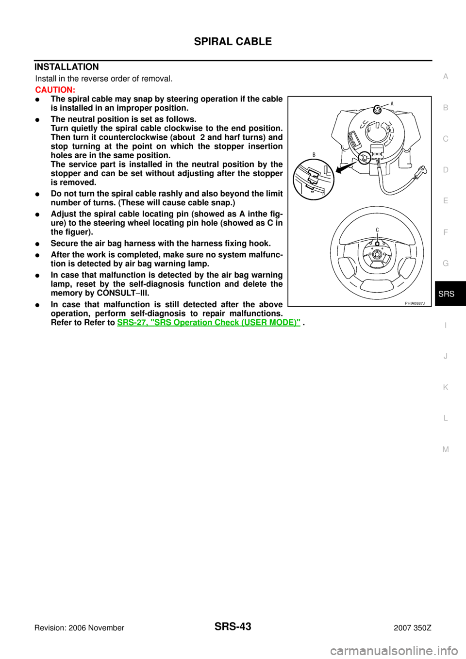
�Adjust the spiral cable locating pin (showed as A inthe fig-
ure) to the steering wheel locating pin hole (showed as C in
the figuer).
�Secure the air bag harness with the harness fixing hook.
�After the work is completed, make sure no system malfunc-
tion is detected by air bag warning lamp.
�In case that malfunction is detected by the air bag warning
lamp, reset by the self-diagnosis function and delete the
memory by CONSULT−IlI.
�In case that malfunction is still detected after the above
operation, perform self-diagnosis to repair malfunctions.
Refer to Refer to SRS-27, "
SRS Operation Check (USER MODE)" .
PHIA0887J