REAR SUSPENSION MEMBER
RSU-17
C
D
F
G
H
I
J
K
L
MA
B
RSU
Revision: 2006 November2007 350Z
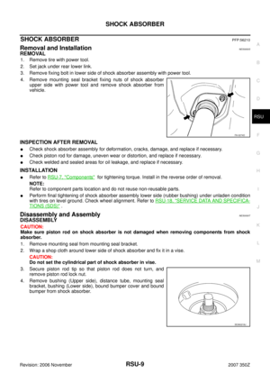
REAR SUSPENSION MEMBERPFP:55501
Removal and InstallationNES0000Z
REMOVAL
1. Remove tire with power tool.
2. Remove brake caliper with power tool. Hang it in a place where it will not interfere with work. Refer to BR-
39, "REAR DISC BRAKE" .
NOTE:
Avoid depressing brake pedal while brake caliper is removed.
3. Remove rear exhaust tube. Refer to EX-3, "
EXHAUST SYSTEM" .
4. Remove stabilizer bar. Refer to RSU-16, "
STABILIZER BAR" .
5. Remove drive shaft. Refer toRAX-10, "
REAR DRIVE SHAFT" .
6. Remove final drive. Refer to RFD-17, "
REAR FINAL DRIVE ASSEMBLY" .
7. Separate the attachment between parking brake cable and vehicle and rear suspension member. Refer to
PB-4, "
PARKING BRAKE CONTROL" .
8. Remove rear lower link and coil spring. Refer to RSU-15, "
REAR LOWER LINK & COIL SPRING" .
9. Remove fixing bolt in lower side of shock absorber.
10. Set jack under rear suspension member.
11. Remove fixing bolts and nuts tunnel stay and member stay from vehicle.
12. Remove fixing bolts and nuts of rear pin stay and then remove rear pin stay from vehicle.
13. Slowly lowering jack, then remove rear suspension member, suspension arm, radius rod, front lower link
and axle from vehicle as a unit.
14. Remove fixing bolts and nuts, then remove suspension arm, front lower link, radius rod from rear suspen-
sion member.
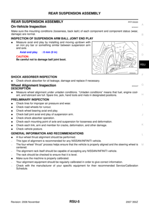
INSPECTION AFTER REMOVAL
�Check rear suspension member for deformation, cracks, and other damage and replace if necessary.
INSTALLATION
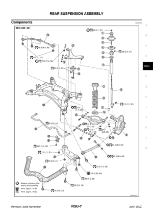
�Refer to RSU-7, "Components" , for tightening torque. Install in the reverse order of removal.
NOTE:
Refer to component parts location and do not reuse non-reusable parts.
�Perform final tightening of installation position of links (rubber bushing) under unladen condition with tires
on level ground. Check wheel alignment. Refer to RSU-18, "
SERVICE DATA AND SPECIFICATIONS
(SDS)" .
RSU-18
SERVICE DATA AND SPECIFICATIONS (SDS)
Revision: 2006 November2007 350Z
SERVICE DATA AND SPECIFICATIONS (SDS)PFP:00030
Wheel Alignment (Unladen*)NES00010
*: Fuel, engine coolant and lubricant are full. Spare tire, jack, hand tools and mats are in designated positions.
Ball JointNES00011
Wheelarch Height (Unladen*)NES00012
*: Fuel, engine coolant and lubricant are full. Spare tire, jack, hand tools and mats are in designated positions.Camber
Degree minute (Decimal degree)Minimum –2° 05′ (–2.08°)
Nominal –1° 35′ (–1.58°)
Maximum –1° 05′ (–1.08°)
Total toe-inDistanceMinimum 1.1 mm (0.043 in)
Nominal 1.9 mm (0.075 in)
Maximum 2.7 mm (0.106 in)
Angle (left wheel or right wheel)
Degree minute (Decimal degree)Minimum 0° 02′ 54″ (0.05°)
Nominal 0° 04′ 54″ (0.08°)
Maximum 0° 06′ 54″ (0.12°)
Axial end play0 mm (0 in)
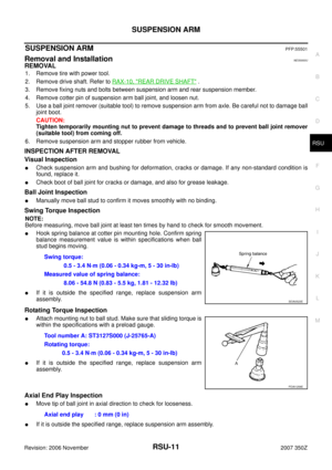
Swing torque 0.5 - 3.4 N·m (0.06 - 0.34 kg-m, 5 - 30 in-lb)
Measurement on spring balance (cotter pinhole position) 8.06 - 54.8 N (0.83 - 5.5 kg, 1.81 - 12.32 lb)
Rotating torque 0.5 - 3.4 N·m (0.06 - 0.34 kg-m, 5 - 30 in-lb)
Applied model225/45R18 (Front)
245/45R18 (Rear)245/40R18 (Front)
265/35R19 (Rear)
Coupe Roadster Coupe
Front (Hf) 683 mm (26.89 in) 683 mm (26.89 in)
Rear (Hr) 706 mm (27.80 in) 705 mm (27.76 in) 703 mm (27.68 in)
SFA818A


Revision: 2006 November2007 350Z
SERVICE DATA AND SPECIFICATIONS (SDS)PFP:00030
Wheel Alignment (Unladen*)NES00010
*: Fuel, engine coolant and lubricant ar")